AddEnergie SmartDC-V2 User manual
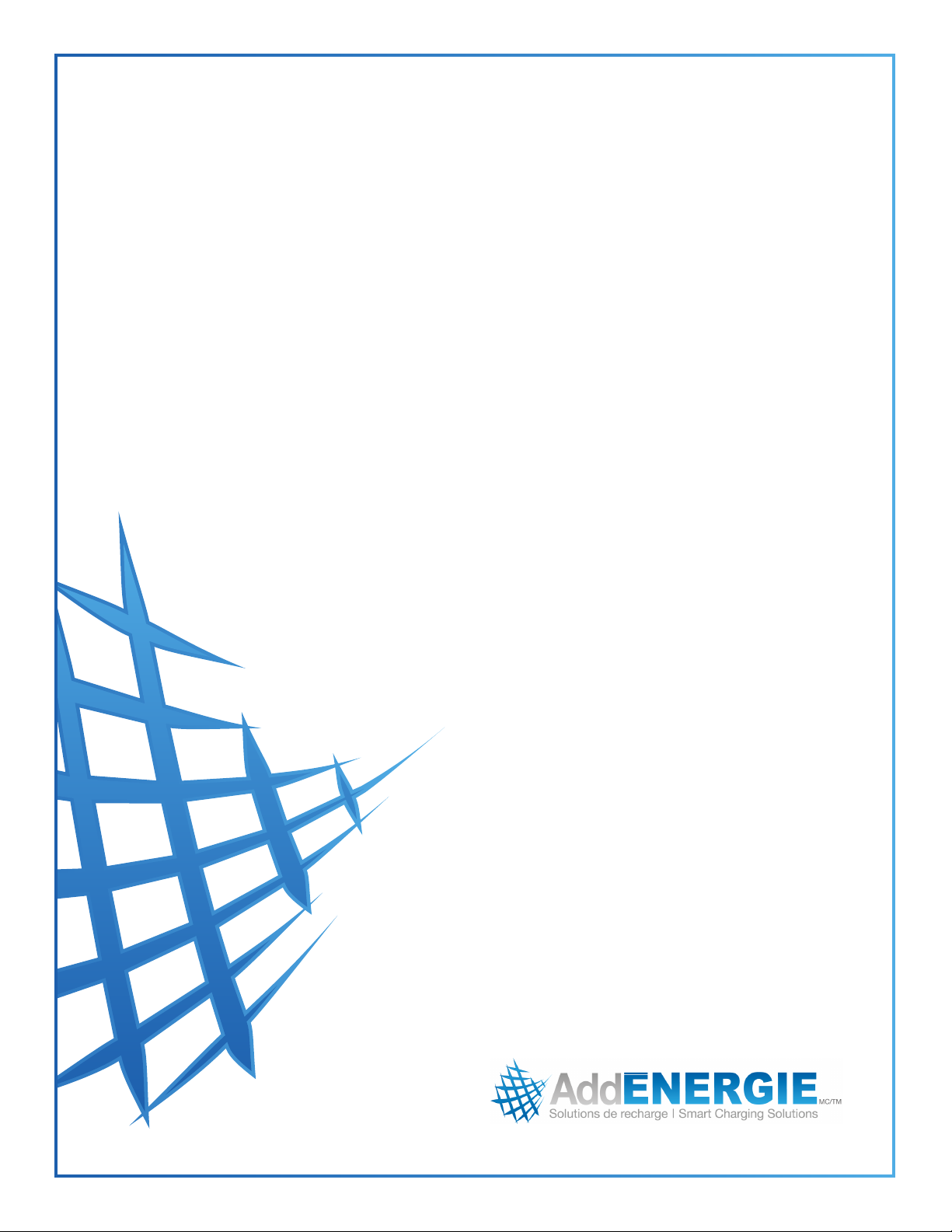
SmartDC-V2
Guide d’installation
Installation guide

2
© 2019 ADDÉNERGIE TECHNOLOGIES INC. TOUS DROITS RÉSERVÉS Les informations et les spécications contenues dans ce document sont sujettes aux changements, modications et ajouts à n’importe quel moment et sans préavis.
© 2019 ADDÉNERGIE TECHNOLOGIES INC. ALL RIGHTS RESERVED Information and specications contained in this document are subject to change, amendments and additions at any time, without notice.
ADD.IG.SMARTDC.FR.01.2019.v9

3
© 2019 ADDÉNERGIE TECHNOLOGIES INC. TOUS DROITS RÉSERVÉS Les informations et les spécications contenues dans ce document sont sujettes aux changements, modications et ajouts à n’importe quel moment et sans préavis.
© 2019 ADDÉNERGIE TECHNOLOGIES INC. ALL RIGHTS RESERVED Information and specications contained in this document are subject to change, amendments and additions at any time, without notice.
ADD.IG.SMARTDC.FR.01.2019.v9
Table des matières
Sécurité.......................................3
Dimensions ....................................4
Aperçu extérieur de la borne .......................5
Aperçu intérieur de la borne .......................6
Installation typique...............................7
Préparation du site ..............................8
Installation du socle sur la dalle de béton..............9
Installation de la borne sur le socle .................10
Installation du contrepoids........................11
Installation de l'affiche ...........................12
Branchement de la borne ........................13
Mise en route de la borne ........................14
Entretien et maintenance de la borne ...............15
Table of contents
Security .......................................3
Dimensions ....................................4
Exterior view of the station.........................5
Interior view of the station .........................6
Typical installation ...............................7
Site preparation.................................8
Installing the base onto a concrete floor slab ...........9
Installing the station onto the base..................10
Installing the counterweight .......................11
Installing the top sign............................12
Electrical connections to the station.................13
Station start-up ................................14
Care and maintenance of the station ................15

4
© 2019 ADDÉNERGIE TECHNOLOGIES INC. TOUS DROITS RÉSERVÉS Les informations et les spécications contenues dans ce document sont sujettes aux changements, modications et ajouts à n’importe quel moment et sans préavis.
© 2019 ADDÉNERGIE TECHNOLOGIES INC. ALL RIGHTS RESERVED Information and specications contained in this document are subject to change, amendments and additions at any time, without notice.
ADD.IG.SMARTDC.FR.01.2019.v9
Sécurité / Safety
IMPORTANTES INSTRUCTIONS DE SÉCURITÉ - CONSERVER CES INSTRUCTIONS
Veuillez lire ce guide attentivement avant d’entreprendre l’installation de la borne de recharge.
1. Cette borne de recharge a été conçue pour une fixation au sol, sur une surface non combustible.
2. Assurez-vous, auprès des autorités locales, que l’espace où vous installerez la borne ne comporte aucune canalisation, installation électrique
souterraine ou installation électrique auquel cas vous risqueriez de vous infliger de graves blessures.
3. Raccordez l’alimentation électrique de la borne de recharge avec des conducteurs de cuivre ou d’aluminium de calibre conforme à
la réglementation locale pour un circuit triphasé alimentant une charge de 54 kVA @ 480Y/277 V et conçu pour une utilisation à une
température maximale d'au moins 75 °C / 167 °F.
4. Mise à la terre : pour rendre sécuritaire l’usage de la borne de recharge AddÉnergie, celle-ci doit être raccordée à un circuit de mise à la terre
conforme à la réglementation locale, et installée par un électricien agréé.
5. Consultez un entrepreneur agréé, un électricien agréé ou un installateur formé pour assurer la conformité au code électrique local, à la
réglementation locale, aux normes de sécurité et aux conditions climatiques.
6. Toute modification d’une pièce de la borne de recharge annulera la garantie.
7. Comme les pièces peuvent présenter des arêtes vives, manipulez-les avec attention. Utilisez des lunettes et des gants de sécurité lors du
déballage et au cours de l’installation.
8. Certaines pièces sont lourdes et pourraient causer des blessures. Utilisez des techniques de levage adéquates et portez des chaussures de
sécurité en tout temps durant l’installation.
9. Ne mettez jamais les doigts dans la connexion du véhicule électrique.
10. N’utilisez jamais la borne de recharge si l’un des fils d’alimentation flexibles montre des signes de dommages ou si l’isolation est brisée.
11. N’utilisez jamais la borne de recharge si le boîtier principal est brisé, craqué, ouvert ou endommagé.
12. Cette borne de recharge a été conçue pour une utilisation avec véhicules électriques munis d’un connecteur CHAdeMO ou SAE J1772 Combo.
13. Cette borne de recharge doit être utilisée pour la recharge de véhicules ne demandant pas un environnement ventilé lors de la recharge.
14. Le remplacement d’un des composants de la borne de recharge doit être effectué par du personnel de service qualifié.
15. N’installez pas la borne de recharge sur des surfaces combustibles ou par-dessus celles-ci.
IMPORTANT SAFETY INSTRUCTIONS - PLEASE DO NOT DISCARD THESE INSTRUCTIONS
Carefully read this guide before installing the EVSE.
1. This station was designed to be ground-based and installed on a non-combustible surface.
2. Check with local authorities that the location where the EVSE is to be installed is free of underground pipelines or electrical equipment,
otherwise you could cause serious injury to yourself..
3. Connect the power station's supply with copper or aluminum conductors sized in conformity with the local code for a three-phase,
480Y/277 V, 54kVA circuit, rated for usage at a maximum temperature of at least 75°C / 167°F.
4. Grounding : to ensure the safe operation of the station, it must be connected to a grounding circuit compliant with local regulations and
installed by a certified electrician.
5. Communicate with a certified contractor, certified electrician or trained installer to ensure compliance with local building code, regulation,
security standards and weather conditions..
6. Any alteration of a part of the station will automatically void the warranty.
7. Handle parts with care, since they can be sharp-edged. Always use safety glasses and gloves when unpacking and installing.
8. Some parts are heavy and could cause injury. Use proper lifting techniques and wear safety boots at all times during the installation.
9. Never insert your fingers into the electric vehicle’s connector.
10. Never use the station if the flexible power cords seem damaged, or if the insulation is damaged.
11. Never use the station if the main case is broken, cracked, open, or damaged.
12. This station was designed to be used with electric vehicles equipped with a CHAdeMO or SAE J1772 Combo port.
13. This station is to be used to charge vehicles that do not require a ventilated environment during charging.
14. Replacement of the station’s parts must be performed by qualified service personnel.
15. Do not install the station on or over combustible surfaces.
5
© 2019 ADDÉNERGIE TECHNOLOGIES INC. TOUS DROITS RÉSERVÉS Les informations et les spécications contenues dans ce document sont sujettes aux changements, modications et ajouts à n’importe quel moment et sans préavis.
© 2019 ADDÉNERGIE TECHNOLOGIES INC. ALL RIGHTS RESERVED Information and specications contained in this document are subject to change, amendments and additions at any time, without notice.
ADD.IG.SMARTDC.FR.01.2019.v9
Spécifications / Specifications
Spécifications:
Type de borne de recharge: Borne de recharge rapide à courant continu
Connecteur de sortie: Conforme à la norme CHAdeMO et à la norme SAE J1772 Combo
Connecteur d'entrée: Bloc de distribution à vis, 350 MCM max. (pour les phases), 3/0 max. (pour le neutre)
Alimentation nominale: 480Y/277V triphasée (dois être protégée par disjoncteur ou fusible triphasé de 100 A)
Consommation maximale: 54 kVA @ 480 Vac triphasée
Puissance de sortie maximum: 50 kW@ 400 Vdc
Efficacité: 93% (ou mieux) @ 50 kW de sortie
Facteur de puissance: 0.98 ou mieux
La borne de recharge est une charge non linéaire. L'utilisation d'un transformateur ayant un facteur K d'au moins 9 est recommandé.
Protection intégrée:
• Contre les surtensions
• Les fuites de courant vers la terre
• Les défaillances d’isolation électrique entre l’entrée AC et la sortie DC
Plage de température d’opération: -40°C à +50°C
Étanchéité: Conforme à la norme NEMA 3R, pour utilisation extérieure
Poids à la livraison: 250 kg approximativement
Conformité aux normes de sécurité:
• UL 2002 : Système de recharge pour véhicules électriques
• CSA 22.2 No. 107.1-01: Alimentations électriques générales
• TIL I-44 : requis de certification intérimaire pour bornes de recharge pour véhicules électriques de moins de 600 Volts.
Specifications:
Type of charging station: Direct-current fast charging station
Output connector: Conforms to the CHAdeMO and SAE J1772 Combo standards
Input connector: Screw type distribution bloc, 350 MCM max. (for the phases), 3/0 max. (for the neutral)
Nominal voltage supply: Three-phase 480Y/277V (must be protected by a 100A, three-phase over- current protection device.)
Maximum power consumption: 54 kVA @ three-phase 480 VAC
Maximum output power: 50 kW @ 400 VDC
Efficiency: 93% (or better) @ 50 kW output
Power Factor: 0.98 or better
The charging station is a non linear load. The use of a transformer having a K-factor of at least 9 is recommended.
Integrated Protection:
• Against voltage surges
• Electric current leakages to ground
• Isolation failures between the AC input and DC output
Operating Temperature: -40°C to +50°C
Casing: Conforms to the NEMA 3R standards for exterior use
Security standards compliance:
• UL 2002: Charging system for electric vehicles
• CSA 22.2 No. 107.1-01: general power supply
• TIL I-44: Requires interim certification for charging stations designed for electric vehicles of less than 600 Volts
Modèle / Model: SmartDC
Info Compagnie / Company Info: AddÉnergie Technologies Inc
Révision du document / Document revision number: ADD.IG.SMARTDC.CA.01.2019.v9
©2019 AddÉnergie Technologies Inc. Tous droits réservés. Ce matériel est protégé par les lois sur les droits
d’auteur de plusieurs pays et ne devrait pas être modifié, reproduit ou distribué sans le consentement écrit
préalable de AddÉnergie Technologies.
©2019 AddÉnergie Technologies Inc. All rights reserved. Such material is protected by copyright laws of multiple
countries, and may not be modified, reproduced, or distributed without the prior written consent of AddÉnergie
Technologies.
* Illustré avec un Système de rappel des câbles (optionnel) / Shown with optional cable management system installed.

6
© 2019 ADDÉNERGIE TECHNOLOGIES INC. TOUS DROITS RÉSERVÉS Les informations et les spécications contenues dans ce document sont sujettes aux changements, modications et ajouts à n’importe quel moment et sans préavis.
© 2019 ADDÉNERGIE TECHNOLOGIES INC. ALL RIGHTS RESERVED Information and specications contained in this document are subject to change, amendments and additions at any time, without notice.
ADD.IG.SMARTDC.FR.01.2019.v9
Dimensions / Dimensions
660
1333
mm
mm
mm
mm
mm
mm
mm
mm
mm
mm
mm
mm
mm
mm
. ’’
. ’’
. ’’
. ’’
. ’’
. ’’
. ’’
. ’’
. ’’
. ’’
. ’’
. ’’
. ’’
. ’’
* Illustré avec un Système de rappel des câbles (optionnel)
Shown with optional cable management system installed
7
© 2019 ADDÉNERGIE TECHNOLOGIES INC. TOUS DROITS RÉSERVÉS Les informations et les spécications contenues dans ce document sont sujettes aux changements, modications et ajouts à n’importe quel moment et sans préavis.
© 2019 ADDÉNERGIE TECHNOLOGIES INC. ALL RIGHTS RESERVED Information and specications contained in this document are subject to change, amendments and additions at any time, without notice.
ADD.IG.SMARTDC.FR.01.2019.v9
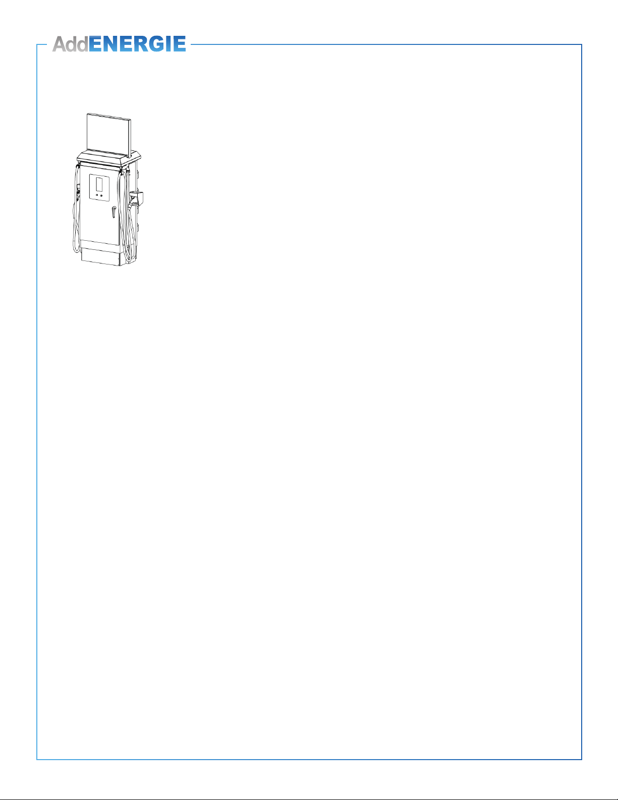
Aperçu extérieur de la borne
Exterior preview of the station
A
B
D
E
F
C
G
J
I
H
K
A : Locking door handle
B : Start button
C : Stop button
D : Display
E : RFID card reader
F : SAE J1772 Combo connector
G : CHAdeMO connector
H : Base
I : Air intake
J : Air outtake
K : Cable management system
A : Poignée de porte avec verrou
B : Bouton de démarrage
C : Bouton d’arrêt
D : Affichage
E : Lecteur de carte RFID
F : Connecteur SAE J1772 Combo
G : Connecteur CHAdeMO
H : Base
I : Entrée d’air
J : Sortie d’air
K : Système de rappel des câbles
8
© 2019 ADDÉNERGIE TECHNOLOGIES INC. TOUS DROITS RÉSERVÉS Les informations et les spécications contenues dans ce document sont sujettes aux changements, modications et ajouts à n’importe quel moment et sans préavis.
© 2019 ADDÉNERGIE TECHNOLOGIES INC. ALL RIGHTS RESERVED Information and specications contained in this document are subject to change, amendments and additions at any time, without notice.
ADD.IG.SMARTDC.FR.01.2019.v9
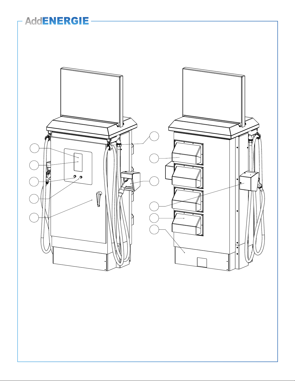
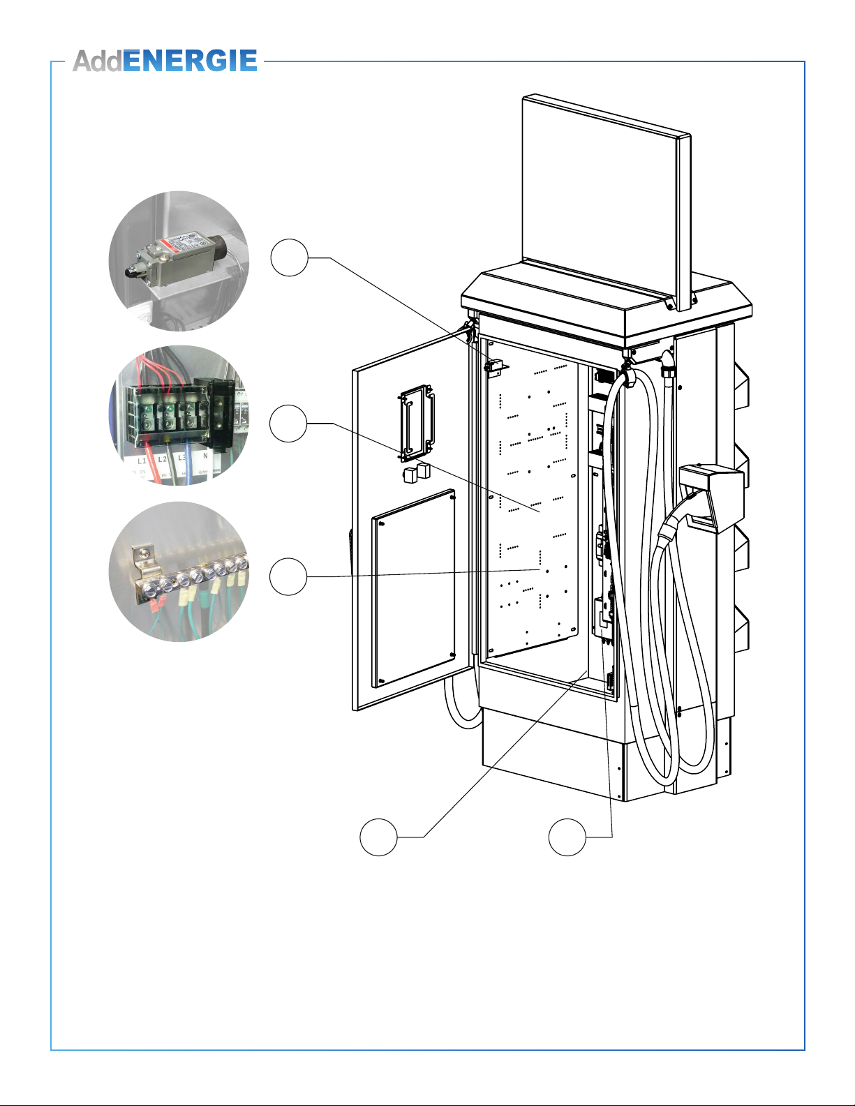
Aperçu intérieur de la borne
Interior preview of the station
A
D
E
B
C
A : Accès pour le câble d’alimentation
B : Bornier triphasé d’alimentation avec neutre
C : Interrupteur de porte
D : Modules de conversion AC/DC
E : Bornier de branchement de la mise à la terre
A : Power cable access
B : Three-phase and neutral terminals
C : Door switch
D : AC/DC conversion modules
E : Grounding terminal

9
© 2019 ADDÉNERGIE TECHNOLOGIES INC. TOUS DROITS RÉSERVÉS Les informations et les spécications contenues dans ce document sont sujettes aux changements, modications et ajouts à n’importe quel moment et sans préavis.
© 2019 ADDÉNERGIE TECHNOLOGIES INC. ALL RIGHTS RESERVED Information and specications contained in this document are subject to change, amendments and additions at any time, without notice.
ADD.IG.SMARTDC.FR.01.2019.v9
Installation typique / Typical installation
A : Cabinet de branchement au réseau, de mesurage et de distribution
B : Câble d’alimentation (3 phases 480Y/277 volts @ 100 A + NEUTRE + MALT)
C : Borne SmartDC
D : Sectionneur principal (doit être visible de la borne)
E : Espace de stationnement pour véhicule électrique
F : Bollard de protection
G : Dalle de béton
ATTENTION : Lorsqu’un transformateur abaisseur ou éleveur est nécessaire pour adapter la tension d’alimentation
disponible à la tension nominale de 480 Volts requise par la borne, l’utilisation d’un auto-transformateur Y, d’un
transformateurs Δ/Y, ou d’un transformateur Y/Y est acceptable. L’utilisation d’ auto-transformateur «Open Delta» ou de
transformateur dont le primaire est de type «Open Delta» est proscrite.
A : Electrical equipment cabinet (metering, protection and distribution)
B : Power cable (three-phase 480Y/277 Volts @ 100 A + NEUTRAL + GROUND)
C : SmartDC Station
D : Master disconnect switch (must be visible from the station)
E : Parking space for the electric vehicle
F : Protective bollard
G : Concrete Slab
WARNING: When a step down or a step up transformer is necessary to convert the available voltage to the required 480
Volts nominal, a Y auto transformer, a Δ/Y transformer, or a Y/Y transformer is suitable. Open Delta Type autotransformer and
transformers having their primary configured as «Open Delta» are proscribed.
DA B E C F G

10
© 2019 ADDÉNERGIE TECHNOLOGIES INC. TOUS DROITS RÉSERVÉS Les informations et les spécications contenues dans ce document sont sujettes aux changements, modications et ajouts à n’importe quel moment et sans préavis.
© 2019 ADDÉNERGIE TECHNOLOGIES INC. ALL RIGHTS RESERVED Information and specications contained in this document are subject to change, amendments and additions at any time, without notice.
ADD.IG.SMARTDC.FR.01.2019.v9
Préparation du site / Site preparation
1. La borne doit être installée sur une dalle de béton.
2. La surface de la dalle de béton doit être suffisante pour installer la borne et le bollards de protection, tout en laissant assez d’espace pour ouvrir la
porte et permettre aux utilisateurs de circuler. À titre indicatif, la figure ci-dessus procure les dimensions et distances minimales à respecter.
3. Le sol sous la dalle doit être bien drainé, et stabilisé (si requis) pour que son niveau ne soit pas affecté par le gel.
4. Un conduit électrique de diamètre approprié (selon le calibre des conducteurs électriques) doit permettre d’amener le câble électrique sous
le périmètre de la borne, préférablement dans la zone avant gauche.
REMARQUE : Le conduit de câblage doit être scellé pour empêcher l'infiltration d'humidité
IMPORTANT : S’il y a un mur derrière la borne, un espacement minimal de 16 pouces, doit être respecté entre la borne et le mur.
1. The station must be installed on a concrete slab.
2. The surface of the concrete slab must be large enough to install both the station and the protective bollards, while still leaving enough space
for the door to open, as well as for users to circulate. The figure above shows the minimum dimensions and distances required.
3. The ground underneath the slab must be properly drained and stabilized (as required), so that it is not affected by freezing.
4. An electric conduit of appropriate diameter (based on the electric wire gauge) must bring the electric cable under the station’s perimeter,
preferably in the forward-left zone under the station’s perimeter.
NOTE: Wiring conduit must be sealed to prevent moisture ingress
IMPORTANT: A clearance of at least 16 inches must be maintained between the enclosure's back and a rear facing wall
or any vertical obstacle.
Zone optimale
de sortie du
conduit électrique
Optimal output
zone for the
electric conduit
Périmètre
de la borne
Station’s
perimeter
Dégagement
pour ouverture
de la porte
Door opening
Capuchon
Cap
Bollard en acier 5”/125mm
Steel bollard 5”/125mm
L’ancrage des bollards doit
être conforme aux exigences
et à la règlementation locales.
Bollard anchoring must
comply with your local
regulations and
requirements
Avant de construire et d’installer
une dalle de béton, assurez-vous
qu’elle est conforme aux
exigences, à la réglementation
et au code de la construction
locaux.
Before building and installing
a concrete slab, ensure it is in
compliance with your local
building code.
11
© 2019 ADDÉNERGIE TECHNOLOGIES INC. TOUS DROITS RÉSERVÉS Les informations et les spécications contenues dans ce document sont sujettes aux changements, modications et ajouts à n’importe quel moment et sans préavis.
© 2019 ADDÉNERGIE TECHNOLOGIES INC. ALL RIGHTS RESERVED Information and specications contained in this document are subject to change, amendments and additions at any time, without notice.
ADD.IG.SMARTDC.FR.01.2019.v9
‘’
‘’
‘’ ‘’
‘’
‘’
‘’
‘’
‘’
‘’
‘’
‘’
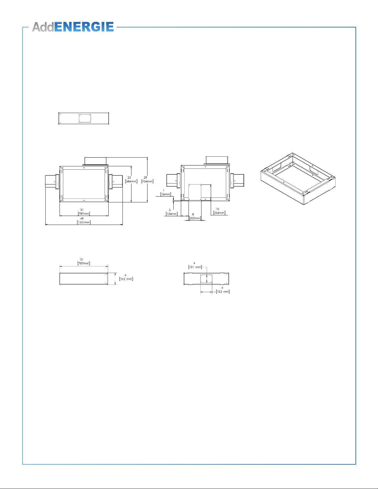
Installation du socle sur la dalle de béton
Base Installation on concrete slab
1. Il est recommandé d’utiliser des ancrages à béton 7.94 mm (5/16 in) en acier inoxydable de type « wedge anchors
(non fournis).
2. Percer la base de béton de trous de diamètres et de profondeur appropriés pour les ancrages, selon la position des trous
de fixation du socle tel qu’illustré.
3. Une fois les trous percés, placer le socle et visser les ancrages.
1. Use stainless steel 7.94 mm (5/16 in) concrete wedge anchors (not included).
2. Drill holes in the concrete slab of diameter and depth appropriate for the anchors, according to the base’s mounting holes,
as illustrated.
3. Once the holes are drilled, place the base and screw in the anchors.
Vue arrière
Rear view
Vue avant
Front view
Vue ISO
ISO view
Vue de haut
Top view
Vue de haut
Top view
Vue avant
Front view

12
© 2019 ADDÉNERGIE TECHNOLOGIES INC. TOUS DROITS RÉSERVÉS Les informations et les spécications contenues dans ce document sont sujettes aux changements, modications et ajouts à n’importe quel moment et sans préavis.
© 2019 ADDÉNERGIE TECHNOLOGIES INC. ALL RIGHTS RESERVED Information and specications contained in this document are subject to change, amendments and additions at any time, without notice.
ADD.IG.SMARTDC.FR.01.2019.v9
Installation de la borne sur le socle
Installing the station onto the base
1. Enlever la plaque d’accès pour permettre le passage du câble d’alimentation.
2. Déposer la borne sur son socle en prenant soin de faire passer le câble d’alimentation par le trou d’accès.
3. Percer la plaque d’accès, d’un diamètre approprié, pour le serre-fil.
4. Installer le serre-fil sur la plaque d’accès.
5. Introduire le câble d’alimentation dans le serre-fil.
6. Replacer la plaque d’accès au fond de la borne.
1. Remove the access plate to allow the passage of the power cable.
2. Place the station onto its base, making sure to pass the power cable through the access hole.
3. Punch a hole in the access plate of an appropriate diameter for the cable connector.
4. Install the cable connector onto the access plate.
5. Insert the power cable into the cable connector.
6. Put the access plate back in place.
Plaque d’accès pour l’alimentation
Power cable access plate

13
© 2019 ADDÉNERGIE TECHNOLOGIES INC. TOUS DROITS RÉSERVÉS Les informations et les spécications contenues dans ce document sont sujettes aux changements, modications et ajouts à n’importe quel moment et sans préavis.
© 2019 ADDÉNERGIE TECHNOLOGIES INC. ALL RIGHTS RESERVED Information and specications contained in this document are subject to change, amendments and additions at any time, without notice.
ADD.IG.SMARTDC.FR.01.2019.v9
1. Installer la plaque d'aluminium avec les butées d'arrêt de caoutchouc
et la fixer avec les boulons. Assurer-vous que la plaque d'aluminium
repose fermement sur le sol.
2. Retirer la vis de sécurité et relâcher le contrepoids.
ATTENTION : NE PAS mettre les mains ou les doigts entre
les butées d'arrêt de caoutchouc et le contrepoids.
3. Placer le couvercle sur le système de contrepoids.
1. Install the aluminum plate with the rubber stoppers and secure it with
the bolts. Ensure the aluminum plate is resting firmly on the ground.
2. Remove the security screw and release the counterweight.
CAUTION: DO NOT put your hands or fingers between
the rubber stoppers and the counterweight.
3. Place the cover over the counterweight system.
Installation du contrepoids
Installing the counterweight
1
2
3
IMPORTANT : NE PAS retirer les
butées d'arrêt de caoutchouc de la
plaque d'aluminium, cela pourrait
endommager la borne de recharge.
IMPORTANT: DO NOT remove the
rubber stoppers from the aluminum
plate, since this may result in
damage to the charging station.
14
© 2019 ADDÉNERGIE TECHNOLOGIES INC. TOUS DROITS RÉSERVÉS Les informations et les spécications contenues dans ce document sont sujettes aux changements, modications et ajouts à n’importe quel moment et sans préavis.
© 2019 ADDÉNERGIE TECHNOLOGIES INC. ALL RIGHTS RESERVED Information and specications contained in this document are subject to change, amendments and additions at any time, without notice.
ADD.IG.SMARTDC.FR.01.2019.v9
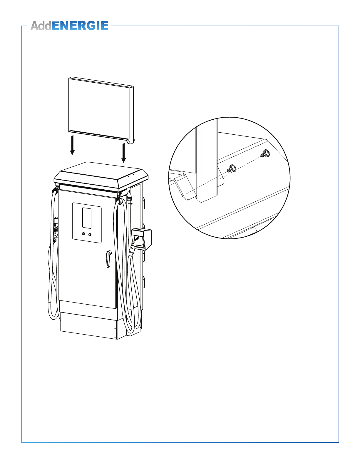
1. Aligner le panneau avec les 4 trous sur le dessus de la borne de recharge.
2. Visser les 4 boulons pour fixer le panneau.
REMARQUE : S’il y a des problèmes lors de l'installation de l’affiche, veuillez contacter le soutien technique
d’AddEnergie.
1. Align the panel with the 4 holes on top of the charging station.
2. Screw the 4 bolts to secure the panel.
NOTE: If there are any issues while installing the Top Sign, please contact AddEnergie support.
Installation de l'affiche
Installing the top sign
15
© 2019 ADDÉNERGIE TECHNOLOGIES INC. TOUS DROITS RÉSERVÉS Les informations et les spécications contenues dans ce document sont sujettes aux changements, modications et ajouts à n’importe quel moment et sans préavis.
© 2019 ADDÉNERGIE TECHNOLOGIES INC. ALL RIGHTS RESERVED Information and specications contained in this document are subject to change, amendments and additions at any time, without notice.
ADD.IG.SMARTDC.FR.01.2019.v9
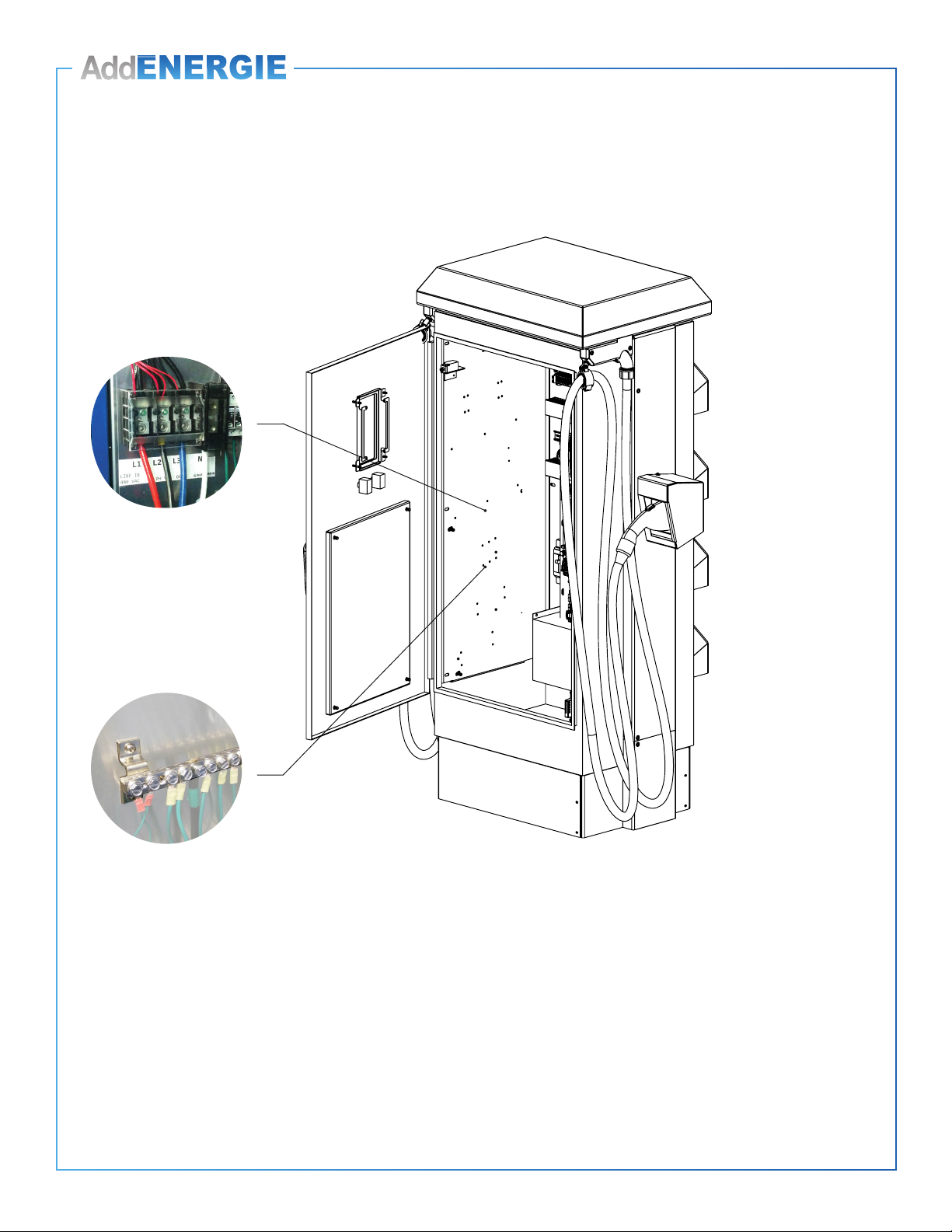
1. Brancher les 3 conducteurs sur le bornier triphasé d’alimentation.
2. Brancher le NEUTRE sur le bornier de neutre.
3. Brancher la MALT sur le bornier de la mise à la terre.
REMARQUE : Les connecteurs sont compatibles avec les fils de cuivre et d'aluminium.
1. Connect the three conductors into the three-phase power terminal.
2. Connect the NEUTRAL conductor into the neutral terminal.
3. Connect the GROUND into the grounding terminal.
NOTE: Connectors are compatible with copper and aluminum wire.
Branchement de la borne
Electrical connections to the station
A B C

16
© 2019 ADDÉNERGIE TECHNOLOGIES INC. TOUS DROITS RÉSERVÉS Les informations et les spécications contenues dans ce document sont sujettes aux changements, modications et ajouts à n’importe quel moment et sans préavis.
© 2019 ADDÉNERGIE TECHNOLOGIES INC. ALL RIGHTS RESERVED Information and specications contained in this document are subject to change, amendments and additions at any time, without notice.
ADD.IG.SMARTDC.FR.01.2019.v9
Mise en route de la borne
Station start-up
Avant de mettre la borne sous tension :
1. L’électricien doit s’assurer que l’installation électrique est conforme au code électrique en vigueur.
2. Les disjoncteurs à l’intérieur de la borne de recharge doivent être en position ‘ON’.
Lors de la mise sous tension :
1. L’électricien doit valider la tension de 480Y/277 V triphasée à la borne.
Après la mise sous tension :
1. Fermer et verrouiller la porte du boîtier de la borne de recharge.
Mise en service :
1. À la suite de la mise sous tension de la borne, des messages apparaîtront sur l’affichage à l’avant de la borne, confirmant
que celle-ci est maintenant fonctionnelle.
2. La borne de recharge essaie maintenant de communiquer avec le serveur d’AddÉnergie.
* Pour permettre cette communication, l’électricien doit s’assurer que la passerelle de communication est installée selon les
directives du guide et bien alimentée. (ref. Guide d’installation de la passerelle)
3. Lorsque la borne et la passerelle sont sous tension, veuillez communiquer avec le soutien technique d’AddÉnergie pour
compléter la configuration : (877) 505-2674 poste 201.
Before turning the station on :
1. The electrician must ensure that the electrical installation conforms to the applicable electrical code.
2. The circuit breakers inside the charging station must be in the “ON” position.
As the station is being turned on :
1. The electrician must verify that the station’s three-phase 480Y/277 V voltage is within specifications.
Once the station is on :
1. Close and lock the charging station’s casing door.
Putting the station into service :
1. After the station has been turned on, messages will appear on the screen in front of the station, confirming that it is now
functional.
2. The station will then attempt to communicate with the AddÉnergie servers. To allow this communication, the electrician must
ensure that the communication gateway is installed (based on the directions in the guide) and powered on.
(reference : Gateway Installation Guide).
3. Once the station and gateway are powered on, please communicate with the technical support of AddÉnergie to complete
the configuration : (877) 505-2674 ext. 203.

17
© 2019 ADDÉNERGIE TECHNOLOGIES INC. TOUS DROITS RÉSERVÉS Les informations et les spécications contenues dans ce document sont sujettes aux changements, modications et ajouts à n’importe quel moment et sans préavis.
© 2019 ADDÉNERGIE TECHNOLOGIES INC. ALL RIGHTS RESERVED Information and specications contained in this document are subject to change, amendments and additions at any time, without notice.
ADD.IG.SMARTDC.FR.01.2019.v9
Entretien et maintenance de la borne
Care and maintenance of the station
CETTE BORNE DE RECHARGE NÉCESSITE UN ENTRETIEN ANNUEL POUR QU’ON PUISSE S’ASSURER
DE SON BON FONCTIONNEMENT.
L’ENTRETIEN DOIT ÊTRE EFFECTUÉ PAR ADDÉNERGIE.
Voici en quoi consiste l’entretien :
1. Le nettoyage ou le remplacement des filtres du système de refroidissement.
* Il est important de maintenir un bon flux d’air à l’intérieur de la borne pour refroidir certaines composantes.
2. L’inspection des composants critiques de la borne.
* Ensembles câbles/connecteurs, modules de conversion de puissance, etc.
Il est recommandé d’augmenter la fréquence des entretiens de la borne de recharge à 4 fois par année
dans les contextes suivants :
• Quand la borne est installée dans un environnement poussiéreux.
• Quand l’usage cumulé moyen de la borne excède 1 heure de recharge par jour
THIS STATION REQUIRES YEARLY MAINTENANCE TO ENSURE PROPER OPERATION.
MAINTENANCE MUST BE PERFORMED BY ADDÉNERGIE.
It consists of :
1. Cleaning or replacing the cooling system filters.
*It is important to maintain proper airflow inside the station to adequately cool the power modules.
2. Inspecting the critical components of the station.
*cables/connectors, power modules, etc.
We recommend that you increase the frequency of station maintenance to 4 times a year in the
following situations :
• When the station is installed in a dusty area.
• When the station’s average cumulative use exceeds 1 hour of charging per day.

18
2019 ADDÉNERGIE TECHNOLOGIES INC. ALL RIGHTS RESERVED. Information and Specications Contained in this Document are Subject to Change, Amendments, and Additions at any Time, Without Notice

19
2019 ADDÉNERGIE TECHNOLOGIES INC. ALL RIGHTS RESERVED. Information and Specications Contained in this Document are Subject to Change, Amendments, and Additions at any Time, Without Notice

T. 1 877 505-2674
F. 855 505-2674
addenergie.ca
Pour toute question concernant l’installation ou la mise en route :
(877) 505-2674 poste 201
AddÉnergie Technologies inc.
Siège social : 2800 Louis-Lumière, Suite 100, Québec (QC) G1P 0A4 CANADA
Bureau de l’Ontario : 7420 Airport Road, Mississauga (ON) L4T 4E5 CANADA
Installation or commissioning questions:
(877) 505-2674 ext. 203
AddÉnergie Technologies Inc.
Head office: 2800 Louis-Lumière, Suite 100, Quebec (QC) G1P 0A4 CANADA
Ontario office: 7420 Airport Road, Mississauga (ON) L4T 4E5 CANADA
Pour nous joindre
Contact us
Table of contents
Other AddEnergie Batteries Charger manuals

AddEnergie
AddEnergie SmartTWO User manual

AddEnergie
AddEnergie CoRe+V2 User manual

AddEnergie
AddEnergie CoRe+ C+V1-PED-ADD User manual

AddEnergie
AddEnergie SmartDC User manual

AddEnergie
AddEnergie FLO SmartDC User manual

AddEnergie
AddEnergie SmartTWO User manual

AddEnergie
AddEnergie CoRe+ Instruction Manual
Popular Batteries Charger manuals by other brands


Duracell
Duracell DR7000LI user manual

KUBE SYSTEMS
KUBE SYSTEMS KS Clock user guide

Manson Engineering Industrial
Manson Engineering Industrial SBC-9138 user manual

Fisher-Price
Fisher-Price POWER WHEELS P6828 manual

Lenmar
Lenmar Mach 1+ SpeedCharger 3.6 Volt product manual

Kärcher
Kärcher Battery Power+ Fast Charger 18/60 manual