AddEnergie SmartTWO User manual

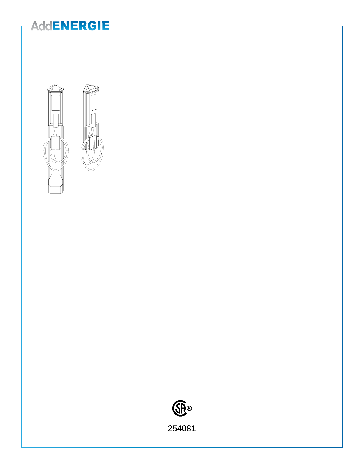
SmartTWOTM
Installation Guide
2
© 2019 ADDÉNERGIE TECHNOLOGIES INC. ALL RIGHTS RESERVED Information and specications contained in this document are subject to change, amendments and additions at any time, without notice
V20-2019-04-03
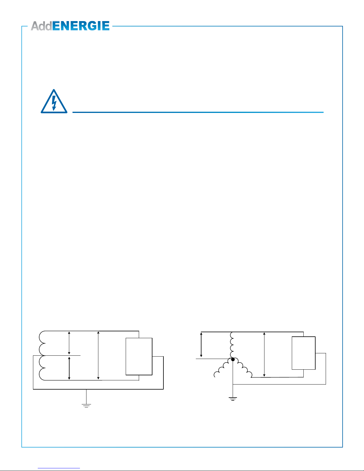
Split Phase 120/240 VAC Supply or 3 phase 120/208 VAC C (must be protected by a 40 A fuse or circuit breaker)
Both lines must have 120V between ground.
Voltage supply must be grounded.
Require 2 lines and 1 ground connection. Neutral is not used. (Refer to Figure 1 and Figure 2).
Maximum output power: 7.2kW @ 240 VAC or 6.3KW @ 208 VAC
Built-in protection against overvoltage conditions and leakage current to ground
Connect the power supply of the EVSE with caliber 2 to 8 copper or aluminium conductors
Any EVSE part alteration will automatically void the warranty.
Install the Communication Gateway prior to the Commissioning of the Station
The Communication Gateway is the property of AddÉnergie. Fees will be charged if the Gateway is damaged
or lost.
IMPORTANT ELEMENTS TO CONSIDER WHEN INSTALLING THE COMMUNICATION GATEWAY:
• An Outdoor installation is recommended. The Customer must provide a waterproof PVC box and install it less
than 50 meters (164ft.) from the stations.
• Never use a GFCI outlet to power the Communication Gateway.
Contact us when the Communication Gateway is installed to validate the signal levels and activate Commissioning
or for any other questions: 1-877- 505-2674
IMPORTANT
Fig. 1 Fig. 2
N eut ra l
(N.C)
120VAC
240VAC
L1
L2
Spl it P hase 120/240 VAC Supply
Charging
Station
120VAC
GND
GND
A
BC
208 VAC
120VAC
3 phase 120/208 VAC Supply
GND
Charging
Station
L1
L2
(N.C) N eut ra l
GND

3
© 2019 ADDÉNERGIE TECHNOLOGIES INC. ALL RIGHTS RESERVED Information and specications contained in this document are subject to change, amendments and additions at any time, without notice
V20-2019-04-03
Table of Contents
Specications ..................................4
Maintenance and Safety ..........................5
Congurations ..................................6
Pedestal ......................................7
Wall Mount ...................................12
Connection ...................................13
Front Panel and Base Cover Installation..............15
Station Heads Installation on the Bases..............17
Installation of the Panel on the Charging Head.........18
Preliminary Tests and Commissioning ...............19
4
© 2019 ADDÉNERGIE TECHNOLOGIES INC. ALL RIGHTS RESERVED Information and specications contained in this document are subject to change, amendments and additions at any time, without notice
V20-2019-04-03
Specications
Model: SmartTWOTM
Revision: V4
Company Info: AddEnergie Technologies Inc.
Document revision number: V20-2019-04-03
© 2019 AddÉnergie Technologies Inc. All Rights Reserved. AddÉnergie
Technologies Inc. reserves the right to alter product offerings and
specications at any time without notice and is not responsible for
typographical or graphical errors that may appear in this document. All
pictures shown are for illustration purposes only. Actual product may vary
due to product enhancements.
EVSE type: Level 2
Output connector: SAE J1172 compliant
Split Phase 120/240 VAC Supply or 3 phase 120/208 VAC (must be protected by a 40 A fuse or circuit breaker)
Maximum output power: 7.2kW @ 240 VAC or 6.3KW @ 208 VAC
Built-in protection against overvoltage conditions and leakage current to ground
Ingress Protection rating: Certied NEMA3R enclosure, suitable for outdoor use
Shipping weight: Approximately 30kg for the single pedestal conguration
Patent: US 9,421,878B2
Security standard compliance:
• CSA C22.2 No. 0-10 General Requirements – Canadian Electrical code, part II
• CSA 281.1-12/UL2231-1 Standard for safety for personnel protection systems for electrical vehicle
(EV) supply circuits: General requirements
• CSA 281.2-12/UL2231-2 Standard for safety for personnel protection systems for electric vehicle (EV)
supply circuits: Particular requirements for protection devices for use in charging systems
• CSA C22.2 No. 280-13/UL2594 (1st edition) Electric vehicle supply equipment (EVSE)

5
© 2019 ADDÉNERGIE TECHNOLOGIES INC. ALL RIGHTS RESERVED Information and specications contained in this document are subject to change, amendments and additions at any time, without notice
V20-2019-04-03
www
Maintenance and Safety
IMPORTANT SAFETY INSTRUCTIONS - PLEASE DO NOT DISCARD THESE INSTRUCTIONS
Carefully read this guide before installing the EVSE
1. This EVSE was designed to be ground-based, wall-mounted or pole-mounted.
1.1. For the pedestal version, it must be mounted on a non-combustible surface.
1.2. For the wall-mounted version, you must make sure the wall on which it will be mounted is
strong enough, and that you use the appropriate type of anchors.
1.3. For the pole mounted version, you must make sure the pole on which it will be mounted is
strong enough, and that you use the appropriate type of tether straps.
2. Make sure with local authorities that the location where the EVSE is to be installed is free from
underground pipelines or electrical equipment, otherwise you might inict yourself serious injuries.
3. Connect the power supply of the EVSE with caliber 2 to 8 copper or aluminium conductors rated for
usage at a temperature of at least 75°C.
4. Grounding: to ensure the safe operation of the AddÉnergie’s EVSE, it must be connected to a
grounding circuit compliant with local regulations and installed by a certied electrician.
5. Communicate with a certied contractor, certied electrician or trained installer to ensure compliance
with local building code, regulation, security standards and weather conditions.
6. Any EVSE part alteration will automatically void the warranty.
7. Handle parts with care, since they can be sharp-edged. Always use safety glasses and gloves when
unpacking and installing.
8. Some parts are heavy and could cause injuries. Use proper lifting techniques and wear safety boots
at all times during installation.
9. Never insert your nger into the electric vehicle connection.
10. Never use the EVSE if the exible power cord seems damaged or if insulation is damaged.
11. Never use the EVSE if the main case is broken, cracked, open or damaged.
12. This EVSE was designed to be used with electric vehicles equipped with a SAE-J1772 connector.
13. This EVSE is to be used to charge vehicles that do not require a ventilated environment during
charging.
14. Replacement of the EVSE’s head, gun module, gun cable, or gun must be performed by qualied
service personnel.
15. When the case of the EVSE’s head is open, all gaskets must be replaced.
16. Do not install on or over a combustible surface.
6
© 2019 ADDÉNERGIE TECHNOLOGIES INC. ALL RIGHTS RESERVED Information and specications contained in this document are subject to change, amendments and additions at any time, without notice
V20-2019-04-03
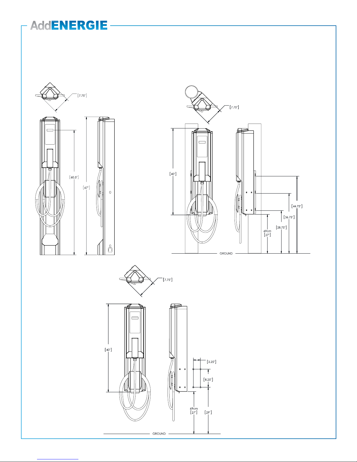
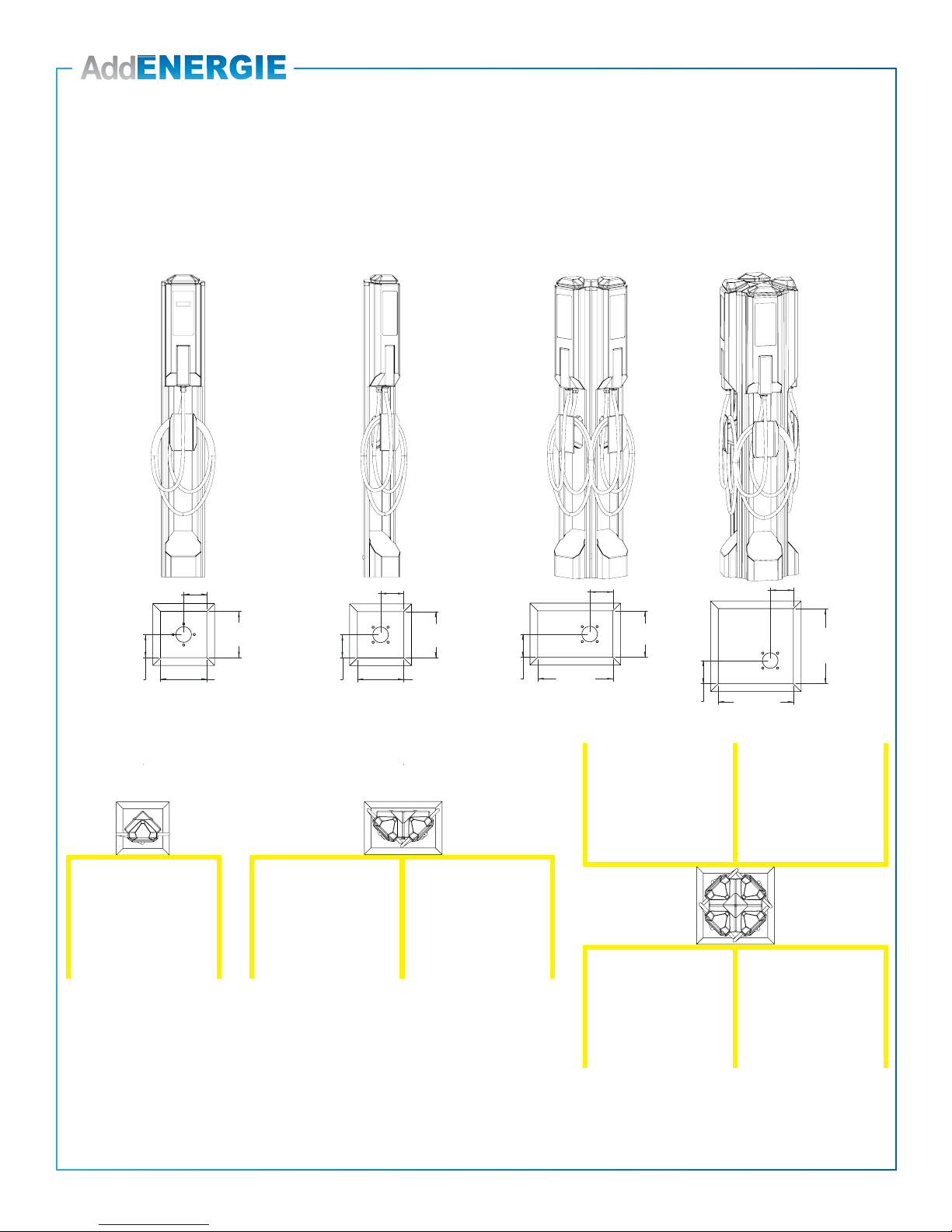
Congurations
Dimensions
154cm
20cm
170cm
102cm
73cm
93cm
114cm
20cm
102cm
8.3cm
21cm
74cm
20cm
Leave a minimum of 7,6 cm (3’’)
on top of the main structure to
insert the EVSE’s head.
Leave a minimum of 7,6 cm (3’’)
on top of the main structure
to insert the EVSE’s head.
Leave a minimum of 7,6 cm (3’’)
on top of the main structure
to insert the EVSE’s head.
Pole-mounted EVSE
Pedestal EVSE
Wall-mounted EVSE
Drilling pattern
© 2019 ADDÉNERGIE TECHNOLOGIES INC. ALL RIGHTS RESERVED Information and specications contained in this document are subject to change, amendments and additions at any time, without notice
V20-2019-04-03
7
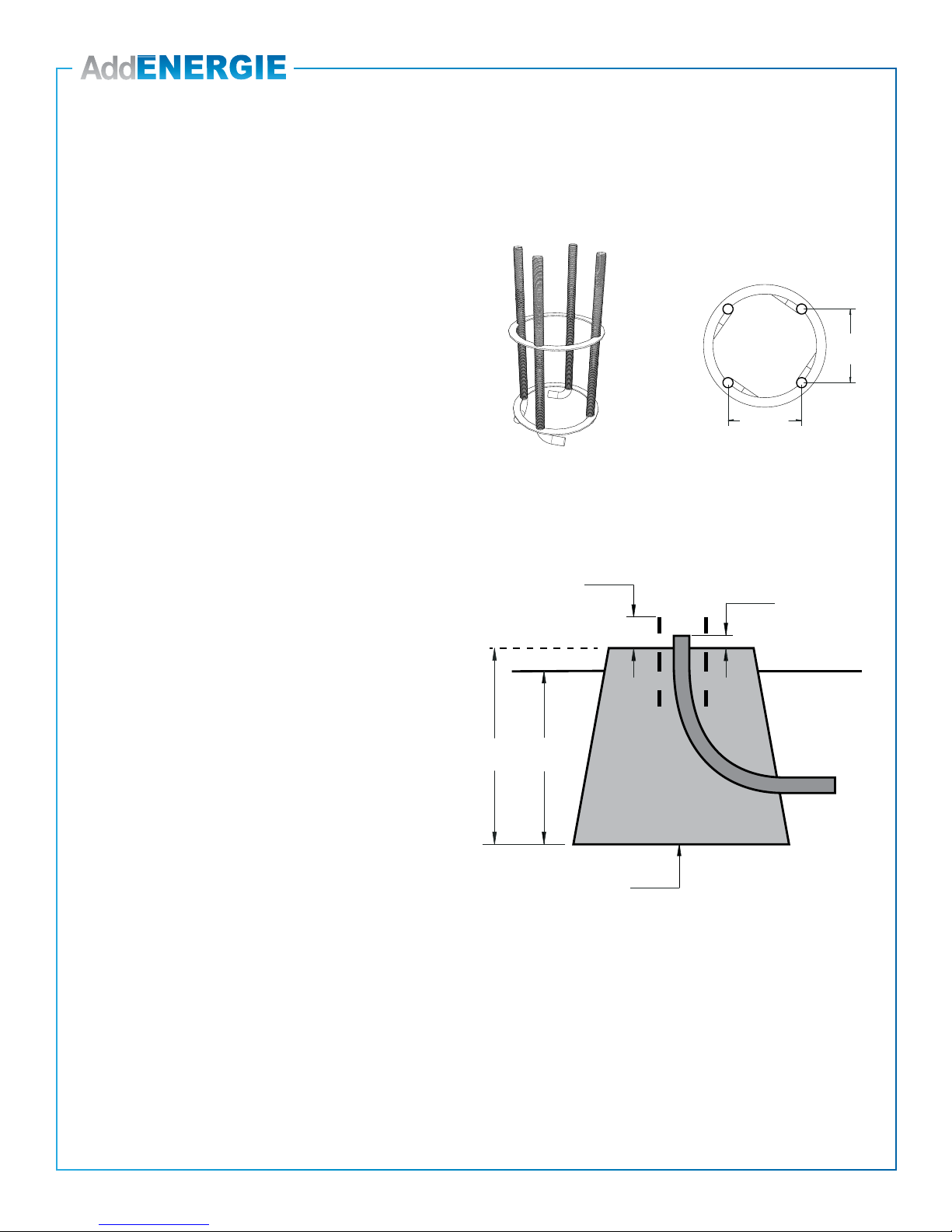
Pedestal
Site preparation
85.7 mm
(3.375’’)
85.7 mm
(3.375’’)
Fig. 1:Ancrage préfabriquée /
Prefabricated anchor
Fig. 2: Patron d’espacement
Threaded rod spacing
Fig. 3: Base de béton /
Concrete base
H / HP / D
S / A
9 cm
(3.5’’) 2.5 cm
(1’’)
ANCHOR
The installer can use a prefabricated anchor
offered by AddÉnergie (part number: S2-V2-
ACCSP-01-03) or make his own using 12”
long ½” threaded rods spaced according to the
pattern shown on left.
CONCRETE BASE
The base can be prefabricated or made on site
using concrete formwork.
Determine the base’s height (H), depth in the
ground (D) and the surface area (A) of its sole
according to the soil type and the freeze thaw
specications of the installation area.
Use an electrical conduit of the appropriate size
with a diameter of 2’’ or less to bring the electrical
cables to the center of the anchor.
The dimension of the top of the base, and the
position of the anchor shall be determined
according to the specic charging station
conguration, as detailed on the next page.
Fig: 1: Prefabricated anchor Fig: 2: Threaded rod spacing
HD
Fig. 3: Concrete base
8
© 2019 ADDÉNERGIE TECHNOLOGIES INC. ALL RIGHTS RESERVED Information and specications contained in this document are subject to change, amendments and additions at any time, without notice
V20-2019-04-03
Piédestal simple, face parallèle
Single pedestal, straight facing
Piédestal simple, face à angle
Single pedestal, angle facing
Piédestal double
Double pedestal
Piédestal quadruple
Quad pedestal
27 cm
(10.5’’) min.
13 cm (5.25’’)
43 cm
(17’’) min.
13 cm
(5.25’’)
43 cm
(17’’) min.
13 cm (5.25’’)
43 cm
(17’’) min.
13 cm
(5.25’’)
27 cm
(10.5’’) min.
13 cm (5.25’’)
13 cm
(5.25’’)
27 cm
(10.5’’) min.
27 cm
(10.5’’) min.
13 cm (5.25’’)
27 cm
(10.5’’) min.
13 cm
(5.25’’)
Pedestal
Anchor positioning
Piédestal simple, face parallèle
Single pedestal, straight facing
Piédestal simple, face à angle
Single pedestal, angle facing
Piédestal double
Double pedestal
Piédestal quadruple
Quad pedestal
27 cm
(10.5’’) min.
13 cm (5.25’’)
43 cm
(17’’) min.
13 cm
(5.25’’)
43 cm
(17’’) min.
13 cm (5.25’’)
43 cm
(17’’) min.
13 cm
(5.25’’)
27 cm
(10.5’’) min.
13 cm (5.25’’)
13 cm
(5.25’’)
27 cm
(10.5’’) min.
27 cm
(10.5’’) min.
13 cm (5.25’’)
27 cm
(10.5’’) min.
13 cm
(5.25’’)
The pedestal can
be installed in the
center of the parking
stall. In such case,
the anchor shall
be layed out on
the base as shown
above, to make sure
that the station is
straight facing.
Piédestal simple, face parallèle
Single pedestal, straight facing
Piédestal simple, face à angle
Single pedestal, angle facing
Piédestal double
Double pedestal
Piédestal quadruple
Quad pedestal
27 cm
(10.5’’) min.
13 cm (5.25’’)
43 cm
(17’’) min.
13 cm
(5.25’’)
43 cm
(17’’) min.
13 cm (5.25’’)
43 cm
(17’’) min.
13 cm
(5.25’’)
27 cm
(10.5’’) min.
13 cm (5.25’’)
13 cm
(5.25’’)
27 cm
(10.5’’) min.
27 cm
(10.5’’) min.
13 cm (5.25’’)
27 cm
(10.5’’) min.
13 cm
(5.25’’)
For an initial installation of a single pedestal
that will evolve to a dual in the future, it is
recommended to install the base at the
intersection of 2 parking stalls, with the
anchor positioned to have the charging
station face at 45°.
Piédestal simple, face parallèle
Single pedestal, straight facing
Piédestal simple, face à angle
Single pedestal, angle facing
Piédestal double
Double pedestal
Piédestal quadruple
Quad pedestal
27 cm
(10.5’’) min.
13 cm (5.25’’)
43 cm
(17’’) min.
13 cm
(5.25’’)
43 cm
(17’’) min.
13 cm (5.25’’)
43 cm
(17’’) min.
13 cm
(5.25’’)
27 cm
(10.5’’) min.
13 cm (5.25’’)
13 cm
(5.25’’)
27 cm
(10.5’’) min.
27 cm
(10.5’’) min.
13 cm (5.25’’)
27 cm
(10.5’’) min.
13 cm
(5.25’’)
A quad pedestal shall be installed at the
intersection of four parking stalls.
9
© 2019 ADDÉNERGIE TECHNOLOGIES INC. ALL RIGHTS RESERVED Information and specications contained in this document are subject to change, amendments and additions at any time, without notice
V20-2019-04-03
No
Description
Qté
1
Structure principale
1
2
1
3
1
4
Couvercle du bornier
1
8
5
6
Panneau frontal
8
Cache-base
Écrou
8
7
Rondelle
4
5
4
1
2
7
8
6
Lock washer
8
2
Star washer
3
Nbr
Description
Qty
1
Main Structure
1
2
1
3
4
8
5
6
Front Panel
1
Block Cover
7
8
1
Base Cover
8
4
Nuts
Washers
8
Lock Washers
2
Star Washers
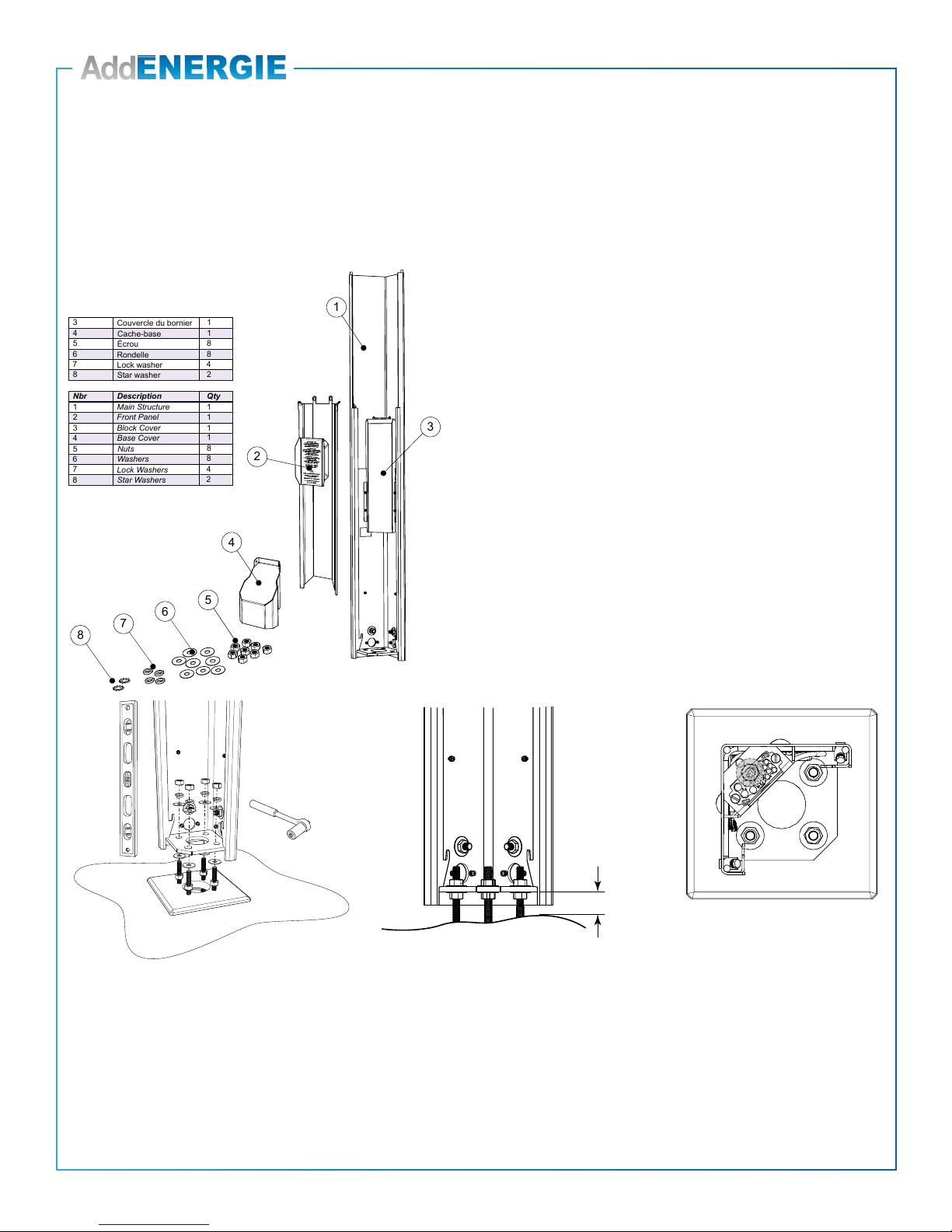
3 cm
(1.125’’)
Vue de dessus
Top view
Pedestal
Single base installation
INSTRUCTIONS:
•Install the main structure over the concrete base.
Make sure to maintain a minimum of 3cm (1.125”)
between the bottom of the structure and the top of
the base.
• Adjust the level of the structure through the nuts
attaching it to the base.
9

10
© 2019 ADDÉNERGIE TECHNOLOGIES INC. ALL RIGHTS RESERVED Information and specications contained in this document are subject to change, amendments and additions at any time, without notice
V20-2019-04-03
Pedestal
Double & quadruple base installation
INSTRUCTIONS:
• Identify which sides of the main structures
must be assembled side to side and remove their
corresponding bolts and joining plates.
• Place the main structures one against the other
and join them together with the 2 bolts you
just removed.
• Assemble a stabilizer into the hole of the main
structure that is not fastened to the threaded
shaft anchor.
• Install the main structure over the concrete base.
Maintain a minimum of 3cm (1.125”) between the
bottom of the structure and the top of the base.
• Adjust the level of the structure through the nuts
attaching it to the base.
3 cm
(1.125’
’)
Vue de dessus
Top view
Piédestal double / Double pedestal
Vue de dessus
Top view
Piédestal quadruple / Quad pedestal
Double pedestal
Quad pedestal
Plaque d’union
Joining Plate
11
© 2019 ADDÉNERGIE TECHNOLOGIES INC. ALL RIGHTS RESERVED Information and specications contained in this document are subject to change, amendments and additions at any time, without notice
V20-2019-04-03
Pedestal
Double & quadruple base installation
For double or quadruple mounting with panel holder (part number: S2-V2-
ACCSPSM-01-02), add spacers (part number: S2-V2-ACCSPSM-01-05) between
the main structures.
Utiliser des boulons plus longs
3.8 cm (1.5’’)
Use longer bolts, 3.8 cm (1.5’’)

12
© 2019 ADDÉNERGIE TECHNOLOGIES INC. ALL RIGHTS RESERVED Information and specications contained in this document are subject to change, amendments and additions at any time, without notice
V20-2019-04-03
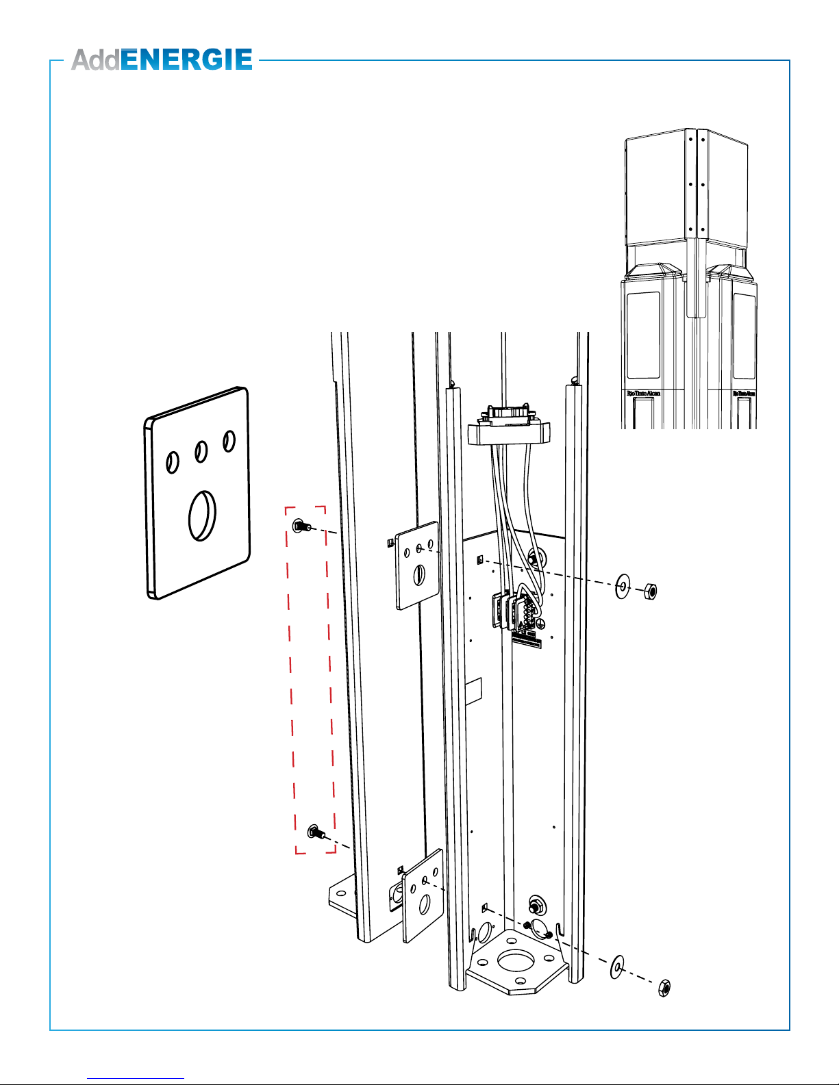
Wall Mount
Single unit installation
INSTRUCTIONS:
• Make sure that the available height is a
minimum of 216cm (85”)
• If the wall requires that anchors to be pre-
installed, follow the drilling pattern provided
on right
• Install the base on the wall using the proper
type of anchors, which means ½-13 inserts
and bolts for a concrete wall, or ½ lag bolts
for a wooden wall.
• Before drilling and during the installation of the
base on the wall, make sure that everything is
leveled
SPECIAL NOTES:
• The EVSE has been assembled at the factory to point toward the right
side, assuming that it will be installed on the left corner of the parking
stall.
• To install on the right corner of the parking stall, the nuts and bolts
attaching the back of the base to its inner frame shall be transferred from
one side to the other as shown on the pictures.
• Make sure you put both longer bolts at the position closest to the terminal
block.
2
3
No
Description
Qté
1
Structure principale
1
1
1
Panneau frontal
Couvercle du bornier
1
3
2
2
3
Nbr
Description
Qty
1
Main Structure
1
1
1
Front Panel
Block Cover
Mon
tage du côté gauch
e
Left side mounting
Mon
tage du côté droi
t
Right side mounting
SOL
GROUND
74 cm
(29’’)
21 cm
(8.25’’)
8.3 cm
(3.25’’)
Patron de perçage:
Drilling pattern:

13
© 2019 ADDÉNERGIE TECHNOLOGIES INC. ALL RIGHTS RESERVED Information and specications contained in this document are subject to change, amendments and additions at any time, without notice
V20-2019-04-03
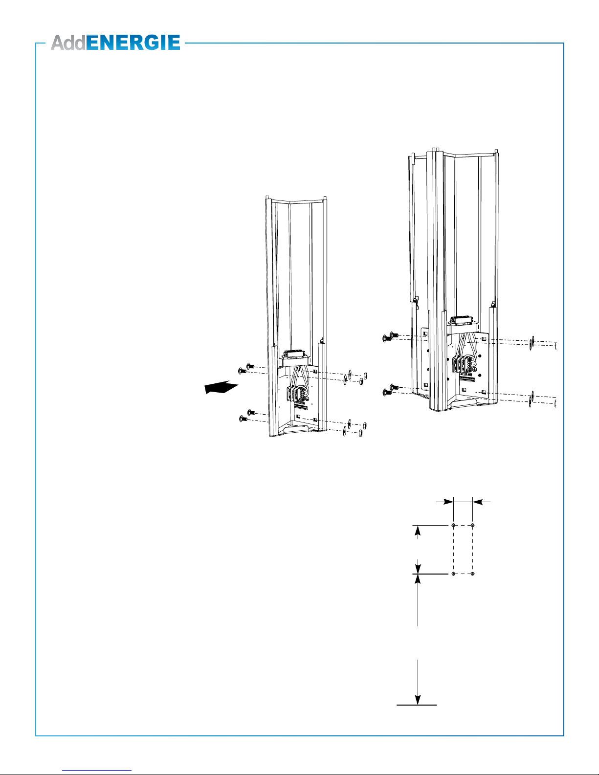
Wall Mount
Double unit installation
For double mounting with panel holder (part number: S2-V2-ACCSPSM-01-02),
add spacers (part number: S2-V2-ACCSPSM-01-05) between the main structures.
Utiliser des boulons plus longs
3.8 cm (1.5’’)
Use longer bolts, 3.8 cm (1.5’’)
14
© 2019 ADDÉNERGIE TECHNOLOGIES INC. ALL RIGHTS RESERVED Information and specications contained in this document are subject to change, amendments and additions at any time, without notice
V20-2019-04-03
Wall Mount
Double unit installation
• Make sure that the available height is a minimum of
216cm (85”)
• If the wall requires that anchors to be pre-installed,
follow the drilling pattern provided on right
• Install the base on the wall using the proper type of
anchors, which means ½-13 inserts and bolts for
a concrete wall, or ½ lag bolts for a wooden wall.
• Before drilling and during the installation of the base
on the wall, make sure that everything is leveled
INSTRUCTIONS:
• Identify which sides of the main structure
must be assembled face to face and
remove their corresponding bolts and
screwed plates.
• Place the main structures one against
the other and join using the four (4)
longest carriage bolts you just removed.
SOL
GROUND
74 cm
(29’’)
21 cm
(8.25’’)
8.3 cm
(3.25’’)
Patron de perçage:
Drilling pattern:
15
© 2019 ADDÉNERGIE TECHNOLOGIES INC. ALL RIGHTS RESERVED Information and specications contained in this document are subject to change, amendments and additions at any time, without notice
V20-2019-04-03
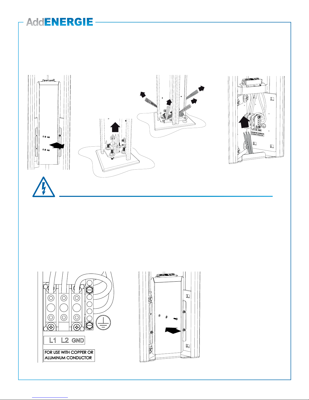
Electrical Connections
Installation and maintenance of this EVSE must only be
performed by a certied electrician to ensure compliance
with local and national codes.
Requires a dedicated 40A dual protection device
(breaker or fuse).
Do not add CCID protection to the service panel. This
kind of protection is already built into AddÉnergie’s
EVSE.
Input: 208/240VAC nominal, 60Hz, 30A
Recommended tightening torque for the block bolts: 18Nm.
Wire size of AWG 2 - 8, copper or aluminium
Le couvercle du bornier doit
être remis en place une fois les
connexions effectuées
Reinstall the block cover once
all connections are made.
IMPORTANT
Piédestal
Pedestal
Mural
Wall-mounted
1
3
2
4
Remove the block cover.
Insert the wires from the bottom of the base and proceed with the connection as shown on the gure below for
each EVSE.
16
© 2019 ADDÉNERGIE TECHNOLOGIES INC. ALL RIGHTS RESERVED Information and specications contained in this document are subject to change, amendments and additions at any time, without notice
V20-2019-04-03
Vue de dessus
Top View
frontaux avec les vis et les rondelles étoilées (star
washer).
Tighten each front panel’s two mounting brackets
with bolts and star washers.
Glisser le panneau frontal en place.
Slide front panels into position.
Vue de dessus
Top View
frontaux avec les vis et les rondelles étoilées (star
washer).
Tighten each front panel’s two mounting brackets
with bolts and star washers.
Glisser le panneau frontal en place.
Slide front panels into position.
Vue de dessus
Top View
frontaux avec les vis et les rondelles étoilées (star
washer).
Tighten each front panel’s two mounting brackets
with bolts and star washers.
Glisser le panneau frontal en place.
Slide front panels into position.
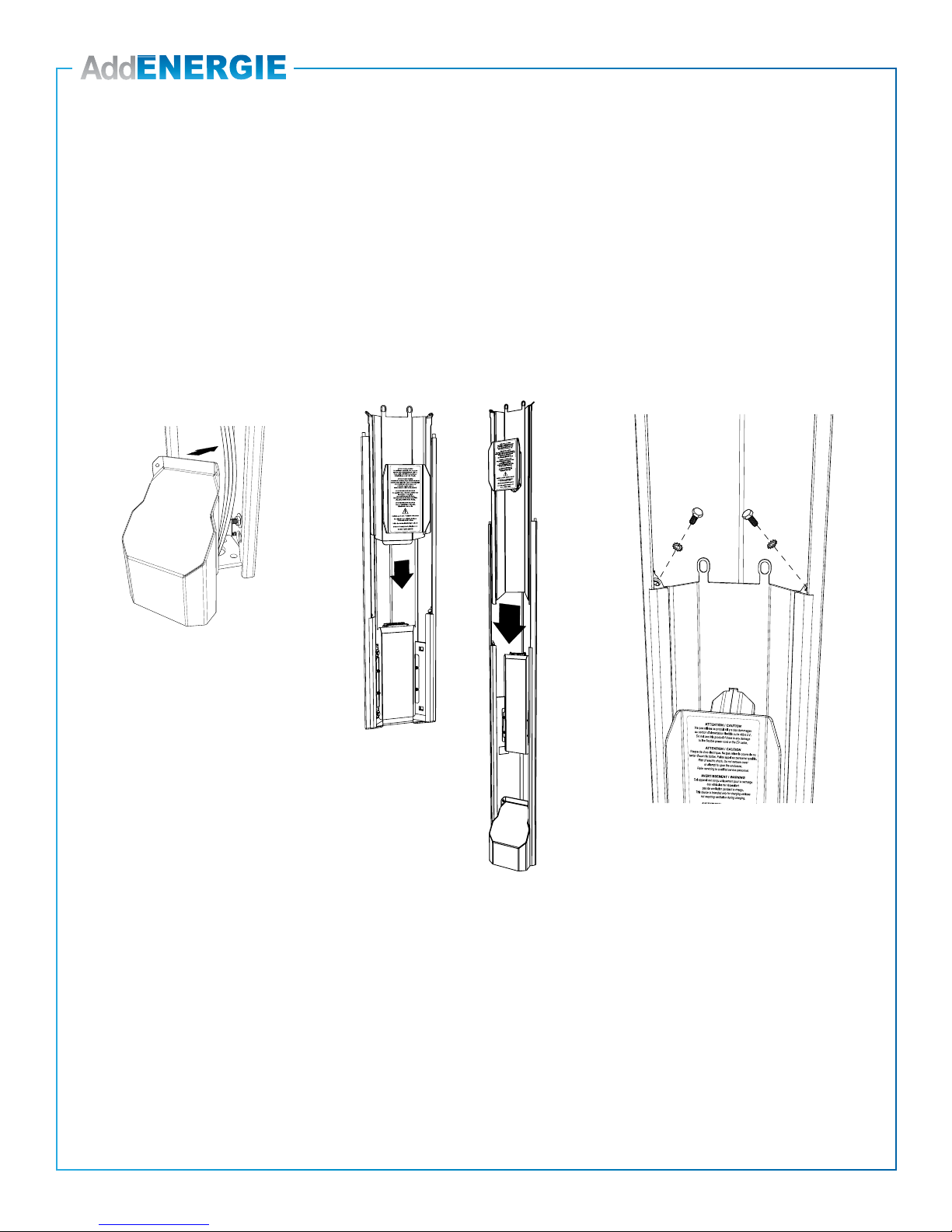
Front Panel & Base Cover Installation
INSTRUCTIONS:
1. For a pedestal installation, insert base covers into each of the main structure
down to the ground and fasten them with the provided hardware.
2. Slide the front panels into each of the main structures.
3. Fasten each front panel’s two mounting brackets with bolts and star washers.
Step 2Step 1 Step 3
17
© 2019 ADDÉNERGIE TECHNOLOGIES INC. ALL RIGHTS RESERVED Information and specications contained in this document are subject to change, amendments and additions at any time, without notice
V20-2019-04-03
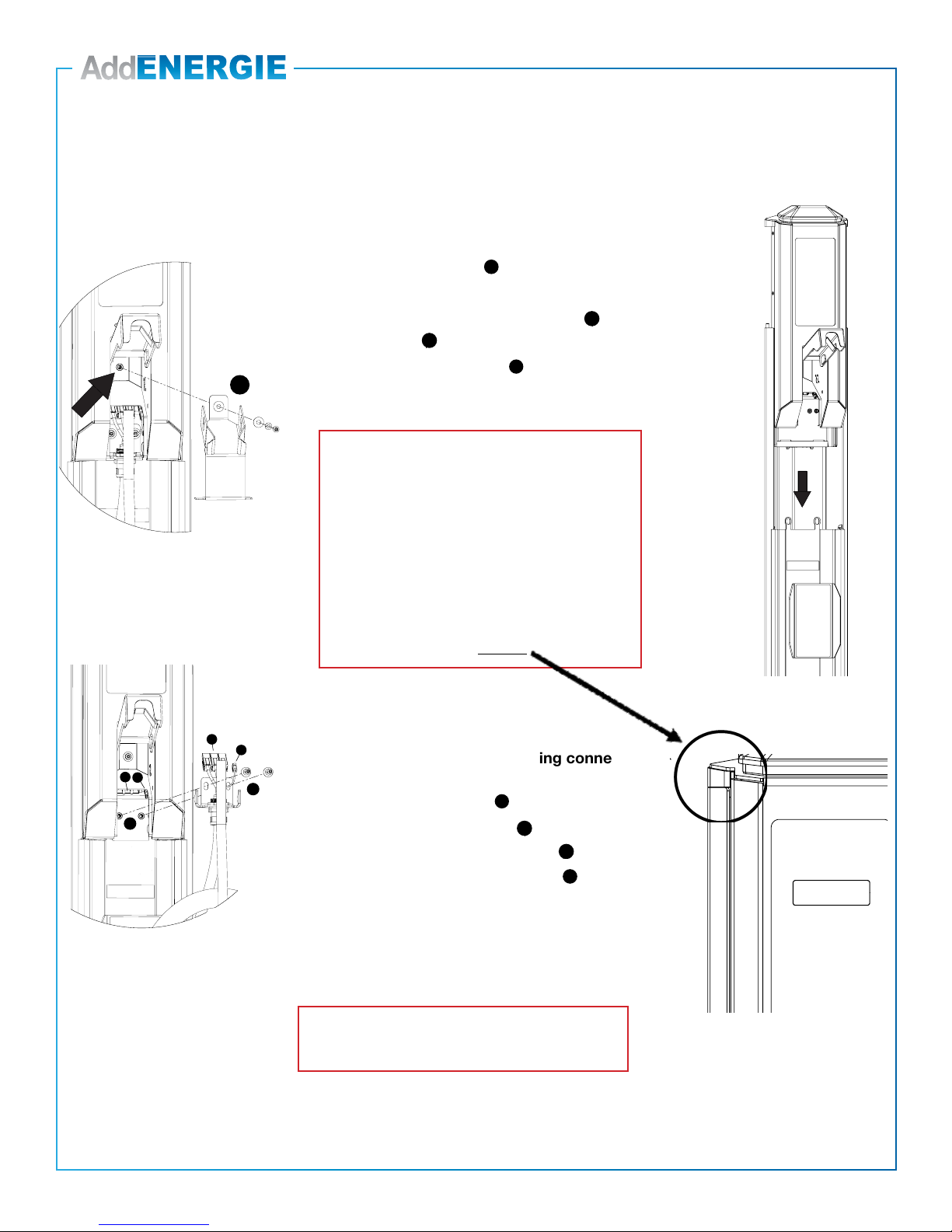
Station Head and Connector Installation
Installation of the charging station head on its base
1. Unscrew the charging port holder .
2. Remove the charging port and cable assembly
2.1 Dsconnect the three positions connector and the small black
connector .
2.2 Unscrew the two brackets .
3. Slide the head into the base
Installation of the charging coupling connector
1. Screw the bracket back into place .
2. Connect the three positions connector (green connection should
be on the right) and the small black connector .
3. Screw the charging port holder back into place .
Make sure the bottom of the charging port holder does not interfere
with the base.
4
1
2
1
2
3
3
Important:
- Do not slide the head down with excessive force. If
the head doesn’t slide down into position easily, gentle
shake the base of the charger head while guiding it into
the base.
- Be careful not to damage the black plastic connectors
on the bottom of the charger head on the top of the
base.
- Once fully inserted, the spacing between the head and
the base should be from 0 à 3mm
*WARNING: Never use a power tool to install the security
screws, and never apply a torque of more than 18Nm
(160 pound-inches) when tightening them.
4
1
2
1
2
3
3
1
2
1
2
3
3
1
2
1
2
3
3
1
2
1
2
3
3
1
2
1
2
3
3
1
2
1
2
3
3
4
18
© 2019 ADDÉNERGIE TECHNOLOGIES INC. ALL RIGHTS RESERVED Information and specications contained in this document are subject to change, amendments and additions at any time, without notice
V20-2019-04-03
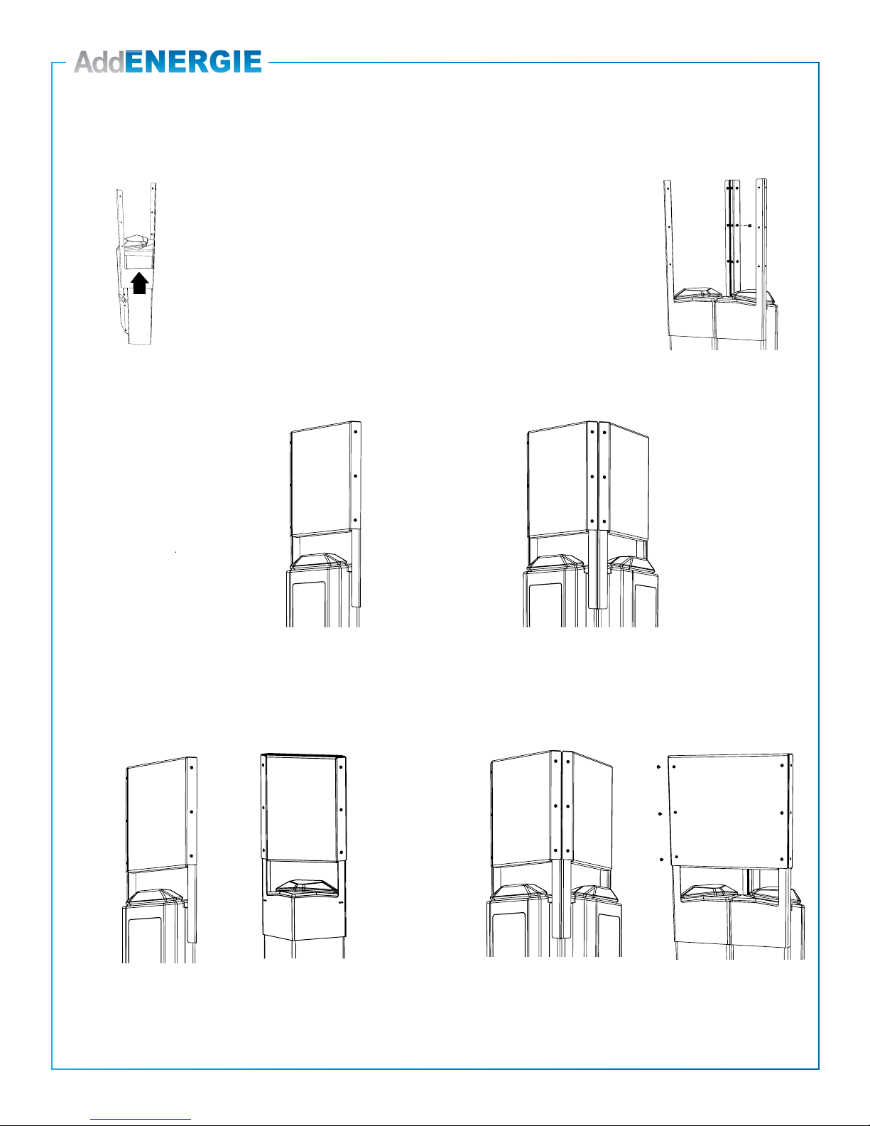
Installation of the Panel on the Charging Head
• Slide the panel holder onto the charging station head as shown in
the image on the left (at this stage, the panel holder is not attached
to the head but simply clipped to it).
• Attach the panel(s) to the panel holder. Only one is required for a wall
mount installation and two are required for a pedestal installation.
• For a double or quadruple installation screw the adjacent panel
holders together, as shown on the image to the right.
WALL MOUNT
PEDESTAL
Simple / Single
2Panels
Double / Double
2Singles Panels + 1 Double Panel
Screw the two panels holders together.
Simple / Single
2Panels
Double / Double
2Singles Panels + 1 Double Panel
Screw the two panels holders together.
Simple / Single
2Panels
Double / Double
2Singles Panels + 1 Double Panel
Screw the two panels holders together.
Simple / Single
2Panels
Double / Double
2Singles Panels + 1 Double Panel
Screw the two panels holders together.
Simple / Single
2Panels
Double / Double
2Singles Panels + 1 Double Panel
Screw the two panels holders together.
Simple / Single
1Panel
Double / Double
2Panels
Single
(1 panel)
Double
(2 panels)
Double
(2 singles panels + 1 double panel)
Single
(2 panels)
19
© 2019 ADDÉNERGIE TECHNOLOGIES INC. ALL RIGHTS RESERVED Information and specications contained in this document are subject to change, amendments and additions at any time, without notice
V20-2019-04-03
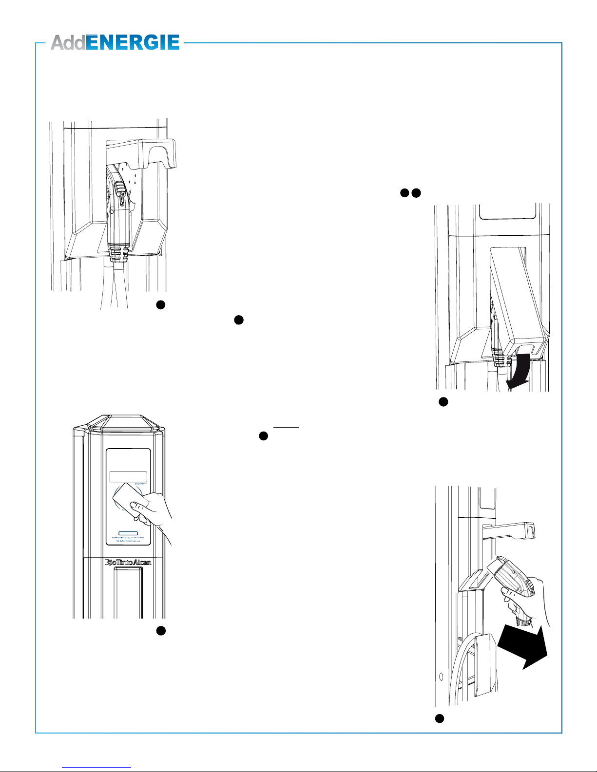
Preliminary Tests & Commissioning
201304-AAA-001
201304-AAA-001
1
2
1
2
3
3
1
2
1
2
3
3
1
2
1
2
3
3
4
Instructions:
1. Place the charging port in the holder and close the door.
2. Once the charging station is powered up, check the following:
2.1. The door is locked.
2.2. The charger head status lights turn to GREEN.
2.3. The display shows the greeting messages.
3. Swipe the card provided with the charger in front of the
display.
The charger will react as follows:
3.1. Once the reader detects the card, it will emit an audible
beep.
3.2. The access card is authenticated by the charging station.
3.3. If the test is successul, the charger head status WHITE
lights will start ashing and the charging port will be
unlocked.
3.4. If the charging port is inserted into an Electrical Vehicle,
it will begin charging. If not, 1 minute later, the charging
session will be cancelled.
4. If the preliminary test is successful:
4.1. Make sure you have installed the Communication
Gateway according to the instructions described in the
“Important” section, on page 2 of this guide.
4.2. Call AddEnergie for charger commissioning:
877-505-2674
1
2
1
2
3
3
1
2
1
2
3
3
1
2
1
2
3
3
4

T. 1 877 505-2674
F. 855 505-2674
addenergie.ca
Installation or commissioning questions:
(877) 505-2674
AddÉnergie Technologies Inc.
Head office: 2800, Louis-Lumière Street, office 100, Québec (QC) G1P 0A4 CANADA
Contact Us
Other manuals for SmartTWO
1
Table of contents
Other AddEnergie Batteries Charger manuals

AddEnergie
AddEnergie FLO SmartDC User manual

AddEnergie
AddEnergie SmartDC-V2 User manual

AddEnergie
AddEnergie CoRe+ C+V1-PED-ADD User manual

AddEnergie
AddEnergie CoRe+ Instruction Manual

AddEnergie
AddEnergie CoRe+V2 User manual

AddEnergie
AddEnergie SmartDC User manual

AddEnergie
AddEnergie SmartTWO User manual


