manuals.online logo
Brands
  1. Home
  2. •
  3. Brands
  4. •
  5. ADTRAN
  6. •
  7. Network Hardware
  8. •
  9. ADTRAN T200 HTU-R User manual

ADTRAN T200 HTU-R User manual

C A U T I O N !
SUBJECT TO ELECTROSTATIC DAMAGE
OR DECREASE IN RELIABILITY.
HANDLING PRECAUTIONS REQUIRED.
For more information, refer to the Installation and Maintenance Practice (P/N 61247026L1-5) available online at www.adtran.com.
©2007 ADTRAN, Inc.
All Rights Reserved.
HDSL
T200 HTU-R
P/N: 1247026L1
CLEI: T1I3AAVA_ _
*61247026L1-22A*
♦Manual Update Mode: Press the space bar three times to manually update the screen. Print
Screen and Log File commands are available in this mode.
♦Real-Time Update Mode (Default): Print Screen and Log File commands are not available
in this mode. Cursor placement and screen highlighting are enabled.
Provision Terminal Port for VT100
♦Data Rate = 1.2 kbps to 19.2 kbps
♦Asynchronous Data Format = 8 data bits, no parity (none), 1 stop bit, and no flow control
NOTE: When using a PC with terminal software, disable any power saving programs.
OPTION SETTINGS DISPLAY
1. External option only available when using 220 HTU-C (1247001L6). It is the default
option setting when used with this form factor.
2. The 01 - 24 should be one line. DS0 Blocking (XX = Blocked): 01 02 03 04 05 06 07 08 09
10 11 12 13 14 15 16 17 18 19 20 21 22 23 24
3. Shelf Alarm only available when using DDM+ HTU-C or 3192 (124x003L6 or
124x004L6).
4. Span Power is an option that is only valid for the HTU-C and will not display on the HTU-
R user interface.
OPTION JUMPER
P3 sets the DS1 NIU 60 mA Current Setting as follows:
♦Off disables the constant current source for the DS1 NIU.
♦On Enables the 60 mA constant current source for the DS1 NIU.
INSTALLATION AND TURN-UP
After unpacking the unit, inspect it for damage. If damage is noted, file a claim with the
carrier and then contact ADTRAN. Refer to Warranty.
NOTE: This unit can be provisioned via the RS-232 port or remotely via inband codes.
1. Set the option jumper according to the specific circuit design.
2. Install the HTU-C and HTU-R.
Description Settings Default
DSX-1 Transmit Level 0, 133, 266, 399, 533, EXT (1) 0
Line Code AMI, B8ZS B8ZS
DSX-1 Framing AUTO, UNF, ESF, SF, Forced Conversion AUTO
NIU Loopback EN, DIS EN
New England 1:6 LPBK EN, DIS DIS
Loopback Timeout NONE, 60 MIN, 120 MIN 120 MIN
Customer Loss Response AIS, CDI, LPBK AIS
Latching Loopback Mode T1, FT1 T1
Performance Reporting Message NPRM, SPRM, NONE, AUTO AUTO
DS1 Transmit Level (2) 0 dB, –15 dB 0 dB
Shelf Alarm (3) EN, DIS EN
Span Power (4) EN, DIS EN
FRONT PANEL LEDS
PUSHBUTTON LOOPBACK FUNCTIONS (LBK)
♦LOC: Initiates bidirectional loopback of HTU-R toward the network and customer
♦REM: Initiates loopback at the HTU-C toward the customer
DS1 MONITORING (BANTAM) JACK (MON)
The front panel of the HTU-R contains a metallic bantam jack for DS1 test access.
Monitor
If the DS1 test set is optioned for MONITORING, the monitor jack provides a non-
intrusive tap onto the signal line.
♦TX: Monitors the data stream being transmitted to the network from the customer
♦RX: Monitors the data stream that would be received from the network to the customer
DB-9 CONNECTOR (RS-232)
The DB-9 connector on the front panel is an RS-232 craft interface port for connection to
a terminal emulator. Use a VT100 or equivalent terminal and a terminal application such
as HyperTerminal (Private Edition) to access performance monitoring data, enable
loopbacks, and provision the unit.
There are two types of terminal emulation modes: Manual Update Mode and Real-Time
Update Mode. Use CTRL+T to toggle between the two terminal emulation modes.
Label Status Description
DSL1/
DSL2
{
z
z
z
5
Off
Green
Yellow
Red
Flashing
No synchronization
Signal quality good (4 to 9)
Signal quality marginal (1 to 3)
Signal quality poor (0)
Error detected at HTU-C or HTU-R. The color, when
flashing, indicates loop signal quality
DS1 {
2
z
Off
Green Flashing
Green
DS1 signal not detected from customer or format does not
matching HDSL circuit provisioning
BPV/frame error (SF)/CRC error detected (ESF)
DS1 signal is present and synchronized
ALM {
z
z
Off
Yellow
Red
No alarm condition detected
Remote alarm condition (HTU-C) detected
Local alarm condition (HTU-R) detected
ESF/SF {
z
z
Off
Green
Yellow
Unframed mode
Unit is currently receiving SF data
Unit is currently receiving ESF data
B8ZS/AMI z
z
Green
Yellow
DS1 provisioned for AMI line coding
DS1 provisioned for B8ZS line coding
LLB/RLB {
z
2
z
Off
Green
Yellow Flashing
Yellow
Unit not in loopback or armed state
Active remote loopback from the HTU-C toward the cus-
tomer and/or network
Unit armed, but not in active loopback condition
Active local loopback from the HTU-R toward the cus-
tomer and/or network
61247026L1-22A
0708
HDSL
T200 HTU-R, Span Powered, 60 mA
PRICING AND AVAILABILITY 800.827.0807
TECH SUPPORT 800.726.8663
RETURN FOR REPAIR 256.963.8722
www.adtran.com
61247026L1-22A
Warranty: ADTRAN will replace or repair this product within the warranty period if it does not meet its published specifications or fails while in service.
Warranty information can be found online at www.adtran.com/warranty.
3. The DSL1/DSL2 LED should be green on the HTU-C and HTU-R. The DSX LED should be green on
the HTU-C and the DS1 LED should be green on the HTU-R. The ALM LED on both units should be
dark.
• HTU-C displays LLOS if not connected to network (no DSX present; LED solid red).
• HTU-R has red ALM LED if customer not connected. LP1, LP2, line coding (B8ZS or AMI) and
framing (ESF or SF) (if not UNFR) LEDs should light.
4. If the Status LED is green, do the following:
• Verify that the signal quality is the same on each loop. Ensure signal quality indicators do not fluctuate.
• Verify that the loop loss is within design limits. If there is a difference of more than 1 dB between the
two loops, a problem exists with the cable pairs.
• If errors occur, use the Current System Status and Performance History screens to determine where they
are occurring. For more information, refer to “Troubleshooting”.
5. If everything checks out, proceed with BERT testing.
EDGE PIN ASSIGNMENTS
TROUBLESHOOTING
The HTU-C ALM LED is yellow, but no errors are indicated by the HTU-R:
♦A BPV, Frame error (SF) or CRC error (ESF) was detected at the DSX-1 interface. This indicates a possible
network or wiring problem between the HTU-C and the DSX. This does not indicate problems on the
HDSL loops.
The HTU-R DS1 LED is flashing, but the HTU-C indicates no errors:
♦A BPV, Frame Error (SF) or CRC Error (ESF) was detected at the DS1 interface. This indicates a
Frequency Maximum (Hz) Loss Data (dB) wiring problem, or a B8ZS/AMI mismatch between the
HTU-R and the customer equipment. This does not indicate problems on the HDSL loops.
The HTU-R has power, but the DSL1/DSL2 LEDs are dark. The unit cannot sync with the HTU-C:
♦Simplex power for powering the HTU-R can be passed over cable pairs that contain load coils or that are
too long for HDSL synchronization. Using a TIMS, verify the circuit is within design limits.
♦The HTU-R will power up if there is at least one good conductor on each loop. To test, remove the protector
plug at the MDF and measure t-r resistance to the HTU-R on both loops. The HTU-R places a 3-ohm short
between t-r on both loops. An extremely high impedance indicates an open conductor. An extremely low
reading on one loop may indicate a t-r short in the field. In the field, measure t-t and t-r voltage with the
Pin Designation Description
1, 11, 27 CH GND Chassis ground
5DS1-T1 DS1 receive out tip (to customer interface)
7H1-T HDSL Loop 1 tip (facility)
12 GND Ground for protection switching
13 H1-R HDSL Loop 1 ring (facility)
15 DS1-R1 DS1 receive out ring (to customer interface)
20 VCC +5 VDC for protection switching
40 PROT-1 Control line for protection switching
41 H2-T HDSL Loop 2 tip (facility)
47 H2-R HDSL Loop 2 ring (facility)
49 DS1-R DS1 transmit in ring (from customer interface)
HTU-C installed and compare to the t-t voltage chart. The absence of these voltages indicates open pairs or
mis-wiring. As with other circuits, use standard resistance measurements between each conductor and
ground to test for a grounded conductor.
♦A high resistance open that degrades to where it causes the circuit to lose sync can be “resealed” by
reseating the HTU-C. Test the cable pairs before reseating the HTU-C.
Running excessive errors on the loop:
♦Measure t-r resistance (refer to above). If the pairs are unbalanced by more than 4 ohms, or a measurement
varies significantly, this could indicate a high resistance open or an intermittent fault on the loop with the
higher measurement. A TDR is typically required to locate this splice for repair.
♦Excessively long bridged taps can also cause errors. Check the records and/or use a TDR to verify the
location and length of bridged taps.
♦Using the Performance History screen, it is often possible to see that many more errors are being received
on a particular loop or at a particular unit. The fault will typically be very close to the unit receiving the
most errors.
No power at the HTU-R:
♦This could be caused by a loop with two open conductors. Measure t-r resistance from the MDF to the
HTU-R or use the voltage chart to see which pair is open.
Circuit Parameters Under Normal Operation
♦LOSS ≤30 dB
♦Signal quality ≥4 (DSL1/DSL2 LEDs green), with no fluctuation and equal on both loops
♦All HDSL Deployment Guidelines are met
HDSL DEPLOYMENT GUIDELINES
♦Cable pairs must be non-loaded
♦Total bridged tap length < 2.5 kft
♦No single bridged tap > 2 kft
♦196 kHz insertion loss ≤35dB
♦Pulse attenuation (LOSS on HDSL current system status screen) ≤30dB
♦Maximum loop resistance is 130 Ω
♦Impulse noises ≤50 dBrn, as measured using a 50 kb filter
♦Wideband noise ≤ 31 dBrn, as measured using a 50 kb filter
COMPLIANCE
Refer to the HDSL T200 HTU-R, Span Powered, 60 mA Compliance Notice (P/N 61247026L1-17) for
detailed compliance information.
HDSL
T200 HTU-R, Span Powered, 60 mA
Other manuals for T200 HTU-R

2

This manual suits for next models

1

Other ADTRAN Network Hardware manuals

ADTRAN NetVanta Serial Dial Backup Interface Module (DIM)... User manual

ADTRAN

ADTRAN NetVanta Serial Dial Backup Interface Module (DIM)... User manual

ADTRAN Total Access 1500 Total Reach DDS-DP User manual

ADTRAN

ADTRAN Total Access 1500 Total Reach DDS-DP User manual

ADTRAN T1 Nx64 HTU-R Instruction Manual

ADTRAN

ADTRAN T1 Nx64 HTU-R Instruction Manual

ADTRAN GPON 452 User manual

ADTRAN

ADTRAN GPON 452 User manual

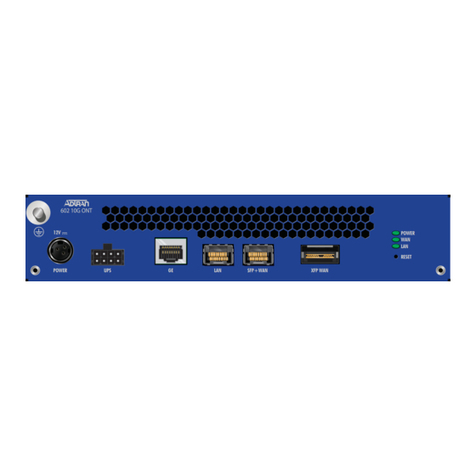
ADTRAN 602 User manual

ADTRAN

ADTRAN 602 User manual

ADTRAN TR OCU DP Instruction Manual

ADTRAN

ADTRAN TR OCU DP Instruction Manual

ADTRAN 3192 User manual

ADTRAN

ADTRAN 3192 User manual

ADTRAN jobAid User manual

ADTRAN

ADTRAN jobAid User manual

ADTRAN 1442120G1 User manual

ADTRAN

ADTRAN 1442120G1 User manual

ADTRAN ENHANCED PSD 239 H2R User manual

ADTRAN

ADTRAN ENHANCED PSD 239 H2R User manual

ADTRAN DSU 5600 User manual

ADTRAN

ADTRAN DSU 5600 User manual

ADTRAN HDSL4 Instruction Manual

ADTRAN

ADTRAN HDSL4 Instruction Manual

ADTRAN DSU IV ESP User manual

ADTRAN

ADTRAN DSU IV ESP User manual

ADTRAN T200 IDSL Instruction Manual

ADTRAN

ADTRAN T200 IDSL Instruction Manual

ADTRAN SHDSL V.35 LTU User manual

ADTRAN

ADTRAN SHDSL V.35 LTU User manual

ADTRAN 4202023L1 User manual

ADTRAN

ADTRAN 4202023L1 User manual

ADTRAN TSU ACE Service manual

ADTRAN

ADTRAN TSU ACE Service manual

ADTRAN SFP User manual

ADTRAN

ADTRAN SFP User manual

ADTRAN DDM+ HTU-C M User manual

ADTRAN

ADTRAN DDM+ HTU-C M User manual

ADTRAN 1442300G1 User manual

ADTRAN

ADTRAN 1442300G1 User manual

ADTRAN TSU ACE User manual

ADTRAN

ADTRAN TSU ACE User manual

ADTRAN 401 1 GE Micro ONT User manual

ADTRAN

ADTRAN 401 1 GE Micro ONT User manual

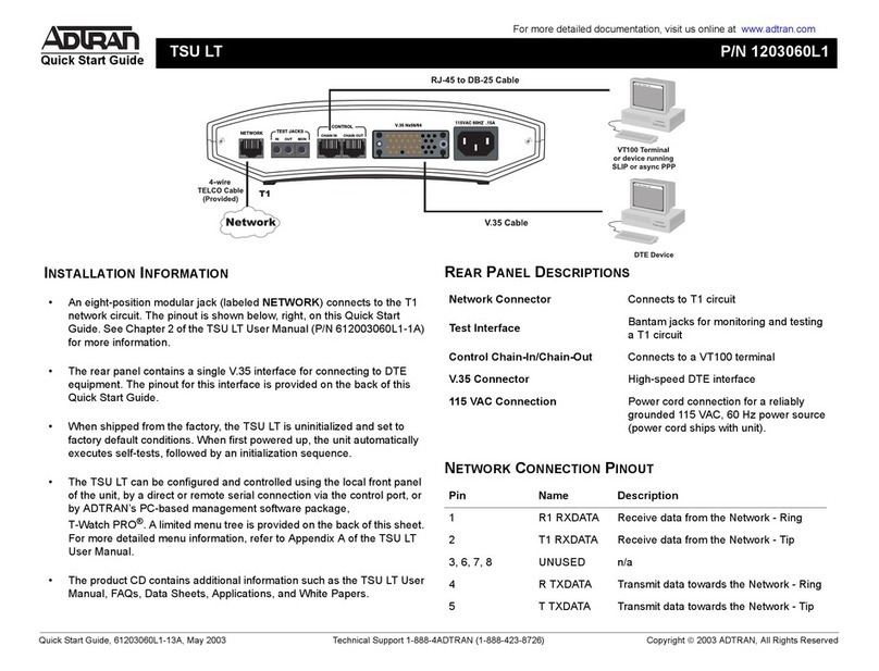
ADTRAN 1203060L1 User manual

ADTRAN

ADTRAN 1203060L1 User manual

ADTRAN Bluesocket 1700900F1 User manual

ADTRAN

ADTRAN Bluesocket 1700900F1 User manual

Popular Network Hardware manuals by other brands

Clearfield FieldSmart 96 Port PON installation manual

Clearfield

Clearfield FieldSmart 96 Port PON installation manual

Cisco NCS 6008 LCC Installing

Cisco

Cisco NCS 6008 LCC Installing

Quantum B DLTSAGE SELLSHEET manual

Quantum

Quantum B DLTSAGE SELLSHEET manual

Kramer TBUS-201 user manual

Kramer

Kramer TBUS-201 user manual

Siemon HD5 instructions

Siemon

Siemon HD5 instructions

Chatsworth Products RIM-600 user manual

Chatsworth Products

Chatsworth Products RIM-600 user manual

Omnitron Systems Technology iConverter 2Tx user manual

Omnitron Systems Technology

Omnitron Systems Technology iConverter 2Tx user manual

Patton electronics Model 2604 Administrator's reference guide

Patton electronics

Patton electronics Model 2604 Administrator's reference guide

Huawei Lampsite RHUB3908 Maintenance Guide

Huawei

Huawei Lampsite RHUB3908 Maintenance Guide

Kiloview CUBE X1 quick start guide

Kiloview

Kiloview CUBE X1 quick start guide

Vivotek ND9541P user manual

Vivotek

Vivotek ND9541P user manual

Lenze E84AZESM Series Mounting instructions

Lenze

Lenze E84AZESM Series Mounting instructions

GIGA G4200 Series quick start guide

GIGA

GIGA G4200 Series quick start guide

Paradyne ACCULINK 316x Operator's guide

Paradyne

Paradyne ACCULINK 316x Operator's guide

Cisco CX-TRIP2 Installation and configuration guide

Cisco

Cisco CX-TRIP2 Installation and configuration guide

Maiwe MT8110 quick start guide

Maiwe

Maiwe MT8110 quick start guide

COMBA TB-1800 Equipment manual

COMBA

COMBA TB-1800 Equipment manual

Huawei CR52-2xPOS/STM16-SFP Specifications

Huawei

Huawei CR52-2xPOS/STM16-SFP Specifications

manuals.online logo
manuals.online logoBrands
  • About & Mission
  • Contact us
  • Privacy Policy
  • Terms and Conditions

Copyright 2025 Manuals.Online. All Rights Reserved.