Advanced Instruments OsmoTECH PRO User manual

OsmoTECH®PRO
Multi-Sample Micro-Osmometer
Service Guide
222006EN Rev 2

2
OsmoTECH PRO Multi-Sample Micro-Osmometer Service Guide
Copyright and trademarks
© 2021 Advanced Instruments
This guide is copyrighted by Advanced Instruments with all rights reserved. Under copyright laws, this guide may not be
reproduced in any form, in whole or part, without the prior written consent of Advanced Instruments. The following are
trademarks of Advanced Instruments:
• OsmoTECH®
• Protinol™
• Clinitrol™
• Renol™
Employees of Advanced Instruments have reviewed this guide thoroughly. Although material contained within is believed
reliable, the accuracy and completeness are not guaranteed or warranted, and are not intended to be representations or
warranties concerning the product described. Screenshots and images included in this guide are for purposes of example
only and may not be an exact match with the screens you see.

3
OsmoTECH PRO Multi-Sample Micro-Osmometer Service Guide
Contents
Contents.............................................................................3
Contacting Advanced Instruments..............................5
Supplies, Standards, and Controls...............................6
Safe Use .............................................................................7
Quality control................................................................. 11
Chapter 1: Overview ...................................................... 13
1.1 Product description ........................................................................ 13
1.2 Front view ........................................................................................... 13
1.3 Rear view............................................................................................. 13
1.4 Mechanical description.................................................................. 14
1.5 Electrical description...................................................................... 14
Chapter 2: Setup............................................................ 16
2.1 Location requirements................................................................... 16
2.2 Unpacking (first time setup)........................................................ 16
Reporting missing or damaged items.................................. 16
2.3 Setting up the instrument..............................................................17
2.4 Connecting to a network (optional)..........................................17
2.5 Powering up the instrument.........................................................17
Setting the installation date (Administrators only) .........17
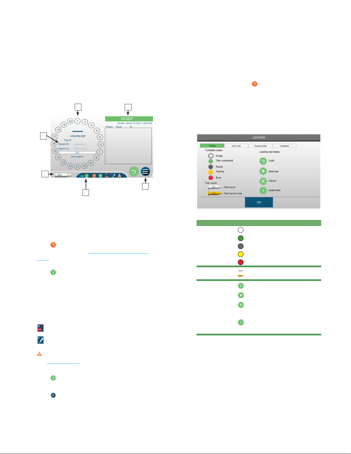
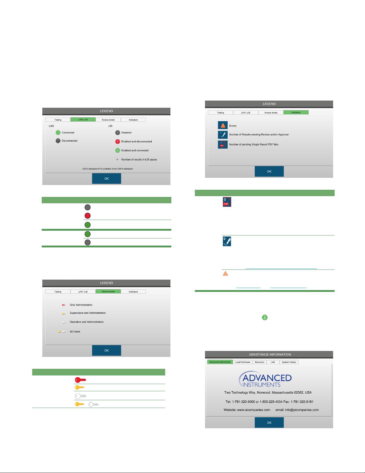
Understanding the status icons.............................................. 18
Viewing instrument assistance information....................... 19
2.6 The main menu.................................................................................20
Chapter 3: Calibration...................................................22
3.1 When to calibrate the instrument..............................................22
0and2000mOsm/kg H₂O calibration (optional)......... 23
Failed calibration......................................................................... 24
3.3 Canceling calibration..................................................................... 24
3.4 Aligning the turntable................................................................... 24
Verifying the turntable alignment......................................... 25
3.5 Checking the positioning of the sample probe and cooling
assembly............................................................................................. 25
Verifying sample probe positioning..................................... 25
Chapter 4: Diagnostics................................................ 26
4.1 Accessing the DIAGNOSTICS menu ........................................ 26
4.2 Testing the analog-to-digital converter ................................. 26
4.3 Testing the sample and block motors ....................................27
Testing the sample motor .........................................................27
Testing the block motor.............................................................27
Testing a wipe process...............................................................27
Testing the turntable motor .....................................................27
4.4 Checking a test card...................................................................... 28
4.5 Testing and cleaning the sample probe ................................. 28
Testing the sample probe ........................................................ 28
Cleaning the sample probe ..................................................... 28
4.6 Testing the barcode scanner ...................................................... 28
4.7 Reviewing and exporting events............................................... 29
Filtering the events list.............................................................. 29
Exporting the events .................................................................30
4.8 Testing the printer .......................................................................... 30
4.9 Testing the screen...........................................................................30
Checking pixels on the screen ...............................................30
Testing the screen brightness ................................................ 30
4.10 Testing the solenoid.......................................................................30
4.11 Logging instrument maintenance and repair ....................... 31
Logging routine instrument cleaning................................... 31
Logging preventative maintenance (Administrators
only) .................................................................................................. 31
Logging repair information (Administrator/Service users
only) ................................................................................................. 32
Chapter 5: Configuring settings.................................33
5.1 The SETTINGS screen.................................................................... 33
Default user accounts................................................................ 33
5.2 Setting the date and time............................................................ 33
Synchronizing to a network time server ............................ 33
Entering the date and time manually.................................. 34
Changing the screen brightness ........................................... 34
Turning on the barcode scanner ........................................... 34
5.3 Changing the probe resistance ................................................. 35
5.4 Setting up networking communications................................ 35
Configuring a LAN connection .............................................. 35
Setting up OPC-UA communication.................................... 36
Enabling the web server........................................................... 36
Viewing and printing data from the webserver............. 36
Connecting to a LIS.....................................................................37
Send-results mode.......................................................................37

Contents
4
OsmoTECH PRO Multi-Sample Micro-Osmometer Service Guide
5.5 Updating the instrument.............................................................. 38
Resetting instrument system settings (Service account
only) ................................................................................................. 39
Configuring V&V settings (Service account only) ........ 39
5.6 Managing instrument data ..........................................................40
Exporting data .............................................................................40
Backing up the database .......................................................... 41
Configuring data recording (Administrators only) ........ 42
Importing/restoring database records (Administrators
only)...................................................................................... 42
Preparing to import from a USB drive ...........................42
Preparing to import from a network folder .................42
Importing the data ...............................................................43
Exporting results ......................................................................... 43
5.7 Assigning user restrictions..........................................................44
Changing password settings .................................................. 45
Configuring testing access...................................................... 46
Configuring audits of test results (approvals, reviews,
and comments) ............................................................................46
Setting timeouts.......................................................................... 47
Chapter 6: Maintenance and Service ....................... 48
6.1 Who should perform service?.................................................... 48
6.1 Maintenance...................................................................................... 48
Daily maintenance ...................................................................... 48
Weekly maintenance:.................................................................49
Monthly maintenance: ...............................................................49
Semi-annual maintenance:....................................................... 49
Annual maintenance: .................................................................50
6.2 Shutdown and storage.................................................................. 50
Overnight or weekend:..............................................................50
One week or longer:................................................................... 50
Chapter 7: Troubleshooting ........................................ 51
7.3 Fatal errors ......................................................................................... 51
Non-fatal errors............................................................................. 51
Sample test errors........................................................................52
7.1 General errors....................................................................................52
7.2 Errors during calibration .............................................................. 53
Appendix A: Product specifications .........................55
Appendix B: Performance characteristics .............. 56
Appendix C: OPC-UA Features and Configuration57
C.1 OPC-UA overview ............................................................................57
Functional equivalence ..............................................................57
Cross-platform support .............................................................57
Security ............................................................................................57
Information modeling.................................................................57
C.2 OPC-UA implementation ............................................................. 58
C.3 Example of OPC remote use/workflow.................................. 58
Requirements................................................................................ 58
Supported OPC Features........................................................ 58
Example of a Remote OPC Setup......................................... 59
JSON output: ...............................................................................60
Appendix D: OsmoTECH PRO LIS Specification.... 61
D.1 Purpose................................................................................................ 61
D.2 Overview.............................................................................................. 61
D.3 Basic operation ................................................................................. 61
D.4 Low-level protocol.......................................................................... 62
D.5 Message layer ................................................................................... 63
D.6 Header record................................................................................... 64
D.7 Sample information record .........................................................64
D.8 Test order record.............................................................................64
D.9 Result record..................................................................................... 65
Appendix E: Regulatory notices ................................67
Appendix F: System Schematic................................. 69
Appendix G: Product Disposal and Recycling....... 70
Appendix H: Known Limitations ................................ 71
Appendix I: Service Log...............................................72
Appendix J: Replacement Parts.................................74

5
OsmoTECH PRO Multi-Sample Micro-Osmometer Service Guide
Contacting Advanced Instruments
General inquiries
US or Canada
• Phone: 800-225-4034 from 8:00 AM – 4:30 PM Eastern time
Outside US or Canada:
• Phone: +1 781-320-9000
• Email: info@aicompanies.com
• Web: aicompanies.com
Customer Service/Orders
US or Canada
• Phone: 800-225-4034 from 8:00 AM – 4:30 PM Eastern time
Outside US or Canada
• Phone: +1 781-320-9000
• Email: orders@aicompanies.com
Technical Service
US or Canada
• Phone: 800-225-4034 from 8:00 AM – 4:30 PM Eastern time;
after normal business hours, follow prompts
Outside US or Canada:
• Phone: +1 781-320-9000
• Email: techsupport@aicompanies.com
NOTE: When contacting Advanced Instruments for technical support, please be ready to provide the service technician with
the model and the serial number of the instrument, as well as a general description of the problem. It may be
necessary to perform diagnostic checks during the service call, so please contact us from a telephone that allows you
immediate access to the instrument. A service technician may verbally assist you with making minor repairs, may
provide you with information regarding recommended parts or part numbers, and/or may issue you a Return
Merchandise Authorization (RMA) to ship the instrument to us for factory repairs. The RMA procedure is as follows:
1. Contact Advanced Instruments to obtain an RMA.
2. Pack and ship the instrument in its original carton. Do not include instrument supply items.
3. Prepay shipment to the factory. Advanced Instruments cannot accept collect shipments.
4. Insure the shipment or accept the risk of potential damage.

6
OsmoTECH PRO Multi-Sample Micro-Osmometer Service Guide
Supplies, Standards, and Controls
NOTICE: Use of consumable products—including
sample tubes, controls or calibrators—from other
manufacturers will impact the instrument warranty.
For information on references and controls, see Quality
control in the user guide.
To order supplies, standards, and controls, contact the
Advanced Instruments Customer Service Department
(see Contacting Advanced Instruments).
General supplies
Item Part Number
Disposable sample tubes 222825
Probe wiper rings 222840
30-μL pipette 222820
Pipette tips 800097
Swab cleaner kit 202850
Replacement evaporation cover 222081
Replacement turntable 112077
Replacement sample probe 222140R
OsmoTECH PRO User Guide USB drive 222005UG
OsmoTECH PRO Service Guide USB drive 222006SM
Calibration standards
Item Part Number
0 mOsm/kg Calibration Standard
(ten 2-mL ampules)
3MA000
50 mOsm/kg Calibration Standard
(ten 2-mL ampules)
3MA005
850 mOsm/kg Calibration Standard
(ten 2-mL ampules)
3MA085
2000 mOsm/kg Calibration Standard
(ten 2-mL ampules)
3MA200
Reference solutions and controls
Item Part Number
Clinitrol™ 290 Reference Solution
(ten 2-mL ampules)
3MA029
Osmolality Linearity Set (5 levels) 3LA028
Protinol™ Protein-Based Serum Controls
(3levels)
3MA028
Other standards
Item Part Number
100 mOsm/kg Calibration Standard
(ten 5-mL ampules)
3LA011
200 mOsm/kg Calibration Standard
(ten 2-mL ampules)
3MA020
400 mOsm/kg Calibration Standard
(ten 2-mL ampules)
3MA040
500 mOsm/kg Calibration Standard
(ten 5-mL ampules)
3LA051
900 mOsm/kg Calibration Standard
(ten 5-mL ampules)
3LA091
1000 mOsm/kg Calibration Standard
(ten 2-mL ampules)
3MA100
1500 mOsm/kg Calibration Standard
(ten 5-mL ampules)
3LA151
NOTICE: Advanced Instruments cannot
guarantee the stated instrument performance
specifications and accuracy of test results
unless Advanced Instruments brand
consumables are used with the instrument.
Use of consumables from manufacturers other
than Advanced Instruments is not
recommended and may adversely aect
system calibration, performance, operation,
and accuracy of test results.
Sample tips and cleaners are single-use
consumables; sample cross-contamination can
occur if sample tips and cleaners are re-used.
For information on obtaining these standards
and controls, see Contacting Advanced
Instruments.

7
OsmoTECH PRO Multi-Sample Micro-Osmometer Service Guide
Safe Use
WARNING: To reduce the risk of bodily injury, electric shock, fire, and damage to the instrument, please read and
observe all precautions in this guide.
Only operate this product in accordance with the equipment design, operating instructions, and manufacturer
recommendations; to do otherwise may impair the instrument function or create a safety hazard.
Do not attempt to perform electrical work if you are not fully qualified. This manual is not a substitute for electrical
training.
General cautions
• Only power this instrument with the source specified
on the product electrical ratings label. Refer to Setup.
• If the power cord provided is replaced for any reason
or if an alternate cord is used, the cord must be
approved for use in the local country. The power cord
must be approved for the product’s listed operating
voltage and must be rated at least 20% greater than
the volt-ampere (VA) ratings marked on the product’s
electrical ratings label. The cord end that connects to
the product must have an IEC 60320 connector.
• Plug the product into an approved grounded electrical
outlet. Exposure to AC voltage could lead to electric
shock, burn, or electrocution. Please be aware of any
exposure of AC voltage in the power cord.
• Do not disable the power cord grounding pin.
• If an extension cord or power strip is used, make sure
that the cord or strip is rated for the product and that
the total ampere ratings of all products plugged into
the extension cord or strip do not exceed 80% of the
cord or strip rating limit.
• Route power cords so that they will not be walked on,
tripped on, or pinched by items placed upon or
against them. Pay particular attention to the plug,
electrical outlet, and the point where the cord exits the
product.
• Do not pull on cords and cables; grasp the
corresponding connector to unplug it.
• Do not install or use this product in any area subject to
extreme short-term temperature variations, or in
locations that exceed the specified operating
environment temperatures.
• Never use this product in a wet area.
• To avoid injury or fire hazard, do not operate this
product in an explosive atmosphere.
• Do not install or use the product on an unstable,
non-level work surface.
• Do not operate this product with the covers removed
or unsecured.

Safe Use
8
OsmoTECH PRO Multi-Sample Micro-Osmometer Service Guide
Service and maintenance cautions
• Unplug the power cord before opening or removing
the covers; otherwise, you may be exposed to electric
shock, excessive temperatures, or mechanical hazards.
• Any service or maintenance not covered in this guide
should only be performed by a qualified service
technician.
• Never restrict airflow into or out of the product. Check
the air vents for blockages periodically.
• Wipe the exterior of the product with a soft, damp
cloth as needed. Using cleaning products other than
those specified may discolor or damage the finish.
• A discharge of static electricity from contact with the
human body or another conductor may damage
system boards or static sensitive devices. Never
perform internal maintenance without following
recommended static protection procedures.
• The product is equipped with operator accessible
fuses. If a fuse blows, it may be due to a power surge
or the failure of a component. Replace the fuse one
time only. If the fuse blows a second time, it is
probably due to the failure of a component part and
all additional service requirements should be referred
to a qualified technician. Always replace the fuse with
one of the same rating, voltage, and type. Never
replace the fuse with one of a higher current rating.
• If the product requires service for any of the following
reasons, unplug the product from the electrical outlet
and request assistance from a qualified service
technician:
• The power cord, extension cord, power strip, or
power input module is damaged.
• Liquid has been spilled into the interior of the
product.
• A foreign object has fallen into the product.
• The product has been dropped or damaged by a
falling object.
• There are noticeable signs of overheating or a
burning odor.
• The product does not operate normally when you
follow the operating procedures.
• The main supply fuse(s) or any internal fuse(s)
continually fail.
• When servicing the product, use only factory-specified
parts.
• Use caution and appropriate personal protective
equipment (PPE) if you must put your hands inside the
osmometer. Placing hands into the opening could
result in skin punctures or other injuries.
Hazardous Material warnings
• WARNING: Handle all biohazardous materials
according to established good laboratory practices
and follow your institution’s exposure control plan.
Persons handling blood and body fluid samples must
be trained in blood-borne hazards and should observe
Universal Precautions for Preventing Transmission of
Bloodborne Infections as defined by the Centers for
Disease Control and Prevention (CDC). The Universal
Precautions guideline provides infection control by
treating all blood and body fluids as if known to be
infectious. Use personal protective equipment such as
gloves, gowns, etc., to prevent exposure. Store
biohazardous materials in regulated waste containers
and dispose of these materials in a safe and
acceptable manner that is in compliance with all
country, state, and local requirements.
• WARNING: When returning this product for service, or
shipping this product to a second location, remove all
hazardous specimens and decontaminate the product
before packaging it for shipment. If the product
cannot be decontaminated, consult with your shipping
agent for instructions on appropriate packaging and
marking.
• WARNING: If a biohazardous material is spilled on or
inside the equipment, decontaminate the equipment
using a 1% bleach solution or as outlined by those
policies and procedures established within your
institution.

Safe Use
9
OsmoTECH PRO Multi-Sample Micro-Osmometer Service Guide
Symbol conventions
The list of symbols below is for reference only. Some symbols shown below might not appear on the instrument or in the
accompanying documentation.
Symbol Description
This symbol alerts the user to the presence of important operating and maintenance (servicing) instructions.
This symbol alerts the user to the presence of uninsulated dangerous voltage inside the enclosure that may
constitute risk of electric shock to persons.
This symbol alerts the user to the presence of internal components that could be damaged by static electricity.
This symbol alerts the user to the presence of biological substances that may pose a threat to the health of living
organisms, primarily that of humans.
This symbol indicates potential puncture hazards; users keep hands clear.
This symbol alerts the user to the presence of a specific component that could be damaged by static electricity.
This symbol indicates the presence of alternating current (AC).
This symbol indicates the presence of a fuse.
This symbol indicates the presence of protective earth ground.
This symbol indicates the power is ON.
This symbol indicates the power is OFF.

Safe Use
10
OsmoTECH PRO Multi-Sample Micro-Osmometer Service Guide
FCC Statement
WARNING: Changes or modifications to this unit not
expressly approved by the party responsible for
compliance could void the user’s authority to operate the
equipment.
This equipment has been tested and found to comply
with the limits for a Class A digital device, pursuant to
Part 15 of the FCC Rules. These limits are designed to
provide reasonable protection against harmful
interference when the equipment is operated in a
commercial environment. This equipment generates,
uses, and can radiate radio frequency energy and, if not
installed and used in accordance with the instruction
manual, may cause harmful interference to radio
communications. Operation of this equipment in a
residential area is likely to cause harmful interference in
which case the user will be required to correct the
interference at his own expense.
Industry Canada Statement
CAUTION: Any changes or modifications not expressly
approved by the party responsible for compliance could
void the user’s authority to operate the equipment.
ATTENTION: Tout changement ou modification non
expressément approuvé par la partie responsable de la
conformité pourrait annuler l’autorisation de l’utilisateur
d’utiliser l’équipement.
This device complies with Industry Canada license-
exempt RSS standard(s). Operation is subject to the
following two conditions: (1) This device may not cause
interference, and (2) this device must accept any
interference, including interference that may cause
undesired operation of the device.
Le présent appareil est conforme aux CNR d’Industrie
Canada applicables aux appareils radio exempts de
licence. L’exploitation est autorisée aux deux conditions
suivantes: (1) l’appareil ne doit pas produire de
brouillage, et (2) l’utilisateur de l’appareil doit accepter
tout brouillage radioélectrique subi, même si le
brouillage est susceptible d’en compromettre le
fonctionnement.

11
OsmoTECHPRO Multi-Sample Micro-Osmometer Service Guide
Quality control
1 United States Pharmacopeia (USP) Standard 785 Osmolality and Osmolarity (2009). United States Pharmacopeia.
2 European Pharmacopeia (EP) Standard 7.3, Section 2.2.35 Osmolality (2019). European Pharmacopeia.
3 Japanese Pharmacopeia (JP) Standard XVI, Section 2.47 Osmolarity Determination, Japanese Pharmacopeia.
4Chinese Pharamacopeia (CP)
Advanced Instruments recommends that you incorporate these materials into your quality control management system.
Regulatory guidance
The OsmoTECHPRO supports compliance with
applicable sections of the United States1, European2,
Japanese3, and Chinese4pharmacopeia guidelines.
Calibration standards, reference solutions, and controls
Advanced Instruments calibration standards, reference
solutions, and controls consist of stable sodium chloride
solutions of known freezing points. These standards are
traceable to the National Institute of Standards and
Technology (formerly the National Bureau of Standards).
If you use your osmometer to test biological solutions,
you should also test the osmometer performance using
actual biological solutions or controls formulated to
simulate biological solutions. Contact your Advanced
Instruments representative to obtain Protinol Protein-
Based Serum Controls.
In addition, check with your professional associations
and regulatory bodies for guidelines, rules, and
regulations.
Verifying calibration daily
Use our reference solutions and controls daily to confirm
instrument’s accuracy and before testing samples. We
recommend running two standards bracketing your
sample’s expected value.
5. Test a control or reference solution.
6. Compare test results to expected values.
• If within expected range: Start testing samples.
• If not within expected range: Retest and verify.
SeeCalibrating the instrument.
7. After recalibrating, re-run reference solutions and
controls to verify expected results.
Verifying linearity
Use our Osmolality Linearity Set to verify your
instrument’s linearity and reportable range and after
recalibrating.
Strengthen your laboratory’s Quality Control program
by using products made specifically for your
osmometer. Use Advanced Instruments reference
solutions and controls to evaluate the performance and
precision of your osmometer.

Quality control
12
OsmoTECHPRO Multi-Sample Micro-Osmometer Service Guide
Interpreting results
Data generated using Advanced Instruments standards and reference solutions may be analyzed according to the accuracy
and precision specifications of the instrument (see Performance characteristics).
Laboratories may choose to employ one, two, or three standard deviations (SD) for accuracy based on what is relevant in
their laboratories. For normally distributed data, approximately 68% of the individual data values will fall within one
standard deviation of the mean, approximately 95% within two standard deviations, and approximately 99.7% within three
standard deviations.
Advanced Instruments Standards
and Reference Solutions Precision
Accuracy (mOsm/kg HO)
1 SD 2 SD 3 SD
Clinitrol™ 290 Reference Solution Standard deviation ≤3mOsm/kg HO 287-293 284-296 281-299
0mOsm/kg Calibration Standard Standard deviation ≤3mOsm/kg HO 0-3 0-6 0-9
50mOsm/kg Calibration Standard Standard deviation ≤3mOsm/kg HO 47-53 44-56 41-59
100mOsm/kg Calibration Standard Standard deviation ≤3mOsm/kg HO 97-103 94-106 91-109
200mOsm/kg Calibration Standard Standard deviation ≤3mOsm/kg HO 197-203 194-206 191-209
400mOsm/kg Calibration Standard Standard deviation ≤3mOsm/kg HO 397-403 394-406 391-409
500mOsm/kg Calibration Standard Coecient of variation ≤0.75% 496-504 492-508 488-512
850mOsm/kg Calibration Standard Coecient of variation ≤0.75% 843-857 836-864 829-871
900mOsm/kg Calibration Standard Coecient of variation ≤0.75% 893-907 886-914 879-921
1000mOsm/kg Calibration Standard Coecient of variation ≤0.75% 992-1008 984-1016 976-1024
1500mOsm/kg Calibration Standard Coecient of variation ≤0.75% 1488-1512 1476-1524 1464-1536
2000mOsm/kg Calibration Standard Coecient of variation ≤0.75% 1985-2015 1970-2030 1955-2045

13
OsmoTECH PRO Multi-Sample Micro-Osmometer Service Guide
Chapter 1: Overview
This chapter provides a general description of the
OsmoTECH PRO®, its components, and its mechanical
and electrical operation.
1.1 Product description
The OsmoTECH PRO multi-sample micro-osmometer
uses the technique of freezing-point depression to
measure the osmolality of aqueous solutions. It is
designed to process batched test samples (30 μL sample
volume/20 sample capacity) with automated operation.
Osmometers measure the number of solute particles
irrespective of molecular weight or ionic charge. This
information is useful to the following disciplines:
• Biotechnology and pharmaceutical research and
manufacturing
• Academic research
• Industrial applications
1.2 Front view
The front view of the OsmoTECH PRO is shown below
and calls out the following components:
A. Touchscreen
B. Center knob and turntable
locking screw
C. Evaporation cover
D. Test card reader
E. Barcode scanner
F. Turntable
D
E
A
C
B
F
1.3 Rear view
The rear view of the OsmoTECH PRO is shown below:
A
B
C
E
F
D
These components are identified in the image:
A. Cooling fans
B. Power switch
C. Power input module
D. Ethernet port
E. USB type B port
F. USB type A ports (2)

Chapter 1: Overview
14
OsmoTECH PRO Multi-Sample Micro-Osmometer Service Guide
1.4 Mechanical description
Mechanically, the OsmoTECH PRO contains the three
major components shown in the diagram and listed
below.
110–240 VAC
50/60 Hz
Power supply and
controls assembly Display assembly
Osmometer
module
• Osmometer module: This component is where the test
is performed. The sample probe, cooling assembly,
turntable, and motors are all components of the
osmometer module.
• Power supply and controls assembly: This component
provides power to the instrument via the fused power
inlet assembly. The control PCB contains the logic to
perform osmometer tests and manage
communications with the display assembly and
barcode scanner. The USB and Ethernet ports are
mounted to the power supply and controls assembly,
and are connected to the display assembly.
• Display assembly: This assembly consists of the
display PCB and the touchscreen display. It provides
the graphical user interface (GUI) used to show and
retrieve information about tests and the instrument
settings. The USB and Ethernet port interfaces and
cables are part of the display assembly.
AC/DC
power
supply
Exhaust
fans
Control
PCB
Power entry module
(switch, fused, filtered)
Barcode
scanner
Power/control box
110 V/220 V
power in
Serial
Display box
Color/touch
display
Sample
cooling
assembly
Display
PCB
Osmometer
module
3- Stepper motors
3 - Motor home sensors
3 - Proximity sensors
2 - Cooling fans
1 - Temperature/humidity sensor
2 - USB A ports
1 - USB B port
1 - Ethernet port
2 - Temperature probes (24 bit)
1 - TEC cooler
1 - Solenoid impactor
1.5 Electrical description
This section describes the major electrical components
in the OsmoTECH PRO (see Mechanical description).
Electrically, the OsmoTECH PRO contains the
components shown in the diagram and described next.
Power supply and control PCB assembly
The power supply and control PCB assembly
(p/n222028) are divided into lower and upper sections
by a metal shelf.
• The lower section contains the power entry module
(PEM), a 200W AC/DC power supply, and a fan. All
high-voltage connections are contained in the lower
section, making it safe to operate the instrument with
the rear cover removed.
• The upper section contains the control PCB
(p/n222037PC). This board controls all of the
instrument’s low-level, time-sensitive operations, such
as the thermo-electric chamber, solenoid, barcode
scanner, and high-precision temperature probes. The
control board uses the PIC32MZ microchip micro-
controller.
Barcode scanner port
This port communicates to a 2D barcode scanner
(Diamond Technologies DSE0450-DTC0E) with a
115Kbps, 1start bit, 1 stop bit, and no parity protocol. The
scanner’s presentation mode activates when an object
trips the scanner proximity sensor. The sensor has
built-in white LEDs to help read barcodes in low light
conditions.

Chapter 1: Overview
15
OsmoTECH PRO Multi-Sample Micro-Osmometer Service Guide
RS-232 driver circuits
The instrument uses three RS-232 ports that:
• Communicate to the display PCB
• Communicate to the scanner
• Communicate to the printer
A transceiver IC handles the level translation of all three
ports.
Osmometer module circuits
The osmometer circuits control three 12 VDC stepper
motors that rotate the turntable and engage/disengage
the cooling block with the sample probe. Three fans
expel air from the instrument, remove heat from the
TEC module, and expel warm air accumulating at the
top of the instrument.
Three optical sensors control the motor positions. Three
proximity sensors determine the presence of sample
tubes, motor positions, and turntable presence (either
ON or OFF).
Display assembly
The display assembly (p/n 222022) is the main user
interface controller and provides connectivity to the
USB and Ethernet peripherals. It contains the display
PCB and color LCD screen, resistive touch element, and
the USB/Ethernet extension cables. The assembly is
secured underneath the top of the instrument’s bezel
cover.
7” Color/touch LCD screen
The OsmoTECH PRO has a 7” WVGA (800 x 480)
LCD/touch screen built into the display assembly. It uses
a metal gasket to reduce radiated electrical emissions.
The LCD screen has a built-in four-wire resistive touch
screen overlay.
Display PCB
The display PCB contains a high-power IMX6 micro-
processor running a real-time operating system (RTOS)
from Mentor Graphics called Nucleus. The
microprocessor interacts with the color/touch LCD
screen and provides the following serial interfaces to
the control PCB:
• Two USB 2.0 type A ports
• One USB 2.0 type B port
• One Ethernet port
Interfaces
The display PCB has the following interfaces:
• RS-232 (1x): This serial interface communicates
commands and data to/from the control PCB.
• USB 2.0 Type A (2x): These interfaces allow a USB
device to be attached to the rear of the instrument
with internal shielded USB cable to USB adapter.
• USB 2.0 Type B (1x): This interface allows a USB
device to be attached to the rear of the instrument
with an internal shielded USB cable to USB adapter.
• Ethernet (1x): This interface allows a 10/100 RJ45
cable to attach to the rear of the instrument with an
internal shielded Ethernet cable to Ethernet adapter.
Non-volatile memory
The display PCB has non-volatile memory used to store
the last one thousand sample records.
The control PCB has non-volatile memory used to store
instrument set-up, calibration, and other pertinent data.
Real-time clock
The display PCB has a real-time clock and a back-up
battery to maintain the date, time, and firmware
versions.

16
OsmoTECH PRO Multi-Sample Micro-Osmometer Service Guide
Chapter 2: Setup
This chapter describes how to set up the
OsmoTECH PRO in the laboratory.
2.1 Location requirements
Select a location based on the following space and
electrical requirements.
Dimensions
15.3” D x 10” W x 18” H (39 cm D x 25 cm W x 46 cm H)
Recommended clearance
Allow 6 inches (15 cm) of clear space on each side of the
instrument.
Do not block the exhaust fan’s airflow on the back panel
or underneath the instrument.
Electrical requirements
Your instrument must be located within five
feet of a properly grounded, three-prong
electrical outlet capable of continuously
supplying 0.5 amperes at 100–240 VAC
(50–60Hz).
If the instrument is not grounded properly, its
operation may be impaired and a safety hazard
may exist. Verify that the outlet is appropriate
before operating the instrument.
Do not disable the grounding plug.
2.2 Unpacking (first time setup)
The first time you setup the instrument, carefully unpack
the contents and inspect for damage.
• Use the enclosed packing list to verify receipt of items.
• Save shipping material to transport the instrument.
• Complete the online warranty card to register the
instrument.
Qty Description
1 OsmoTECH® PRO
1 30-µL pipette
1 Turntable
1 Evaporation cover
1 Barcode ID tag kit
1 Power cord
1 User Guide on USB drive
1 OsmoTECH PRO Routing Maintenance Card
Reporting missing or damaged items
• Missing items: Notify your receiving department
immediately. Advanced Instruments is responsible for
missing items only if reported within 10 days of arrival.
• Damaged items: The insurer will inspect shipping
material.
– Notify the dealer and Advanced Instruments within
24 hours to ensure that your warranty and insurance
can be applied.
– Ask the transportation company to inspect the
items, complete a Report of Concealed Damage, and
file your claim.
– Contact Advanced Instruments immediately for
repair or replacement of items (see Contacting
Advanced Instruments).

Chapter 2: Setup
17
OsmoTECH PRO Multi-Sample Micro-Osmometer Service Guide
2.3 Setting up the instrument
Refer to the Installation and setup chapter in the
OsmoTECH PRO User’s Guide (p/n 222005UG) for
instructions on removing the ship stop and installing the
turntable.
2.4 Connecting to a network (optional)
To connect the OsmoTECH PRO to a network, plug an
Ethernet cable connected to the network into the
Ethernet port on the back of the OsmoTECH PRO (see
Rear view).
2.5 Powering up the instrument
NOTE: See Rear view for the location of the power
connector and power switch.
1. Connect the power cord to the back of the
instrument and insert the plug into the power outlet.
2. Power on the instrument using the switch on the
back.
When the unit powers up, the splash screen appears.
3. If one of the following messages appears after
starting up, follow the associated instructions:
• Preventive Maintenance Required - Have an
Advanced Instruments trained service engineer
perform any scheduled maintenance and record it
on the DIAGNOSTICS > MAINTENANCE screen (see
Logging preventative maintenance).
• Installation date not set. Refer to the User Guide -
Follow the instructions in the next section (Setting
the installation date).
Setting the installation date (Administrators only)
If the installation date of the instrument has not been
entered into the system, a Installation date not set. Refer
to the User Guide message appears the first time an
instrument powers up. If the installation date is not set,
this message reappears every hour.
Complete the following steps to enter the installation
date to disable this message and enable the preventative
maintenance reminders based on this date.
1. Press > DIAGNOSTICS > DATA MAINTENANCE
and log in.
2. Press the INSTALLATION tab.
3. Press the Installation Date field, select a date
(required) from the calendar, and press OK.
Make sure you select the correct date. The
installation date cannot be changed once it is saved.
4. Press EDIT to type a Comment (required - up to 1024
characters) to explain why the
installation date was
reset.
5. Press Save.
6. Press Exit to return to the Diagnostics menu.

Chapter 2: Setup
18
OsmoTECH PRO Multi-Sample Micro-Osmometer Service Guide
The Home screen
After a few moments, the Home screen appears.
Use the Home screen to load and test samples.
D
E
C
BA
I
The screen shows the following information:
A. Instrument status
B. Sample tube position
C. Sample ID
D. Sample tube count
E. Local area network (LAN)
status
F. Press to open the LEGEND screen which describes
each status icon (see Understanding the status
icons).
Press to display system information, including
distributor and manufacturing information, software
revisions, LAN and MAC address, system history, and
serial number.
The system information and system status icons are
hidden after five seconds if you do not press one of
them.
Approval of Results checkbox is selected.
- Appears when an error occurs.
See Indicators tab for more information on these
icons.
H. Press to load the next sample (rotate the turntable
to the next position.
I. Press to open the main menu.
Understanding the status icons
On the Home screen, press to open the LEGEND
screen which describes each status icon.
Icon categories are divided into the Testing, LAN/LIS,
Access levels, and Indicators tabs.
•Press the Testing tab for information on the following
icons that appear when testing turntable tubes.
Item Description
Testing
(turntable tubes)
White: Empty
Green: Test complete
Gray: Ready
Yellow: Testing
Red: Error
Test count Test count
Test count is low (less than 50)
Load button
Rotate turntable to next position
Start test
Cancel test
Load more - If tube positions are
empty during testing after a test
finishes, press this button to rotate
to next empty position and load
more samples.
G. - Appears when the Result PDF Export Enabled
checkbox is selected.
-- Appears when t Review of Results and/or

Chapter 2: Setup
19
OsmoTECH PRO Multi-Sample Micro-Osmometer Service Guide
• Press the LAN/LIS tab for information on the
following icons that indicate the status of an
instrument connected to a local area network (LAN)
or a Laboratory Information System (LIS).
Item Description
LIS
Gray: Disabled
Red: Enabled and disconnected
Green: Enabled and connected
LAN Green: Connected
Gray: Disconnected
• Press the Access levels tab for information on the
following icons that indicate the access levels of
instrument users.
Item Description
Access levels
Red: Administrator
Yellow: Supervisors, administrators
White: Operators, administrators
Yellow, white: All users
• Press the Indicators tab for information on the
following icons that indicate pending tasks requiring
user action.
Item Description
Indicators
Appears when the Result PDF Export
Enabled checkbox is selected.
Shows the number of result PDF files
currently stored on the instrument and
waiting to be sent to the network (see
Exporting results in the OsmoTECH PRO
User’s Guide (p/n 222005UG).
Appears when the Review of Results and/or
Approval of Results checkbox is selected.
Shows the combined number of result
records currently awaiting review or approval
(see Signing for reviews and approvals in the
and Configuring audits of test results).
Appears when an error occurs. Press this
icon to view error information (see
Calibration and Troubleshooting).
Viewing instrument assistance information
On the Home screen, press to open the ASSISTANCE
INFORMATION screen.
• Press the Advanced Instruments tab to view
Advanced Instruments contact information.

Chapter 2: Setup
20
OsmoTECH PRO Multi-Sample Micro-Osmometer Service Guide
• Press the Local Distributor tab to view your local
distributor’s contact information.
NOTE: Distributor contact information is also
available at www.aicompanies.com/contact/
find-a-distributor/.
• Press the Revisions tab to view instrument and
component software and firmware information.
• Press the LAN tab to view network information.
• Press the System History tab to view instrument
history information.
2.6 The main menu
The main menu gives you access to the four main
functions of the user interface: CALIBRATION, RESULTS,
SETTINGS, and DIAGNOSTICS.
Press on the Home screen to open the main menu.
• Press CALIBRATION to perform a system-guided
calibration (see Calibration).
• Press RESULTS to view, sort, filter, generate reports,
and export test results that are stored in the
instrument database (refer to the Results chapter in
the OsmoTECH PRO User’s Guide (p/n 222005UG) for
instructions.
• Press SETTINGS to choose from these functions (see
Configuring settings).
Function Description/use
DATE & TIME Set the date, time, and date/time format
LANGUAGE Set the user interface language.
USERS Add, edit, and delete user accounts, and
connect to an LDAP server.
H/W OPTIONS Set click tones, adjust screen brightness
and barcode scanner settings, and
enable/disable the printer.
PROBE
RESISTANCE
Enter/change probe resistance.
CONTROLS Add, edit, and delete controls, display a
Control Maintenance chart, and add an
action to a control.
NETWORKING Configure LAN, OPC-UA, web server, and
LIS, and test network connection (ping)
RESTRICTIONS Set operator-level access and password
expiration period, set number of
calibration points, and enable/disable user
ID and sample ID requirements for testing.
DATA
MANAGEMENT
Export data (.csv/.pdf), export to a single
result, backup data, and manage the
database
Other manuals for OsmoTECH PRO
3
Table of contents
Other Advanced Instruments Medical Equipment manuals

Advanced Instruments
Advanced Instruments Anoxomat Mark II CTS User manual

Advanced Instruments
Advanced Instruments OsmoTECH User manual

Advanced Instruments
Advanced Instruments 3250 User manual

Advanced Instruments
Advanced Instruments Osmo1 User manual

Advanced Instruments
Advanced Instruments OsmoTECH XT User manual

Advanced Instruments
Advanced Instruments OsmoTECH XT User manual

Advanced Instruments
Advanced Instruments Osmo1 User manual

Advanced Instruments
Advanced Instruments Anoxomat III User manual

Advanced Instruments
Advanced Instruments OsmoPRO Multi-Sample User manual

Advanced Instruments
Advanced Instruments 3900 User manual