Advanced Instruments OsmoTECH XT User manual

OsmoTECH®XT
Single-Sample Micro-Osmometer
ServiceGuide
235006EN Rev 3

2
OsmoTECH XT Single-Sample Micro-Osmometer Service Guide
Copyright and trademarks
© 2021 Advanced Instruments
This guide is copyrighted by Advanced Instruments with all rights reserved. Under copyright laws, this guide may not be
reproduced in any form, in whole or part, without the prior written consent of Advanced Instruments. The following are
trademarks of Advanced Instruments:
• OsmoTECH®
• Protinol™
• Clinitrol™
Employees of Advanced Instruments have reviewed this guide thoroughly. Although material contained within is believed
reliable, the accuracy and completeness are not guaranteed or warranted, and are not intended to be representations or
warranties concerning the product described. Screenshots and images included in this guide are for purposes of example
only and may not be an exact match with the screens you see.

OsmoTECH XT Single-Sample Micro-Osmometer Service Guide 3
Contents
Contacting Advanced Instruments..............................5
Supplies, standards and controls.................................6
Safe use..............................................................................7
Foreword.......................................................................... 10
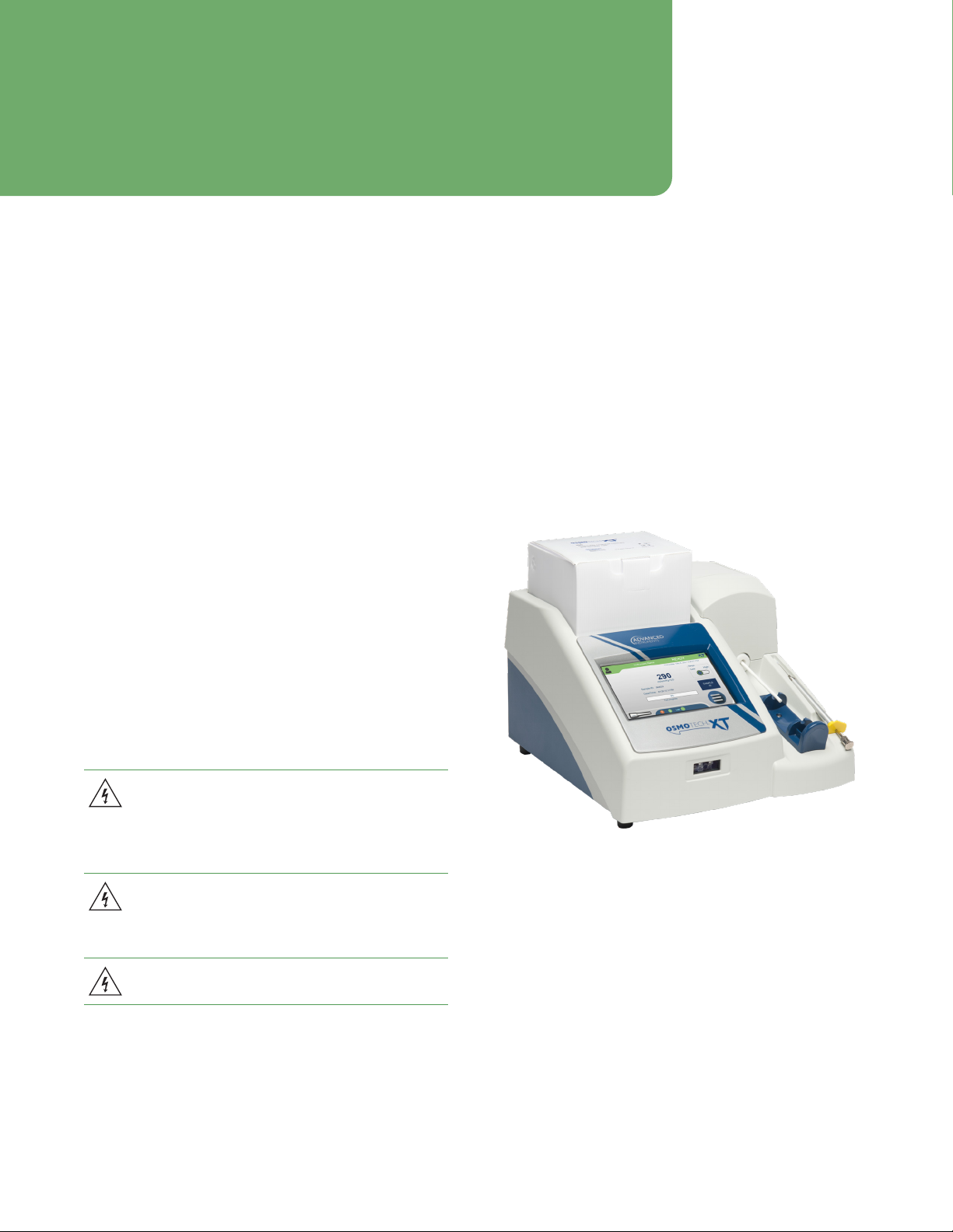
Chapter 1: Overview ....................................................... 11
1.1 Front view ............................................................................................11
1.2 Rear view..............................................................................................11
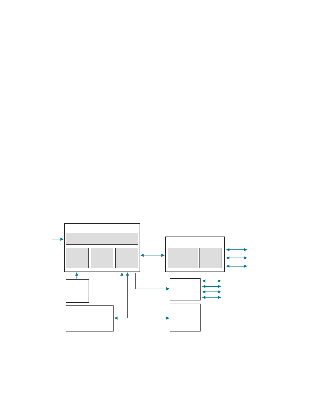
1.3 Mechanical description ...................................................................11
1.4 Electrical description......................................................................12
1.5 Capturing screens to help with troubleshooting.................13
Chapter 2: Setup ............................................................ 14
2.1 Location requirements ...................................................................14
2.2 Placing the Micro-Sample Test Kit on the instrument........14
2.3 Connecting to a network (optional) .........................................15
2.4 Powering up the instrument ........................................................15
Setting the installation date ..................................................... 15
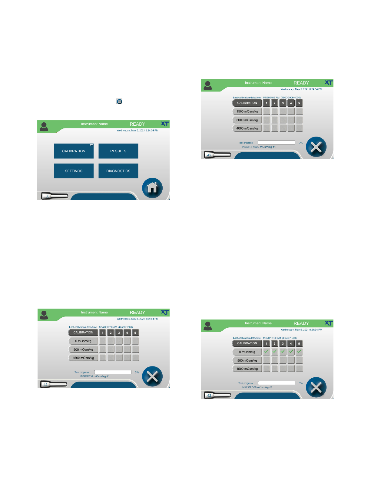
Chapter 3: Calibration................................................... 16
3.1 Factory calibration...........................................................................16
3.2 When to recalibrate.........................................................................16
3.3 Configuring the operating range ...............................................16
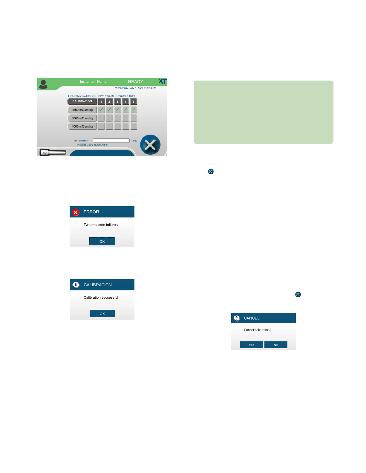
3.4 Calibration procedure.....................................................................17
3.5 Canceling calibration ......................................................................18
Canceling the test in progress.................................................18
Canceling the entire calibration..............................................18
3.6 Calibration errors..............................................................................19
Chapter 4: Diagnostics................................................ 20
4.1 Accessing the Diagnostics menu ..............................................20
4.2 Testing A/D functions....................................................................20
4.3 Checking consumables status.....................................................21
4.4 Testing the sample probe.............................................................22
4.5 Testing the barcode scanner.......................................................22
4.6 Viewing and exporting events....................................................22
Filtering the Events list..............................................................23
4.7 Testing the printer...........................................................................24
4.8 LCD .......................................................................................................24
4.9 Testing the solenoid .......................................................................24
4.10 Logging instrument maintenance and repair.......................24
Logging routine instrument cleaning .................................. 25
Logging preventative maintenance......................................25
Logging repair information .....................................................26
Chapter 5: Configuring settings.................................27
5.1 The Settings screen........................................................................ 27
Default user accounts................................................................ 27
5.2 Setting the date and time............................................................ 27
Synchronizing to a network time server ............................ 27
Entering the date and time manually ..................................28
5.3 Changing the language.................................................................28
5.4 Changing the probe resistance..................................................28
5.5 Setting up networking communications................................29
Configuring a LAN connection...............................................29
Configuring OPC-UA communication ................................ 30
Enabling the web server.......................................................... 30
Viewing and printing data from the webserver...............31
Connecting to a LIS....................................................................32
Send-results mode......................................................................32
5.6 Managing instrument data...........................................................32
Configuring data export ...........................................................32
Exporting data manually ..........................................................33
Backing up the database..........................................................33
Backing up databases manually............................................34
Configuring data recording and clearing database
tables................................................................................................35
Importing/restoring database records................................35
Exporting a single result ..........................................................37
5.7 Assigning user restrictions .......................................................... 37
Changing password settings...................................................38
Configuring testing access ......................................................38
Configuring audits of test results (approvals, reviews,
and comments) ............................................................................39
Setting timeouts ......................................................................... 40
5.8 Updating the system..................................................................... 40
Resetting instrument system settings..................................41
Configuring V&V settings..........................................................41

4
OsmoTECH XT Single-Sample Micro-Osmometer Service Guide
Chapter 6: Maintenance and service........................ 42
6.1 Who should perform service ......................................................42
6.2 Issues that require a service technician..................................42
6.3 ESD precautions ..............................................................................42
6.4 Maintenance ......................................................................................43
Chamber cleaning .......................................................................43
Solenoid maintenance ...............................................................43
Fuse replacement....................................................................... 44
Sampler plunger wire replacement and verification......45
6.5 Service.................................................................................................46
Chapter 7: Troubleshooting ........................................47
7.1 General errors ...................................................................................47
7.2 Errors during calibration...............................................................47
7.3 Errors during testing......................................................................47
7.4 Recovering the Administrator account...................................48
Appendix A: Performance characteristics .............. 49
Appendix B: Product specifications......................... 50
Appendix C: OPC-UA Features and Configuration 51
C.1 OPC-UA overview ............................................................................51
Functional equivalence ..............................................................51
Cross-platform support..............................................................51
Security ............................................................................................51
Information modeling .................................................................51
Appendix D: Known limitations..................................52
Appendix E: Regulatory notices ................................53
Appendix G: System schematic................................. 56
Appendix H: Service log ..............................................57
Appendix I: Replacement parts................................. 59

OsmoTECH XT Single-Sample Micro-Osmometer Service Guide 5
Contacting Advanced Instruments
General inquiries
•US or Canada
•Toll free phone: 800-225-4034 from 8:00 AM – 4:30 PM Eastern time
•Outside the US or Canada:
•Phone: +1 781-320-9000
•Email: info@aicompanies.com
•Web: aicompanies.com
Customer Service/Orders
To order supplies for your OsmoTECH XT, contact the Customer Service department.
•US or Canada
•Toll free phone: 800-225-4034 from 8:00 AM – 4:30 PM Eastern time
•Outside the US or Canada:
•Phone: +1 781-320-9000
•Email: orders@aicompanies.com
Technical Service
For any questions or problems related to operation or service, contact the Technical Service department.
•US or Canada
•Toll free phone: 800-225-4034 from 8:00 AM – 4:30 PM Eastern time;
after normal business hours, follow prompts
•Outside the US or Canada:
•Phone: +1 781-320-9000
•Email: techsupport@aicompanies.com

OsmoTECH XT Single-Sample Micro-Osmometer Service Guide 6
Supplies, standards and controls
To order supplies, standards, and controls, email or call customer service. See Contacting Advanced Instruments.
General supplies
Item Part #
XT100 test kit (1 box of 100 sampler tips
andchamber cleaners, and 1 plunger wire) XT100
Replacement plunger wire 3M0828A
20-μL Ease-Eject™ Sampler 3M0825
OsmoTECH XT User Guide USB drive 235005UG
OsmoTECH XT Service Guide 235006EN
Calibration standards
Item Part
0 mOsm/kg Calibration Standard
(ten 2-mL ampules)
3MA000
500 mOsm/kg Calibration Standard
(ten 5-mL ampules)
3LA051
1500 mOsm/kg Calibration Standard
(ten 5-mL ampules)
3LA151
3000 mOsm/kg Calibration Standard
(ten 5-mL ampules)
3LA301
4000 mOsm/kg Calibration Standard
(ten 2-mL ampules)
3MA400
Reference solutions and controls
Item
Clinitrol™ 290 Reference Solution
(ten 2-mL ampules)
3MA029
Osmolality Linearity Set (5 levels)
(ten 2-mL ampules)
3LA028
Protinol™ Protein-Based Serum Controls
(3levels) (nine 5-mL vials)
3MA028
Other standards
Item Part #
50 mOsm/kg Calibration Standard
(ten 2-mL ampules)
3MA005
100 mOsm/kg Calibration Standard
(ten 5-mL ampules)
3LA011
200 mOsm/kg Calibration Standard
(ten 2-mL ampules)
3MA020
300 mOsm/kg Calibration Standard
(ten 2-mL ampules)
3MA003
400 mOsm/kg Calibration Standard
(ten 2-mL ampules)
3MA040
850 mOsm/kg Calibration Standard
(ten 2-mL ampules)
3MA085
900 mOsm/kg Calibration Standard
(ten 5-mL ampules)
3LA091
1000 mOsm/kg Calibration Standard
(ten 2-mL ampules)
3MA100
1500 mOsm/kg Calibration Standard
(ten 5-mL ampules)
3LA151
2000 mOsm/kg Calibration Standard
(ten 2-mL ampules)
3MA200
Accessories
Item Part #
Compatible dot matrix printer and cable 135022
Printer paper AN2TP5

OsmoTECH XT Single-Sample Micro-Osmometer Service Guide 7
Safe use
WARNING: To reduce the risk of bodily injury, electric shock, fire, and damage to your instrument, please read and
observe all precautions in this User Guide.
Only operate this product in accordance with the equipment design, operating instructions, and manufacturer
recommendations; to do otherwise may impair the instrument function or create a safety hazard.
Do not attempt to perform electrical work if you are not fully qualified. This manual is not a substitute for electrical
training.
General cautions
•Only power this instrument with the source specified
on the product electrical ratings label. Refer to the
installation instructions.
•If the power cord provided is replaced for any reason
or if an alternate cord is used, the cord must be
approved for use in the local country. The power cord
must be approved for the product listed operating
voltage and be rated at least 20% greater than the
volt-ampere (VA) ratings marked on the product’s
electrical ratings label. The cord end that connects to
the product must have an IEC 60320 connector.
•Plug the product into an approved grounded electrical
outlet. Exposure to AC voltage could lead to electric
shock, burn or electrocution. Please be aware of any
exposure of AC voltage in the power cord.
•Do not disable the power cord grounding pin.
•If an extension cord or power strip is used, make sure
that the cord or strip is rated for the product, and that
the total ampere ratings of all products plugged into
the extension cord or strip do not exceed 80% of the
cord or strip rating limit.
•Route power cords so that they will not be walked on,
tripped on, or pinched by items placed upon or
against them. Pay particular attention to the plug,
electrical outlet, and the point where the cord exits the
product.
•Do not pull on cords and cables; grasp the
corresponding connector to unplug it.
•Do not install or use this product in any area subject to
extreme short-term temperature variations, or
locations that exceed the specified operating
environment temperatures.
•Never use this product in a wet area.
•To avoid injury or fire hazard, do not operate this
product in an explosive atmosphere.
•Do not install or use the product on an unstable,
non-level work surface.
•Do not operate this product with the covers removed
or unsecured.

Safe use
8
OsmoTECH XT Single-Sample Micro-Osmometer Service Guide
Symbol conventions
The list of symbols below is for reference only. Some symbols shown below might not appear on the instrument or in the
accompanying documentation.
Symbol Description
!
This symbol alerts the user to the presence of important operating and maintenance (servicing) instructions.
This symbol alerts the user to the presence of uninsulated dangerous voltage inside the enclosure that may
constitute risk of electric shock to persons.
This symbol alerts the user to the presence of internal components that could be damaged by static electricity.
This symbol alerts users to the presence of biological substances that may pose a threat to the health of living
organisms, primarily that of humans.
This symbol indicates potential puncture hazards; users keep hands clear.
This symbol alerts the user to the presence of a specific component that could be damaged by static electricity.
This symbol indicates the presence of alternating current (AC).
This symbol indicates the presence of a fuse.
This symbol indicates the presence of protective earth ground.
This symbol indicates the power is ON.
This symbol indicates the power is OFF.
Read the manual.
Keep dry.
Do not reuse.
Sucient for 100 uses.
LOT Lot number.
Manufactured by.

Safe use
9
OsmoTECH XT Single-Sample Micro-Osmometer Service Guide
FCC Statement
WARNING: Changes or modifications to this unit not
expressly approved by the party responsible for
compliance could void the user’s authority to operate the
equipment.
This equipment has been tested and found to comply
with the limits for a Class A digital device, pursuant to
Part 15 of the FCC Rules. These limits are designed to
provide reasonable protection against harmful
interference when the equipment is operated in a
commercial environment. This equipment generates,
uses, and can radiate radio frequency energy and, if not
installed and used in accordance with the instruction
manual, may cause harmful interference to radio
communications. Operation of this equipment in a
residential area is likely to cause harmful interference in
which case the user will be required to correct the
interference at his own expense.
Industry Canada Statement
CAUTION: Any changes or modifications not expressly
approved by the party responsible for compliance could
void the user’s authority to operate the equipment.
ATTENTION: Tout changement ou modification non
expressément approuvé par la partie responsable de la
conformité pourrait annuler l’autorisation de l’utilisateur
d’utiliser l’équipement.
This device complies with Industry Canada license-
exempt RSS standard(s). Operation is subject to the
following two conditions: (1) This device may not cause
interference, and (2) this device must accept any
interference, including interference that may cause
undesired operation of the device.
Le présent appareil est conforme aux CNR d’Industrie
Canada applicables aux appareils radio exempts de
licence. L’exploitation est autorisée aux deux conditions
suivantes: (1) l’appareil ne doit pas produire de
brouillage, et (2) l’utilisateur de l’appareil doit accepter
tout brouillage radioélectrique subi, même si le
brouillage est susceptible d’en compromettre le
fonctionnement.
BIOHAZARDOUS MATERIAL CAUTION
WARNING: Handle all biohazardous materials according
to established good laboratory practices and follow
your institution exposure control plan. Persons handling
blood and body fluid samples must be trained in
blood-borne hazards and should observe Universal
Precautions for Preventing Transmission of Bloodborne
Infections as defined by the Centers for Disease Control
and Prevention (CDC). The Universal Precautions
guideline provides infection control by treating all
blood and body fluids as if known to be infectious. Use
personal protective equipment such as gloves, gowns,
etc., to prevent exposure. Store biohazardous materials
in regulated waste containers and dispose of these
materials in a safe and acceptable manner that is in
compliance with all country, state and local
requirements.
If a biohazardous material is spilled on or inside the
equipment, decontaminate the equipment using a 1%
bleach solution, or as outlined by those policies and
procedures established within your institution.
To avoid injury or fire hazard, do not operate this
product in an explosive atmosphere.
Use caution and appropriate personal protective
equipment (PPE) if you must put your hands inside the
osmometer. Placing hands into the opening could result
in skin punctures or other injuries.

OsmoTECH XT Single-Sample Micro-Osmometer Service Guide 10
Foreword
Intended use
Advanced Instruments osmometers use the technique of
freezing point depression to measure osmolality.
Osmolality is the total solute concentration of an
aqueous solution. Osmometers measure the number of
solute particles irrespective of molecular weight or ionic
charge.
Osmolality information is useful to the following
disciplines:
• Medical research
• Biotechnology and pharmaceutical research and
manufacturing
• Academic research
• Industrial applications
NOTE: OsmoTECH XT is not for patient diagnostic use.
Osmolality is a valuable in-process test that provides a
reliable and repeatable value that reflects overall solute
content of a solution. Osmolality is a critical indicator
used throughout the bioproduction process to assure the
highest quality and yield of biologics. It should be a
routine and frequent check to prevent costly loss of
product or suboptimal production and to ensure the
process is within specification.
About this Service Guide
This Service Guide contains:
• Instructions for performing repairs
• Guides for troubleshooting operational and
mechanical problems
• Circuit system illustrations
• Information about replacement parts and service
repairs
This guide is designed to assist service technicians and
does not imply a license to perform repairs without
proper qualifications.

OsmoTECH XT Single-Sample Micro-Osmometer Service Guide 11
Chapter 1: Overview
This chapter provides a general description of the
OsmoTECH XT components and its mechanical and
electrical operation.
1.1 Front view
The front view of the OsmoTECH XT is shown below:
Cooling chamber
(inside)
Sampler
Sampler tips
Operating cradle
Barcode scanner
Micro-Sample Test Kit
Chamber cleaners
Touchscreen
Sampler holder
These major components are identified in the image:
• Sampler
• Sampler holder (a convenient resting place for the
sampler when it is not in use)
• Operating cradle
• Cooling chamber (inside)
• Touchscreen
• Barcode scanner
• Micro-Sample Test Kit (contains 100 chamber cleaners,
100 sampler tips, and one plunger wire)
1.2 Rear view
The rear view of the OsmoTECH XT is shown below:
Power switch
USB 2.0
Type B port
Ethernet port Plug for power
cord
USB 2.0
Type A ports
Exhaust fan
1.3 Mechanical description
Mechanically, the OsmoTECH XT contains the four major
components shown in the diagram and listed below.
Thermal Printer
(optional)
Power Supply and
Controls Assembly
Osmometer Module
Display Assembly
110–2
40 VAC
50/60 Hz
• Sample Handling Assembly: Testing is performed in
this osmometer module. The sample handling
assembly monitors and controls the sample probe,
cooling assembly, and actuator switch.
• Power Supply and Control Assembly: This component
provides power to the instrument via the fused power
inlet assembly. The control PCB contains the logic to
perform osmometer tests and manage
communications with the display assembly and
barcode scanner. The USB and Ethernet ports are
mounted to the power supply and controls assembly,
and are connected to the display assembly.
• Display Assembly: This assembly consists of the
display PCB and the touchscreen display. It provides
the graphical user interface (GUI) used to show and
retrieve information about tests and the instrument
configuration. The USB and Ethernet port interfaces
and cables are part of the display assembly.

Chapter 1 Overview
OsmoTECH XT Single-Sample Micro-Osmometer Service Guide 12
1.4 Electrical description
This section describes the major electrical components
in the OsmoTECH XT (see Mechanical description).
Power supply and control PCB assembly (p/n 235028)
The power supply and control PCB assembly is divided
into lower and upper sections using a metal shelf.
• The lower section contains the power entry module
(PEM), a 200W AC/DC power supply, and a fan. All
high-voltage connections are contained in the lower
section, making it safe to operate the instrument with
either the rear door and/or cover removed.
• The upper section contains the control PCB
(p/n235027PC). This board controls all of the
instrument’s low-level, time-sensitive operations, such
as the thermo-electric chamber, solenoid, barcode
scanner, and high-precision temperature probes. The
control board uses the PIC32MZ microchip
micro-controller.
Barcode scanner port
This port communicates to a 2D barcode scanner
(Diamond Technologies DSE0450-DTC0E) via 115Kbps,
1start bit, 1 stop bit, and no parity protocol. The
scanner’s presentation mode activates when an object
trips the scanner’s proximity sensor. The sensor has
built-in red illumination LEDs to help read barcodes in
low light conditions.
RS-232 driver circuits
The instrument uses three RS-232 ports:
• Communication to display PCB
• Communication to scanner
• Communication to printer
A transceiver IC handles the level translation of all three
ports.
Sample cooling assembly circuits
The sample cooling assembly circuit PCB controls the
following:
• TEC cooling block
• Two fans used to exhaust air from the power box and
remove heat from the TEC module
• Activation of the solenoid for sample nucleation
• A/D readings of the Wheatstone bridge circuits of the
sample probe and block probe
Display assembly (p/n 235022)
The display assembly functions as the main user
interface controller and provides connectivity to the USB
and Ethernet peripherals. It contains the display PCB and
color LCD screen, resistive touch element, and the USB/
Ethernet extension cables. The assembly is secured
underneath the top of the instrument’s bezel cover.
7" Color/touch LCD screen
The OsmoTECH XT instrument has a 7" WVGA
(800 x 480) LCD/touch screen built into the display
assembly. It uses a metal gasket to reduce radiated
electrical emissions. The LCD screen has a built-in
four-wire resistive touch screen overlay.
Display PCB
The display PCB contains a high-power IMX6 micro-
processor running a real-time operating system (RTOS)
from Mentor Graphics called “Nucleus.” It is used to
interact with the color/touch LCD screen and to provide
the following serial interfaces to the control PCB:
• Two USB 2.0 Type A ports
• One Ethernet port
• One USB 2.0 Type B port

Chapter 1 Overview
OsmoTECH XT Single-Sample Micro-Osmometer Service Guide 13
Interfaces
The display PCB has the following interfaces:
• RS-232 (1x): This serial interface communicates
commands and data to/from the control PCB.
• USB 2.0 Type A (2x): These interfaces allow a USB
device to be attached to the rear of the instrument via
internal shielded USB cables to USB adapter.
• USB 2.0 Type B (1x): This interface allows a USB device
to be attached to the rear of the instrument via
internal shielded USB cable to USB adapter.
• Ethernet (1x): This interface allows a 10/100 RJ45
cable to attach to the rear of the instrument via
internal shielded Ethernet cable to Ethernet adapter.
Non-volatile memory
The display PCB has non-volatile memory used to store
the last one thousand sample records.
The control PCB has non-volatile memory used to store
instrument set-up, calibration, and other pertinent data.
Real-time clock
The display PCB has a real-time clock and a back-up
battery to maintain the date, time, and firmware versions.
The instrument uses three proximity sensors to
determine the presence of sample tubes, objects near
the barcode scanner, thermoelectric module cooling,
activation of the solenoid, and the A/D reading of the
Wheatstone bridge circuits of the sample probe and
block probe.
Cradle switch assembly
The cradle switch is part of the sample handling
assembly. It informs the processor whether the cradle is
fully inserted or is pulled back.
RFID assembly
The RFID assembly reads and updates the count of
sample tips in the test kit box (part no. TECH250) and
allows test to begin when count is greater than zero.
110V
/220V
Power In
Serial 3 – USB A Ports
2 – Temperature Probes (2
4-bit)
1 – TEC Cooler
1 – Solenoid Impactor
1 – Cooling Fan
1 – USB B Port
1 – Ethernet Port
AC/DC
Power
Supply
Exhaust
Fan
Control
PCB
Power Entry Module
(Switch, Fused, Filtered)
Power/Control Box
Color/Touch
Display
Display
PCB
Display Box
Cradle
Switch
Assembly
Sample
Cooling
Assembly
RFID Assembly
Barcode
Scanner
1.5 Capturing screens to help with
troubleshooting.
Any instrument operator can capture the currently
displayed screen on the OsmoTECH XT to a USB drive.
This can be useful for a remote customer to capture
screens and send to a service technician to help
troubleshoot a system issue.
1. Insert a USB drive in one the instruments’ USB ports.
2. Press-and-hold on the top-right corner of the screen
until you hear a click sound to capture and save the
screen images to USB as a PNG file.

OsmoTECH XT Single-Sample Micro-Osmometer Service Guide 14
Chapter 2: Setup
This chapter describes how to set up the OsmoTECH XT
instrument in the laboratory.
2.1 Location requirements
The location of the OsmoTECH XT must meet the
following space and electrical requirements.
OsmoTECH XT dimensions
• Not including Micro-Sample Test Kit:
15" D x 14" W x 10" H
(38 cm D x 36 cm W x 25 cm H)
• Including Micro-Sample Test Kit:
15" D x 14" W x 15" H
(38 cm D x 36 cm W x 38 cm H)
Recommended clearance
Allow 6 inches (15 cm) of clear space on each side of the
instrument.
Do not block the exhaust fan airflow on the back panel
or underneath the instrument.
Electrical requirements
Your instrument must be located within five
feet of a properly grounded, three-prong
electrical outlet capable of continuously
supplying 0.5 amperes at 100–240 VAC
(50–60Hz).
If the instrument is not grounded properly, its
operation may be impaired and a safety hazard
may exist. Verify that the outlet is appropriate
before operating the instrument.
Do not disable the grounding plug.
2.2 Placing the Micro-Sample Test Kit on the
instrument
The XT100 test kit contains a supply of consumables
required for testing: 100 chamber cleaners, 100 sampler
tips, and one plunger wire.
A Micro-Sample Test Kit must be in place on the top left
of the instrument before testing can begin.
NOTE: If a Micro-Sample Test Kit is not in place on the
instrument when you attempt to run a test, you
receive the error, AI consumable box not detected.

Chapter 2 Setup
OsmoTECH XT Single-Sample Micro-Osmometer Service Guide 15
2.3 Connecting to a network (optional)
To connect the OsmoTECH XT to a laboratory
information system (LIS) and/or to a local area network
(LAN), plug an Ethernet cable that connects to the
network into the Ethernet port on the back of the
OsmoTECH XT unit (see Rear view).
NOTE: You must also configure the communication
settings in the OsmoTECH XT software. For more
information, see Setting up networking
communications.
2.4 Powering up the instrument
1. Connect the power cord to the back of the
instrument and insert the plug into the power outlet.
2. Power on the instrument using the rocker switch on
the back by pressing the side marked with the
symbol
When the unit powers up, the Welcome screen appears.
3. After a few moments, the OsmoTECH XT Home
screen appears.
From the Home screen, you can initiate sample
testing and view the results. Initially, the instrument
shows a status of Ready.
4. If one of the following messages appears after
starting up, follow the associated instructions:
• Preventative Maintenance Required - Perform any
scheduled maintenance and record it on the
DIAGNOSTICS>MAINTENANCE screen (see
Logging preventative maintenance).
• Installation date not set. Refer to the User Guide -
Follow the instructions in the next section (Setting
the installation date).
Setting the installation date
If the installation date of the instrument has not been
entered into the system, an Installation date not set.
Refer to the User Guide message appears the first time
an instrument powers up. If the installation date is not
set, this message reappears every hour.
Complete the following steps to enter the installation
date to disable this message and enable the preventative
maintenance reminders based on this date.
1. Press >DIAGNOSTICS>MAINTENANCE and log in.
2. Press the INSTALLATION tab.
3. Press the Installation Date field, select a date
(required) from the calendar, and press OK.
4. Press EDIT (optional - up to 1024 characters) to add
information regarding the installation date.
5. Press Save.
6. Press Exit to return to the Diagnostics menu.
NOTE: After saving the installation date, the date can only
be changed using the Service account.

OsmoTECH XT Single-Sample Micro-Osmometer Service Guide 16
Chapter 3: Calibration
IMPORTANT: Calibrate the OsmoTECH XT only with
Advanced Instruments Calibration Standards.
Using calibration standards that are not manufactured
by Advanced Instruments may yield inaccurate results
and is not recommended.
3.1 Factory calibration
Your OsmoTECH XT was factory-calibrated before it
shipped using five samples of each calibration standard
in the low range (0, 500, and 1500 mOsm/kg HO) and
in the high range (1500, 3000 and 4000 mOsm/kg HO).
The factory calibration is stored within its memory.
Therefore, you do not need to calibrate the instrument
upon installation.
3.2 When to recalibrate
Advanced Instruments recommends that you recalibrate
the OsmoTECH XT in any of the following cases:
• If the test results for the reference solutions are out of
specification
NOTE: Advanced Instruments recommends that you
test appropriate reference solutions daily to
verify the calibration. For more information,
see the Daily procedure section of the
OsmoTECH XT User’s Guide (p/n 235005UG).
• If the instrument has been serviced (especially if any
instrument hardware was replaced)
• If the ambient temperature has changed more than
5°C since the last calibration
• In any other circumstances where calibration is
recommended or required based on the regulations
that govern your laboratory
3.3 Configuring the operating range
The OsmoTECH XT has a built-in calibration function
that by default guides you through testing five samples
each of three calibration standards.
Authorized users can select the operating range used to
calibrate the instrument from the Home screen.
NOTE: The selected range determines both the
calibration sequence and the operating range used
to test samples.
• Select Low to calibrate the
instrument using 0, 500, and
1500mOsm/kg H2O calibration
standards.
• Select High to calibrate the
instrument using 1500, 3000, and
4000 mOsm/kg H2O calibration
standards.

Chapter 3 Calibration
OsmoTECH XT Single-Sample Micro-Osmometer Service Guide 17
3.4 Calibration procedure
To perform a calibration:
1. From the Home screen, press
The Main menu displays.
2. Press CALIBRATION.
The system prompts you to log in.
3. Select yourself from the list of available users.
4. Enter your password and press Enter to open the
Calibration screen.
The following Calibration screens show instruments
configured for low range calibration (0, 500, and
1500 mOsm/kg H2O) and an instrument configured
for high range calibration (1500, 3000, and
4000mOsm/kg H2O)
Instrument configured for low range
calibration (0, 500, and 1500 mOsm/kg H2O)
Instrument configured for high range calibration
(1500, 3000, and 4000 mOsm/kg H2O)
5. Follow the onscreen instructions to test samples
from each specified standard five times.
NOTE: Test samples of known standards depending
on the configured operating range:
•Low range calibration
(0, 500, and 1500 mOsm/kg HO)
•HIGH range calibration
(1500, 3000, and 4000 mOsm/kg HO)
NOTE: Use the method for sample testing explained
in the Testing procedure section of the
OsmoTECH XT User’s Guide
(p/n 235005UG).
•After each successful calibration test, a green
checkmark appears in the calibration matrix and
the instrument prints DONE for that calibration
test.

Chapter 3 Calibration
OsmoTECH XT Single-Sample Micro-Osmometer Service Guide 18
• If a single calibration test fails or is canceled, the
system prompts for a retest using a new sample.
• If two failures occur within the same standard
group, that calibration fails and the screen displays
the message Two replicate failures.
• Upon completion of the last calibration test, the
system displays a Calibration successful message
or the reason for failure.
6. Click OK to close the success (or failure) message.
• When you close a success message, the system
returns you to the Home screen.
• When you close a failure message, the system
clears all checkmarks and returns you to the
Calibration screen. From there, you can restart the
calibration or exit to the Home screen.
When calibration is successful, the instrument calculates
a new calibration slope and intercept and saves those
values to memory.
If a calibration test fails or is canceled for any reason,
the instrument does not save that calibration data;
instead, it maintains the last successful calibration.
The date of the last successful calibration is displayed
on the Calibration screen.
3.5 Canceling calibration
Press at any time to cancel a calibration test in
progress or the entire calibration process.
Canceling the test in progress
To cancel the particular test in progress, retract the
sample handler cradle. The system prompts you to retest
with a new sample.
NOTE: You can cancel individual tests as often as
necessary. Cancellation of an individual test does
not count toward the limit of two failures within a
calibration set.
Canceling the entire calibration
If you cancel the entire calibration, the instrument
maintains the last successful calibration.
1. To cancel the entire calibration, press .
A confirmation prompt appears.
2. At the confirmation prompt, press Yes to confirm
cancellation, or No to continue calibration.
If you press Yes to confirm cancellation, the system
discards any data from this calibration and returns
you to the Home screen.

Chapter 3 Calibration
OsmoTECH XT Single-Sample Micro-Osmometer Service Guide 19
3.6 Calibration errors
The following table lists errors that can occur during
calibration.
Error Possible cause/Suggested action
Calibration failed Action: Repeat calibration.
Calibration
required
Cause: A significant maintenance event
has occurred (for example, the probe
resistance has been changed).
Action: Recalibrate the instrument.
Calibrator out of
range:
0 mOsm/kg,
500 mOsm/kg,
1500 mOsm/kg,
3000 mOsm/kg,
or 4000 mOsm/kg
Cause: Too much variation in the
replicates for the calibrator group.
Action:
• Confirm good technique.
• Confirm sample handler is in good
condition.
• Check for particulates in sample.
Out of range: Low
Out of range: High
Cause: The result for the calibrator is
below/above the expected range for
that calibrator group.
Action: Make sure you are using the
correct calibrator.
Sample did not
freeze
See Troubleshooting.
Sample pre-freeze See Troubleshooting.
Test timeout See Troubleshooting.
Two replicate
failures
Cause: Two individual test failures
occurred within the same calibrator
group.
Action: Repeat calibration.
Wrong calibrator:
0 mOsm/kg,
500 mOsm/kg,
1500 mOsm/kg,
3000 mOsm/kg,
or 4000 mOsm/kg
Cause: The result for the calibrator was
above or below the expected range for
that calibrator group two times.
Action: Make sure you are using the
correct calibrator.

OsmoTECH XT Single-Sample Micro-Osmometer Service Guide 20
Chapter 4: Diagnostics
This chapter describes basic diagnostic procedures to
perform on the OsmoTECH XT.
4.1 Accessing the Diagnostics menu
The Diagnostics menu provides access to the functions
listed in the following table.
Function Description/Use
A/D Analog to digital circuit testing
Consumables Test kit reader test
Sample Probe Measure the sample probe resistance
Barcode Test the barcode scanner
Events View/export system events log
Printer Test the printer
LCD Inspect screen for dead pixels
Solenoid Executes multiple impacts
Maintenance Log routine cleaning, preventative
maintenance, and repairs of instrument, and
save to instrument events database
To access the Diagnostics menu:
1. Press on the Home screen to open the Main
menu.
2. Press Diagnostics from the Main menu to open the
Diagnostics menu.
From the Diagnostics menu, you can press a button to
select a function, (described in the following sections),
or you can press the Home button to return to the Home
screen.
4.2 Testing A/D functions
The A/D function tests the performance of the analog to
digital converter (A/D), sample probe, block probe,
cooling assembly, and the eciency of heat transfer
between the components of the cooling assembly.
Results are presented as resistance (ohms), temperature
(°C), and power level %.
1. Press DIAGNOSTICS > A/D to open the A/D screen.
2. Press a set point temperature from the drop-down
menu at the top of the screen.
Testing begins.
Other manuals for OsmoTECH XT
1
Table of contents
Other Advanced Instruments Medical Equipment manuals

Advanced Instruments
Advanced Instruments OsmoPRO Multi-Sample User manual

Advanced Instruments
Advanced Instruments Osmo1 User manual

Advanced Instruments
Advanced Instruments OsmoTECH PRO User manual

Advanced Instruments
Advanced Instruments OsmoTECH XT User manual

Advanced Instruments
Advanced Instruments 3250 User manual

Advanced Instruments
Advanced Instruments Osmo1 User manual

Advanced Instruments
Advanced Instruments Anoxomat III User manual

Advanced Instruments
Advanced Instruments OsmoTECH User manual

Advanced Instruments
Advanced Instruments Anoxomat Mark II CTS User manual

Advanced Instruments
Advanced Instruments 3900 User manual