DARAY X740 Manual

X740
LED Examination Light
Operating & Installation Manual
QAM.X740.0519.4

Page 1of 30

Page 2of 30
Table of Contents
1. Introduction ........................................................................... 3
1.1 Supported Lights ................................................................. 4
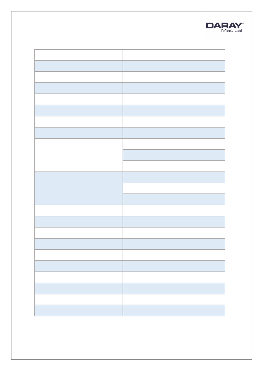
2. Technical Specifications ............................................................ 5
2.1 Pre-Installation Responsibilities and component packing list ........... 6
2.2 Pre-Start Checks ................................................................. 7
3. Operation .............................................................................. 8
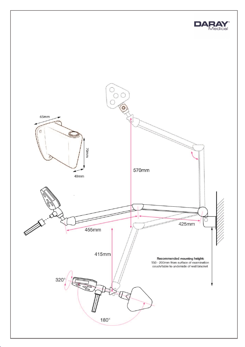
3.1 Range of Motion.................................................................. 8
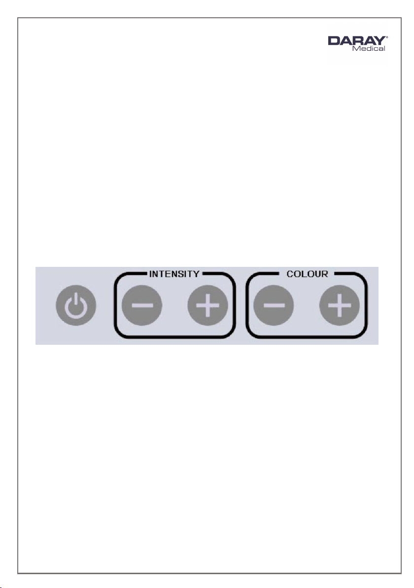
3.2 Powering On & Variable Intensity ............................................ 9
3.3 Adjusting the Light Head ...................................................... 10
4. Installation ........................................................................... 11
4.1 Wall mounted versions........................................................ 11
4.1.1 Considerations ............................................................ 12
4.1.2 X740LW - Placement and Installation................................. 13
4.1.3 X740LE1 –Placement and Installation ................................ 15
4.1.4 X740LE2 –Placement and Installation ................................ 15
4.1.5 X740LE3 –Placement and Installation ................................ 16
4.1.6 X740LE4 - Placement and Installation ................................ 16
4.2 Rail mounted version (X740LR) .............................................. 18
4.3 Desk mounted versions (X740LD / X740LDS / X740LFDM) .............. 18
4.4 Mobile version (X740LM) ...................................................... 19
4.5 Optional battery back-up..................................................... 21
4.5.1 Packing List ................................................................ 21
4.5.2 Install........................................................................ 21
5. Maintenance ......................................................................... 22
5.1 Maintenance schedule ......................................................... 22
5.2 Safety Precautions.............................................................. 22
5.3 Product cleaning & care guidelines ......................................... 23
5.4 Head Adjustment ............................................................... 24
5.5 Detaching Parts ................................................................. 24
5.6 Rigid Arm Adjustments ........................................................ 25
6. Troubleshooting Guide & Spare Parts ........................................... 26
7. Warranty Information .............................................................. 28
7.1 Returns Policy ................................................................... 28
7.2 Warranty Details ................................................................ 29

Page 3of 30
1. Introduction
DARAY’s X740 is a state-of-the art, cost-effective examination light for use during
medical or veterinary consultation and diagnosis. The light uses the latest LED
technology to give an intense light at the ideal colour temperature for accurate
medical diagnosis (without the need for secondary filtering) with virtually no heat.
Multiple mounting options are available.
The X740 features a high-output intensity and variable colour temperature, which is
variable via a touch panel on the side of the light head. The light operates from a
safe low voltage produced by a mains transformer, and has a swivelling, spring-
balanced arm system and a rotating head to allow accurate and stable positioning of
the light-patch.
The light comprises 3 parts: light-head and articulated arm system, power-supply
module, and the mount of choice. The rigid spring-balanced arm allows the light-
patch to be placed accurately and stably where it is needed.
All versions are delivered in special-to-type packaging which identifies on the ends of
the box the model type and serial number of the light within.
This user & installation guide contains all the information you need for installation,
operation and maintenance.
Restrictions and Liabilities
Information in this document is subject to change and does not represent a
commitment by DARAY. Changes made to the information in this document will be
incorporated in new editions of the publication. No responsibility is assumed by
DARAY for the use or reliability of software or equipment that is not supplied by
DARAY.

Page 4of 30
For further information on our product range and find out more about our Company
please visit www.daray.co.uk or call 0333 321 0971.
This product was designed & manufactured in Great Britain by:
Daray Ltd.
Edison House
Robian Way
Swadlincote
Derbyshire
DE11 9DH
1.1 Supported Lights
The Following Models are supported in this Manual
X740LW
X740 LED Wall Mounted Light
X740LR
X740 LED Rail Mounted Light
X740LD
X740 LED Desk Mounted Light
X740LDS
X740 LED Weighted Desk Stand Light
X740LDFM
X740 LED Fixed Desk Mount Light
X740LM
X740 LED Mobile Weighted Base Light
X740LE1
X740 LED Hardwired W3 BESA Wall Mounted Light
X740LE2
X740 LED Hardwired W4 Spreader Plate Wall Mounted Light
X740LE3
X740 LED Hardwired W5 Panel Mounted Light
X740LE4
X740 LED Hardwired W6 Wall Mounted w/ Integral PSU

Page 5of 30
2. Technical Specifications
Light Source
LED
Light Intensity (Lux) @ 0.5m
80,000 Lux ±5%
Light Intensity (Lux) @ 0.75m
40,000 Lux ±5%
Light Intensity (Lux) @ 1.0m
20,000 Lux ±5%
Light Intensity Adjustment Range
25% - 100%
Colour Temperature (Kelvin)
3,600 –5,000K ±500
Colour Rendering Index (CRI)
95
Colour Rendering (R9)
95
Light Field Diameter (D50)
@ 0.5m: 60mm
@ 0.75m: 90mm
@ 1.0m: 120mm
Light Field Diameter (D10)
@ 0.5m: 110mm
@ 0.75m: 150mm
@ 1.0m: 200mm
Number of LED’s
4
Power Consumption
16W 0.14A
Average Working Life
>40,000 Hours
Input Voltage
100 - 240V AC 50/60 Hz
Output Voltage
12V DC 2A
Temperature Rise on Patient/User
≤2°C
Warranty Period
5 Years
NHS E-Class Code
FBU, FKR
Commodity Code
9018 908400
GMDN Code
12276

Page 6of 30
2.1 Pre-Installation Responsibilities and component packing list
This document is a guide to the steps that need to be performed to correctly install
the X740 Examination light. However, the work required to be performed is the
responsibility of the owner or designated contractor/s.
All fixings between DARAY lights and the building super-structure must be approved
by either the chief project engineer or an appropriate and competent structural
assessor.
The components supplied by DARAY for fitting / installation should be the following
items in the specified quantities.
X740LD/FDM/S
Qty.
X740LW
Qty.
12V Plug top transformer (1.8m)
1
12V Plug top transformer (1.8m)
1
Desk Clamp/Fixed Desk Mount/Desk
Stand
1
Wall bracket + fixings
1
Light head and rigid arm system
1
Thumb Screw for Wall Mount
1
Microfibre cloth
1
Light head and rigid arm system
1
User Manual
1
Microfibre cloth
1
User Manual
1
X740LR
Qty.
X740LM
Qty.
12V Plug top transformer (1.8m)
1
IEC Cable (3m)
1
Rail Clamp
1
12V PSU + bracket kit
1
Thumb Screw for Rail Clamp
1
Mobile base (3 pieces)
1
Light head and rigid arm system
1
Light head and rigid arm system
1
Microfibre cloth
1
Microfibre cloth
1
User Manual
1
User Manual
1
X740LE1
Qty.
X740LE2
Qty.
12V Transformer
1
12V Transformer
1
BESA Wall Bracket (W3)
1
Spreader Plate Wall Bracket (W4)
1
Light head and rigid arm system
1
Light head and rigid arm system
1
Microfibre cloth
1
Microfibre cloth
1
User Manual
1
User Manual
1

Page 7of 30
X740LE3
Qty.
X740LE4
12V Plug top transformer
1
Light head and spring rigid arm
system incl. base box (transformer
integrated)
Panel Mount Bracket (W5)
1
Microfibre cloth
Light head and rigid arm system
1
User Manual
Microfibre cloth
1
User Manual
1
2.2 Pre-Start Checks
Please check that the power cable is without visible damage, harsh folds, knots or
cuts in the rubberised coating.
When applicable, please check that the cable is fully inserted into the power socket,
before switching the power on.
Please check that the head and all parts of the base are without visible damage.

Page 8of 30
3. Operation
3.1 Range of Motion
The full range of motion between the X740 Range varies.
This is an image depicting the range of motion on a standard wall mount fitting.

Page 9of 30
3.2 Powering On & Variable Intensity
The X740 uses a control panel on the side of the light-head to power the light on and
off, and to adjust the brightness (intensity), and colour temperature.
-Press the power button to power ON or OFF.
-Press and hold the plus or minus buttons to adjust the intensity. It takes
approximately 5 seconds to switch between the highest and lowest
settings. Release the button when at a comfortable setting for the user.
-You can also press the plus and minus buttons to fine tune the intensity.
-Repeat the above steps to adjust the colour temperature.

Page 10 of 30
3.3 Adjusting the Light Head
The X740 head is secured using an adjustment knob on the side of the arm, near the
head. This also controls the forward and backward motion of the head itself.
Loosening this thumb screw will allow you to position the light-head up or down.
NOTE: Care should be taken not to over tighten the screw.
Thumb Screw

Page 11 of 30
4. Installation
4.1 Wall mounted versions
Compatible versions: X740LW / X740LE1 / X740LE2 / X740LE3 / X740LE4
The wall bracket needs to be true on the vertical plane.
PIVOTW2: supplied with
X740LW
PIVOTW6: supplied with X740LE4
PIVOTW5: supplied
with X740LE3
PIVOTW4: supplied
with X740LE2
PIVOTW3: supplied
with X740LE1

Page 12 of 30
4.1.1 Considerations
Wall Construction
Before fixing it is important to consider the strength of
the wall and the depth of the fixings used.
Use of a building engineer or structural drawings may be
required to decide on suitability.
Examinations to be
undertaken
We recommend the bracket be installed approximately
850-1100mm from the floor to the underside of the
bracket –dependent on couch height.
It may be necessary to adjust this height, if there are
specific medical procedures the light will be used for. If
in doubt consult the end user or DARAY. When installing
the bracket take consideration of where you want the
light head to sit when in its lowest position.
Locations of nearest
mains sockets
The X740 wall mounted light uses a plug-top transformer
with a DC jack connection.
Only the supplied certified power adapter should be used
with the light.
The length of this cable is approximately 1.8m so the wall
mounted light should be within 1.5m of a mains power
point.
NOTE: The following versions are not supplied with a
plug-top transformer (X740LE1 / X740LE2 / X740LE3 /
X740LE4). A separate transformer is supplied to make a
hardwired connection.

Page 13 of 30
4.1.2 X740LW - Placement and Installation
The power supply for the X740LW is a plug top transformer with a DC jack
connection, these can be inserted into any standard UK wall socket.
Please note, under no circumstances should this product be connected
directly to the Mains electrical supply, this product requires a Low
Voltage Connection only and must only be used with a Daray Certified
Power Adapter.
• Remove the light from its packaging.
• Mark on the wall the selected location for the
wall-mounting bracket, bearing in mind the final
position of the light head required to project its
light-patch where it will be needed.
We recommend 850-1100mm from the floor to
the underside of the bracket –dependent on
couch height. Ideally, the underside of the
bracket should be 150-200mm above the couch.
•Taking note of the considerations in section 4.1.1,
mount the PIVOTW2 wall bracket directly to the
wall. Use a spirit level to ensure the bracket is on a
true vertical plane.
•Once the bracket is installed, turn the
thumbscrew anti-clockwise to allow a clear path
through the hole, and then slide the light spigot
directly into the hole in the bracket. Make sure the
light is fully pushed in.
•Tighten the thumbscrew to secure the light in
position.

Page 14 of 30
The light can now be tested by connecting the DC jacks and applying power. Press
the switch on the head to power your light on. See page 9
Check arm and head for smooth and correct movement. Your new DARAY light is now
ready for use.
To gain full support of our warranty please fill in our warranty web form or
contact DARAY by phone or email.
We also provide service plans to help you maintain your light. Contact
DARAY on 0800 878 9864 for more details.

Page 15 of 30
4.1.3 X740LE1 –Placement and Installation
Remove the light from its packaging.
This version includes our PIVOTW3 BESA mounting bracket, for mounting to a
BESA box.
Ensure the BESA back-box is mounted between recommended 850-
1100mm from the floor to the underside of the bracket –dependent on
couch height. Ideally, the underside of the bracket should be 150-
200mm above the couch.
A separate transformer is supplied.
Run low voltage cable (not supplied) between the BESA, through trunking,
to the transformer location.
Fit light into PIVOTW3 and make electrical connection, observing polarity.
Fix the PIVOTW3 bracket to the BESA box (screws not supplied). Ensure a
secure fit.
Power the transformer and test the light.
4.1.4 X740LE2 –Placement and Installation
Remove the light from its packaging.
This version includes our PIVOTW4 spreader plate wall mounting bracket.
Suitable for fixing to all wall types, including brickwork. A separate power
supply is included.
Mark on the wall the selected location for the wall mounting bracket,
bearing in mind the final position of the light head required to project its
light patch where it will be needed.
We recommend 850-1100mm from the floor to the underside of the
bracket –dependent on couch height. Ideally, the underside of the
bracket should be 150-200mm above the couch.
Taking note of the considerations in section 4.1.1, mount the PIVOTW4 wall
bracket directly to the wall. Use a spirit level to ensure the bracket is on a
true vertical plane.
Once the bracket is installed, turn the thumbscrew anti-clockwise to allow a
clear path through the hole.
Slide the light spigot directly into the hole in the bracket. First, make sure
to thread the cable through the Make sure the light is fully pushed in.
Tighten the thumbscrew to secure the light in position.

Page 16 of 30
4.1.5 X740LE3 –Placement and Installation
Remove the light from its packaging.
This version includes our PIVOTW5 panel
mounting bracket.
Fit front bracket and rear plate to pre-drilled
panel.
Fit light spigot into bracket and pass cable
through to the rear of panel.
Make electrical connection to transformer.
Fit pre-drilled panel to panel mount.
Apply power and test light.
4.1.6 X740LE4 - Placement and Installation
Backing plate dimensions
and fixing points

Page 17 of 30
Terminal block
Non-slip washer
Nut
CAUTION: This product must be earthed.
Check you have all of the items included in the checklist on Page 7
Note the mounting position advice and warnings offered in Section 4.1.1 Considerations on
page 10
Flush-fitting the wall box (chased-in cables):
Remove the 4 cover screws from the wall mounting box with the hex wrench provided
Feed the mains supply via the cable entry hole on the back plate
Connect the mains supply to the fused terminal block found on the back plate
Using the back-plate as a template, mark its position on the wall, bearing in mind
the final position of the light-head. Fixing point dimensions on page 16 of this manual
Fix the bracket to the wall
Fit the power supply module to the wall bracket with the 4 cover screws
Switch the power on and check for correct operation

Page 18 of 30
4.2 Rail mounted version (X740LR)
Remove the light from its packaging.
If you have also purchased our XRAIL accessory, hold the rail against the
selected location on the wall, bearing in mind the final position and range of
travel of the light-head required to project its light patch where it will be
needed.
Ensuring the rail is horizontal; mark the positions for the 2 screw holes.
Fix the rail to the wall, using appropriate plugs as necessary and the 2 screws
provided.
NOTE: Slide the screw-head cap retainers the correct way up onto the screws
before fitting the screws!
Fit the screw-head caps.
Ensure the rail end caps are properly fitted.
Slacken sufficiently the light clamp to allow the clamp to pass over the rail
and fit the light to the rail.
The light can be moved along the rail by slackening the clamp slightly and not
sufficiently to allow the light to become detached from the rail.
4.3 Desk mounted versions (X740LD / X740LDS / X740LFDM)
X740LD (includes PIVOTD2 desk clamp)
Remove the light from its packaging.
Slacken the desk clamp so that its jaws just clear the desk edge.
Tighten the clamp sufficiently to provide a rigid mounting for the light.
Fit the spigot on the end of the light arm into the top of the clamp, make
sure it is fully secured in place.
Apply the power cable, and power the light on. See page 9.
X740LDS (includes PIVOTS weighted base)
Remove the light from its packaging.
Fit the spigot on the end of the light arm into the top of the weighed base,
make sure it is fully secured in place.
Apply the power cable, and power the light on. See page 9.
X740LFDM (includes PIVOTFDM fixed desk mount)
Remove the light from its packaging.

Page 19 of 30
Mark the position on the desk for mounting. Use screws the fix the bracket
securely.
Fit the spigot on the end of the light arm into the top of the clamp, make
sure it is fully secured in place.
Apply the power cable, and power the light on. See page 9.
4.4 Mobile version (X740LM)
See instructional sheet for mobile base.
Remove the light from its packaging.
Place the castor base on firm ground and insert
the upstand into the hold located in the centre.
Placing hands on the top of the upstand, push
down with a firm pressure until the upstand is
fully inserted.
NOTE: Insertion of upstand may be very tight,
and may require the use of a wooden or rubber
mallet to tap the upstand downward.
Rest the mobile base on its side. Push the bolt
through the washer and weight plate. Align the
bolt with the threaded hole in the bottom of the
upstand, insert bolt and turn in a clockwise
direction until tight.
WARNING: Do NOT over tighten the bolt
Once fitted, the upstand will not be able to be
removed from the castor base.
Insert the light-arm's spigot into the top of the
upstand and tighten the knob to secure it in place.
WARNING: DO NOT LIFT THE LIGHT BY THE
ARM AS THIS CAN CAUSE DAMAGE
Table of contents
Other DARAY Medical Equipment manuals

DARAY
DARAY MAG700 Range Installation and operating instructions

DARAY
DARAY DX4501D User manual

DARAY
DARAY X210LED User manual

DARAY
DARAY V60 User manual

DARAY
DARAY X200 Manual

DARAY
DARAY EXCEL User manual

DARAY
DARAY M Series User manual

DARAY
DARAY V409 User manual

DARAY
DARAY SL180 Manual

DARAY
DARAY X240 Manual