Fromm AP210 Instructions for use

INSTRUCTION AND MAINTENANCE MANUAL
Trolley with Hopper AP210
50.2072
Important:
Read this document carefully before
installing and using this machine

Instruction Manual
REV. 00
Hopper System for AP210
Page 2 of 17
INDEX
1PRELIMINARY REMARKS..................................................................................... 3
1.1 USING THE MACHINE............................................................................................... 3
1.2 TECHNICAL ASSISTANCE AND MACHINE MAINTENANCE ........................................................ 4
2INTRODUCTION .................................................................................................. 4
3GENERAL SAFETY INFORMATION........................................................................ 4
4MACHINE TECHNICAL SPECIFICATIONS ............................................................. 5
5MACHINE ASSEMBLY........................................................................................... 6
5.1 HOPPER ASSEMBLY ................................................................................................. 7
5.1.1 PHASE 1 –assembling the tubing................................................................. 7
5.1.2 PHASE 2 - assembling the top ..................................................................... 8
5.1.3 PHASE 3 - assembling the photocell and feeder ........................................... 10
5.2 INSTALLING THE HOPPER SUPPORT STRUCTURE .............................................................. 13
5.3 POSITIONING THE HOPPER...................................................................................... 14
6POSITIONING THE STABILIZERS ...................................................................... 16
7VERIFICATIONS TO BE PERFORMED BEFORE STARTING THE MACHINE ............ 17
7.1 ENVIRONMENTAL CONDITIONS.................................................................................. 17
7.2 LIGHTING CONDITIONS .......................................................................................... 17

Instruction Manual
REV. 00
Hopper System for AP210
Page 3 of 17
1PRELIMINARY REMARKS
Manufacturer identification:
CO.ME.SA. SRL
Via Mazzini 40
50050 Gambassi Terme (FI)
The machine is being marketed by the FROMM Group:
FROMM HOLDING AG
FROMM AIRPAD AG
Hinterbergstrasse 26
CH - 6330 Cham Switzerland
Tel. 0041 41 741 57 41 Fax 0041 41 741 57 60
E-mail [email protected]
FROMM also provides technical assistance and maintenance. For additional
information, please contact your authorized Dealer:
In order to improve performance and safety, CO.ME.SA. SRL may
make technical modifications to its products without advance
notice.
In the event that this manual is lost, please contact your authorized Dealer to
receive another copy.
1.1 Using the machine
This machine was designed and built specifically to feed, collect and distribute
air pillows for packaging using single-layer 20-50 micron PE/PE and PE/PA
folded film from FROMM. The use of this machine is reserved for professional
operators who have received appropriate instructions and training.

Instruction Manual
REV. 00
Hopper System for AP210
Page 4 of 17
Inappropriate use of the machine will immediately void all
contractually-agreed warranty rights and may constitute a potential
risk to individuals and property.
1.2 Technical assistance and machine maintenance
All technical assistance operations, preventive maintenance or breakdown
repair operations not described in this manual must be performed by
employees of the authorized Dealer or by personnel previously authorized by
this Dealer.
Failure to follow these instructions shall immediately void all
contractually-agreed warranty rights.
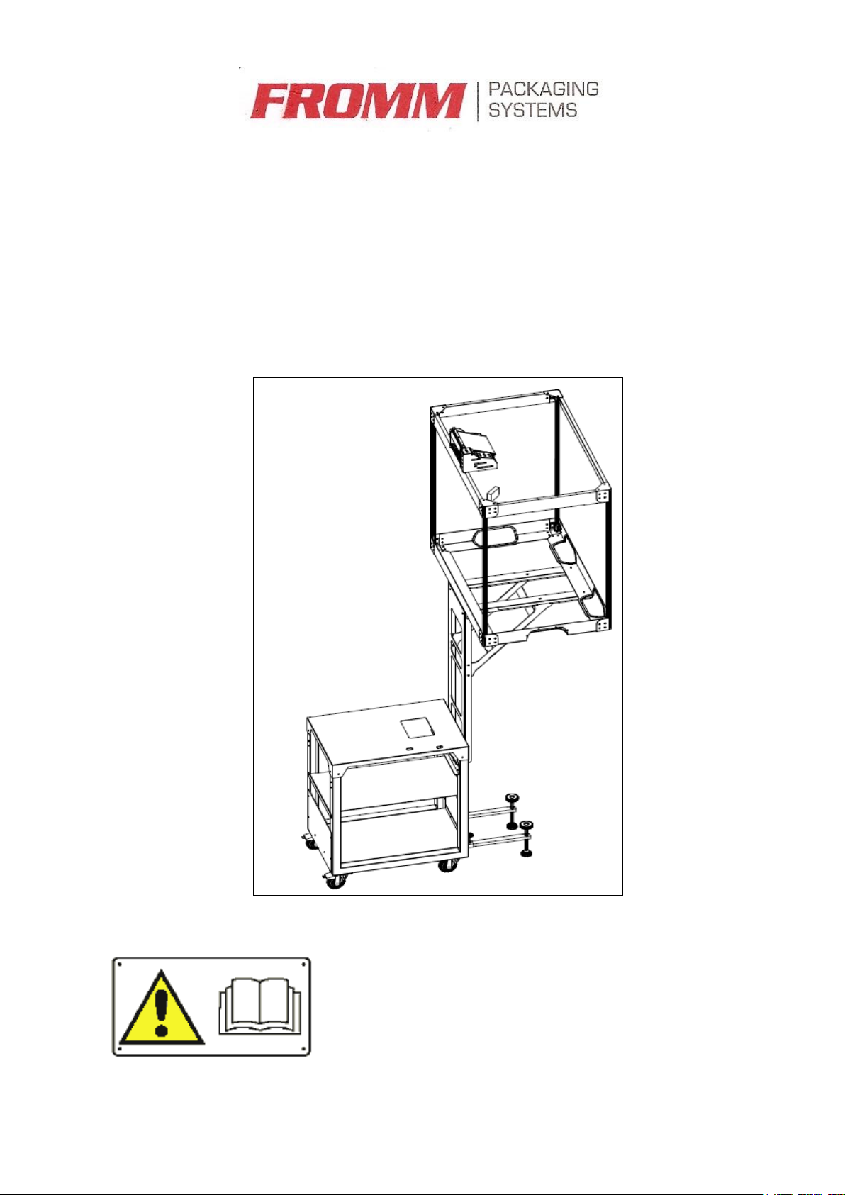
2INTRODUCTION
This document contains instructions on machine installation and startup.
Spare parts must be obtained directly from your authorized Dealer.
FROMM is always available to provide assistance to its Customers and
reiterates the fact that failure to follow the instructions provided in this
document will void the machine warranty.
In order to correctly use this machine, basic definitions for risk assessment and
safe design should be considered:
3GENERAL SAFETY INFORMATION
Do not attempt to assemble the machine without having
carefully read this Manual.
Users must always comply with the local health and safety
legislation that is applicable in the country in which the
machine is installed.
Failure to comply with the information provided in this
Manual will release CO.ME.SA.SRL from liability.

Instruction Manual
REV. 00
Hopper System for AP210
Page 5 of 17
Photocell
Trolley
Wheels
with brakes
Upright
Stabilizer
Hopper
Brackets
Feeder
4MACHINE TECHNICAL SPECIFICATIONS
The machine consists of:
Trolley on wheels (rear wheels feature brakes), featuring telescopic
stabilizer bars;
Upright;
Basket support brackets;
Hopper (pad collecting basket);
Feeder (supplied with the AP210);
Photocell
Figure 1
The machine overall dimensions are provided in mm in the Figure; total weight
in this configuration shown is 73 kg.

Instruction Manual
REV. 00
Hopper System for AP210
Page 6 of 17
5MACHINE ASSEMBLY
The machine is fitted on a platform that measures 1200 x 800. Packaging
consists of a cardboard box that is secured to the platform for stability.
The total weight of the machine and its packaging is 88 Kg.
Figure 2
After the external packaging has been removed, the machine appears as
shown in Figure 3.
Figure 3

Instruction Manual
REV. 00
Hopper System for AP210
Page 7 of 17
Machine assembly phases are described below.
5.1 Hopper assembly
The Hopper is delivered partly preassembled.
The Hopper structure is composed of:
Base with preassembled net;
Top frame;
Tubing to connect the base and the top.
The photocell and the feeder are also integral parts of the Hopper and are
supplied with the machine.
5.1.1 PHASE 1 –assembling the tubing
Place the base and its net on a flat surface, insert the tubing in the
appropriate connectors beginning on the photocell side, making sure that the
notches on the lower section are facing the photocell cord. Ensure that the
net is outside the frame created by the tubing and that it is taut.
Figure 4
Fit the remaining tubing, leaving the machined parts facing upward and
oriented in the appropriate direction to receive the net seams (see Figure 7).
Tighten the clamps as the tubing is inserted in the base.
Tubing –
photocell
side
Tubing
connector
Notching

Instruction Manual
REV. 00
Hopper System for AP210
Page 8 of 17
5.1.2 PHASE 2 - assembling the top
Slide the net down with the seams against the tubing.
Figure 5
Figure 6

Instruction Manual
REV. 00
Hopper System for AP210
Page 9 of 17
When the net is fully taut, fit the corner seams in the slots made in the tubing.
Figure 7
Position the top, making sure to pass the photocell and feeder connector
through to the opposite hole.
Figure 8
Fully tighten the clamps and insert the net seams in the appropriate slots.
Figure 9

Instruction Manual
REV. 00
Hopper System for AP210
Page 10 of 17
5.1.3 PHASE 3 - assembling the photocell and feeder
Position the photocell (on which a clamp has been preinstalled) and secure it
with a nut. Insert the connecting connector.
Figure 10
Figure 11
Position the feeder and attach it to the Hopper by inserting the screws in the
appropriate holes and securing them with the nuts (see Figure 11).
Lock nut
photocell clamp

Instruction Manual
REV. 00
Hopper System for AP210
Page 11 of 17
To fit the Hopper with a feeder that may be secured to the AP210
arm, the connecting clamp must first be removed (see Figure 12).
Figure 12
Fit the net support frame on the feeder and secure it using a screw and nut
(see Figure 13).
Figure 13
Connecting clamp

Instruction Manual
REV. 00
Hopper System for AP210
Page 12 of 17
Fit the net by securing it in the appropriate slots on the Hopper crossbar on
one side, and to the net support frame on the other (see Figure 14).
Figure 14
Insert the connector in the appropriate socket (see Figure 15).
Figure 15

Instruction Manual
REV. 00
Hopper System for AP210
Page 13 of 17
5.2 Installing the Hopper support structure
The Hopper support structure consists of an upright upon which the Hopper
support brackets have been preinstalled.
In order to correctly assemble the structure, the trolley must be placed on its
side and an adequate support must be used, as shown in Figure 16
Figure 16
Using the support, position the upright and secure it as shown in Figure 17.
Figure 17
Once the upright has been assembled, return the trolley to its initial position.

Instruction Manual
REV. 00
Hopper System for AP210
Page 14 of 17
5.3 Positioning the Hopper
Position the Hopper on the brackets by inserting the brackets in the slots at
the bottom of the Hopper (see Figure 18).
Figure 18
Attach the Hopper to the brackets using screws and nuts, as shown in
Figure 19.
Figure 19
Bracket slots

Instruction Manual
REV. 00
Hopper System for AP210
Page 15 of 17
Connect the photocell and feeder power connector, which is located at the base
of the brackets (see Figure 20 and Figure 21).
Figure 20
Figure 21
The machine is ready to be used. Connectors must be connected to the
machine as shown in Figure 22 and Figure 23.
Figure 22
3-pole
connector

Instruction Manual
REV. 00
Hopper System for AP210
Page 16 of 17
Figure 23
6POSITIONING THE STABILIZERS
The machine features stabilizers to reduce vibration during use.
The stabilizers must be extended approximately 350 mm, and the adjustable
feet must be set to allow the wheels to stay in contact with the ground.
Figure 24
5-pole
connector
Length
adjustment
knob
Height
adjustment
handwheel

Instruction Manual
REV. 00
Hopper System for AP210
Page 17 of 17
7VERIFICATIONS TO BE PERFORMED BEFORE STARTING
THE MACHINE
7.1 Environmental conditions
The machine may be operated at temperatures between +10° C and +50 °C.
The machine must not be started if exposed to poor
weather conditions; in addition, if the machine is stored
outdoors, even temporarily, it must be suitably protected
from the environment.
7.2 Lighting conditions
The work area must be sufficiently lit, at a minimum value of 500 lx.
Other manuals for AP210
1
Table of contents
Other Fromm Packaging Equipment manuals

Fromm
Fromm FS31 Series User manual

Fromm
Fromm FS130 Series User manual

Fromm
Fromm P322 Guide

Fromm
Fromm P331 M/HA Guide

Fromm
Fromm A383.0003 Guide

Fromm
Fromm P328 A/A User manual

Fromm
Fromm FS13 Series User manual

Fromm
Fromm FS33 Series User manual

Fromm
Fromm P328 M User manual

Fromm
Fromm FS11 Series User manual