Triton NMD 100 User manual

TDN 07103-00442 Rev B
©2020 Triton Systems of Delaware, LLC. All Rights Reserved. ATMGurus®, the ATMGurus logo and tag-
line, Triton®, and the Triton logo are all registered trademarks of Triton Systems of Delaware, LLC. e third
party trademarks that may be identi ed herein are the trademark of their respective owners. Triton disclaims any
affi liation, connection, or association between its products and services, and those of the respective trademark
owners, or any sponsorship or approval of its products and services by such trademark owners.
NMD 100 Extension Assembly

Triton Systems ©
2
07103-00442 Date Description
Original May 15, 2012 Unpack and assemble the NMD 100 extension
Revision B September 2, 2020 Updated images and description to unpack and assemble
the NMD 100 extension
Contact Information
Triton© Headquarters and Manufacturing Plant
21405 B Street
Long Beach, MS 39560 USA
1 (866) 259-4866
(228) 575-3101 (fax)
Triton Technical Services Department
techsvs@triton.com
1 (800) 259-6672 (opt 3)
Manufacturer warrants that the products delivered to a distributor will perform in accordance with the Manufac-
turer’s published speci cations for thirteen months from date of shipment from Long Beach, MS. Manufacturer’s
warranty shall not apply to any damage resulting from abuse, negligence or accident, or to any loss or damage
to the product(s) while in transit. Written notice and explanation of circumstances surrounding any claims that
the goods have proved defective in material or workmanship shall be given promptly from the distributor to the
manufacturer. No claim may be made, or action brought, by or through a distributor a er the expiration of 14
months following any alleged breach of warranty.
Distributor’s sole and exclusive remedy in the event of defect is expressly limited to the replacement or correc-
tion of such defective parts by manufacturer at its election and sole expense, except there shall be no obligation
to replace or repair items which, by their nature, are expendable.
ese terms and conditions shall be governed by and construed in accordance with the provisions of the Uni-
form Commercial Code as adopted by the State of Mississippi.
Due to space limitations, the bill output feed extension is being shipped with the dispenser unit, but unattached
and unassembled. is guide covers the steps for assembling and installing the extension on the NMD 100 R-12
cash dispenser. All necessary parts are included in shipment including extension blocks, cover plates and wiring,
but assembly is required. Extension length for individual units will be determined prior to shipping.
is procedure applies to all service personnel involved in the process of maintaining, converting, or upgrading
hardware and so ware on Triton ATM
is extension assembly applies to a variety of through-the-wall Triton ATM units in the U.S. and abroad. All
parts are included in shipment and directions are available to locate installation documents necessary to assem-
ble the extension and attach to dispenser

Triton Systems ©
3
Read All Instructions Before Proceeding: Triton Systems will not be responsible for items damaged or lost
during shipping, unpacking or assembly. Follow all instructions carefully.
To receive proper credit for returned units and parts, save ALL packing contents
for reshipping. Repack all items being returned in the same manner new parts
were originally shipped. Failure to do so may result in lost or delayed credit for
inappropriately packaged items.
Caution
When unpacking contents, use caution when removing the upper box tray covering extension parts. Remove
contents and place on top of dispenser unit without stretching or pulling wiring. Take note of any damage to
contents and make sure wiring contacts are attached tightly to dispenser unit and extension end.
TOOLS REQUIRED T-10 Torx Drivers
PARTS All necessary parts and hardware are included in shipment
Table of Contents
..............................................................................................
..............................................................................................................
...................................................................................................................
.......................................................................................................
.......................................................................................
.............................................................................
............................................................
.......................................................................................
” ...............................................................................
” .............................................................................

Triton Systems ©
4
Figure 1
NMD 100 with BOU extension, cover plates and li ing handles attached
. B O U (BOU) -- is part is shipped with the ground and exit sensor cables attached. Use
caution not to put tension on wiring while unpacking item.
. E B -- ese blocks t together to make up a length of extension. Number of blocks sent
will be determined by unit model. Blocks are secured with Torx-head screws.
. T C P -- Upper rear plate is not fastened and folds upward from top of unit to remove. Front
plate is held in place by ve (5) Torx-head screws. Plates are taped during shipping.
. N S M -- Inspect motor and mount for any damage that may have occurred during ship-
ping. Make sure the wiring cable is properly seated and the unit is snug on the chassis.
. L H -- ese are shipped separately from the unit.
. W G/CMC B -- Ground wire, ( ve-inch, or 10-inch, depending on extension) is
routed down arm to attach to ground point on chassis. Exit sensor cable, (black ribbon wire) routes across
outside of dispenser to connect to CMC board. Keep wiring away from movable parts.
. CMC B/C P -- e CMC board is protected by a metal cover plate. Extension control wire
plugs into tting on CMC board.
. N Q D -- Make certain doors remain snapped closed a er shipping.
9. Li Points -- Grasp the li points. Li dispenser straight up then out of inner box.

Triton Systems ©
5
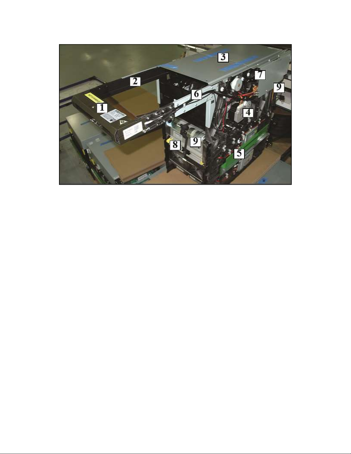
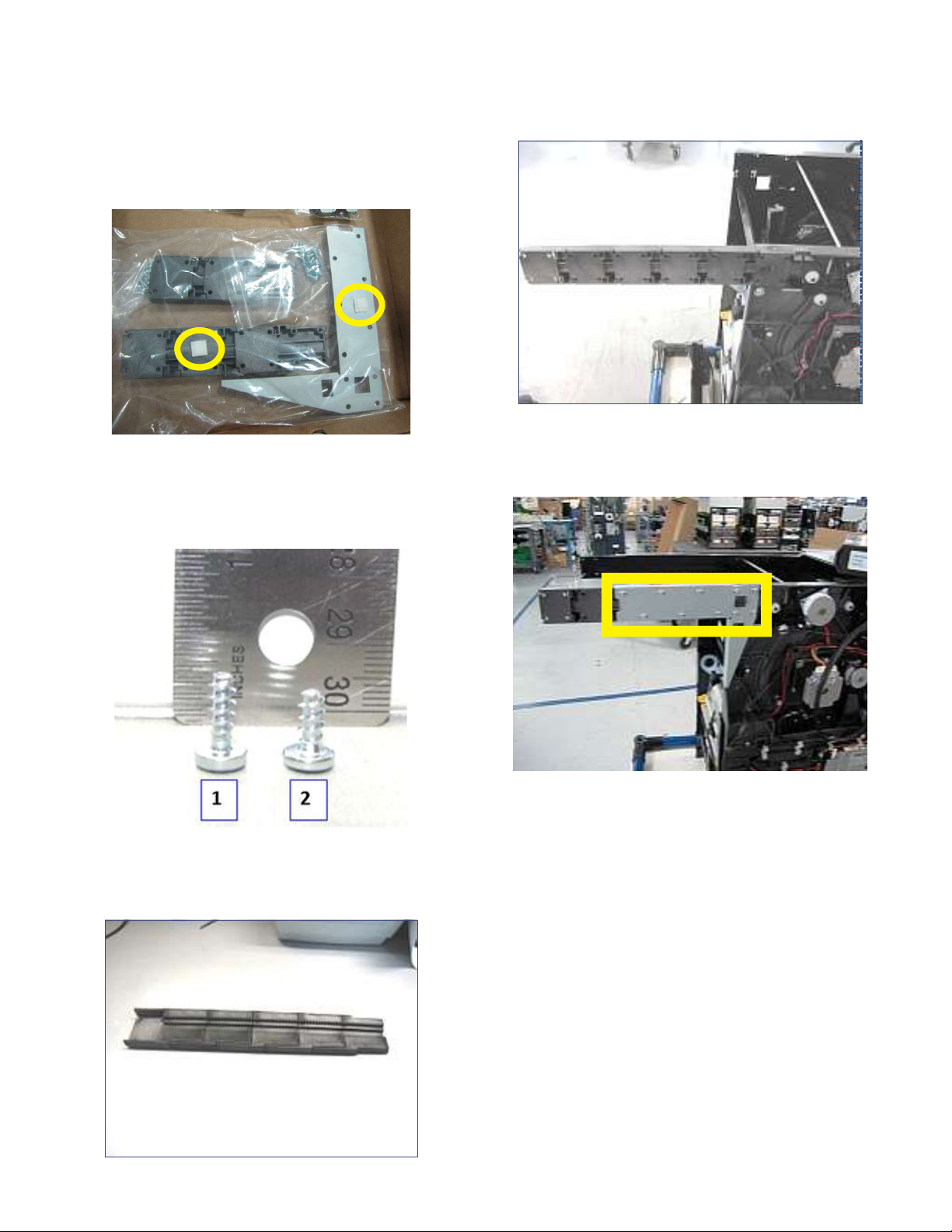
1. Do not remove the inner box. Use the inner and
outer boxes for repackaging and shipping. Save all
packing material for re-use in return shipment, the
four (4) corner cushions, (Figure 2A), green air
llers, and the cardboard tray (Figure 2B).
Figure 2A Figure 2B
Caution
e BOU with cable is connected to the NMD100
chassis. Do not damage the cable in the process of
removing the BOU and the dispenser from the box.
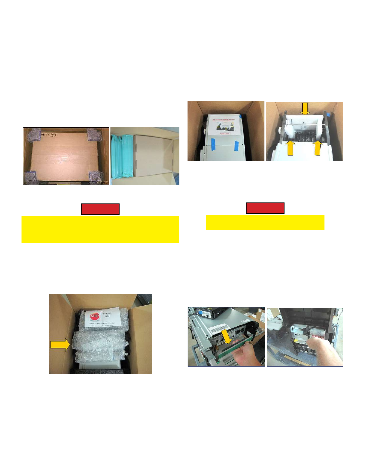
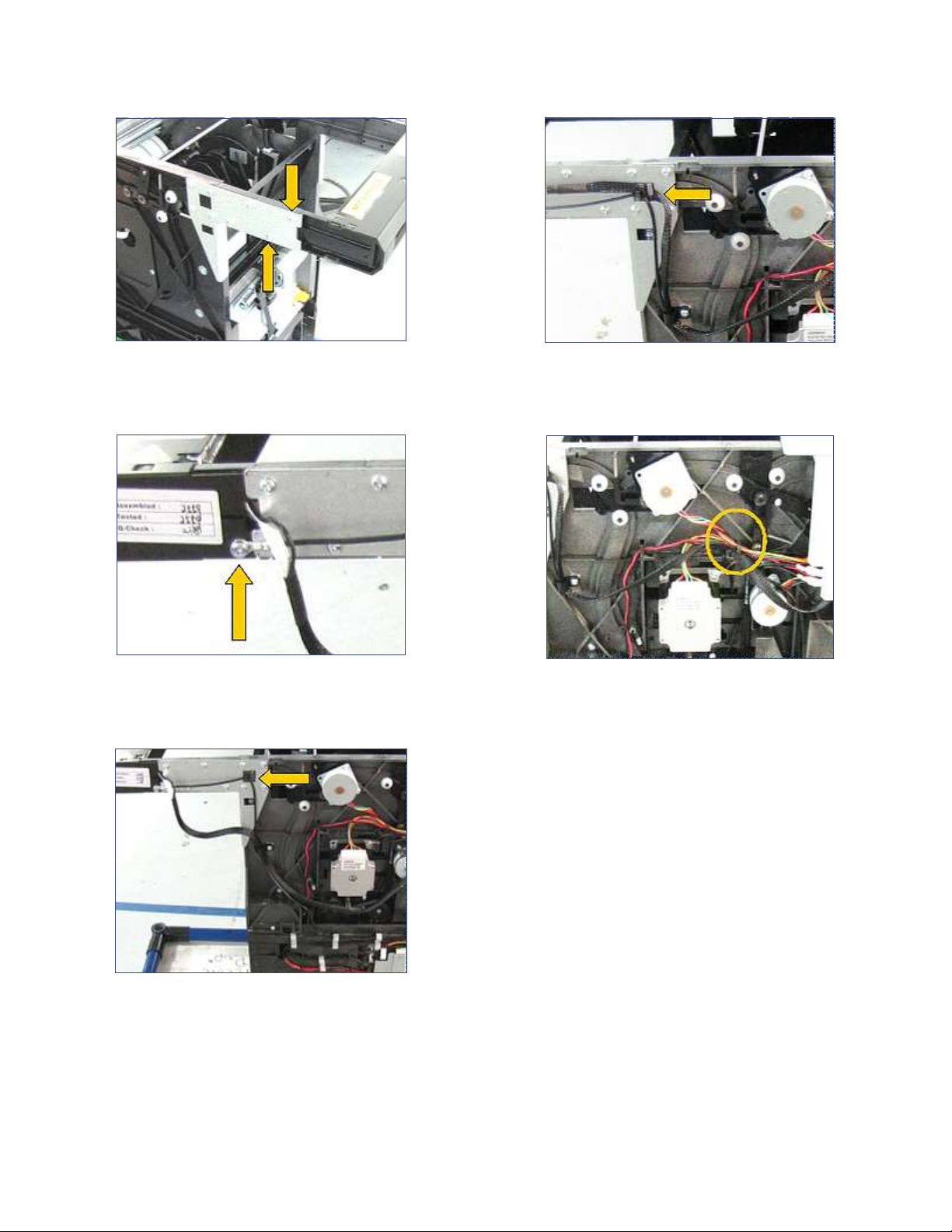
2. (Figure 3A), remove the extension kit (Yellow ar-
row) and set aside. Hold the BOU with the (STOP)
label out of the way until ready to li the dispenser
from the box.
Figure 3A
3. Remove and set aside the packing foam from the
top and sides of the dispenser. All returns must be
received with original packing material.
4. Remove the top cover with the internal foam label.
No fasteners hold the cover in place, (Figure 3B).
Remove the 3 pieces of BCU retaining foam from
**Note**
Before proceeding, follow these steps to properly unpack the contents and prepare for assembly of the Bundle
Output Unit extension and its attachment to the NMD 100 dispenser. Save all packing materials for use in
returning unit.
the unit, (Figure 3C). Set aside with the other
foams for reshipment.
Figure 3B Figure 3C
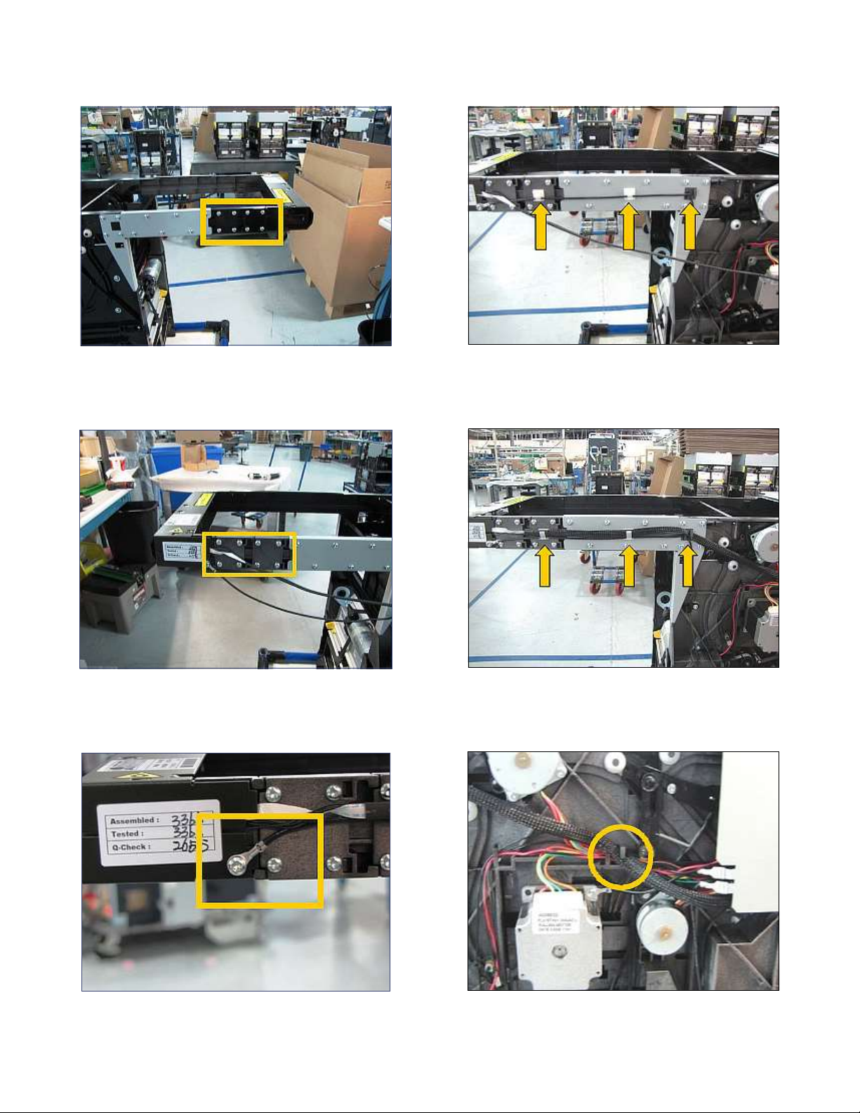
5. Rest the BOU on top of the dispenser, (Figure 4A).
Caution
e NMD100 is a two-person li .
6. Li handles will not be shipped with the unit. To
remove the unit, reach in front and grip the upper
dispenser bracket, (Figure 4A). Reach behind the
unit and grip the main motor housing, (Figure
4B). Li the dispenser straight up, then out of the
inner box. Place the unit on a sturdy work table to
complete the assembly.
Figure 4A Figure 4B
7. Examine the BOU, parts kit, and the dispenser’s
outside and inside areas for cracks or damages
caused by shipping. Inspect wiring connections.
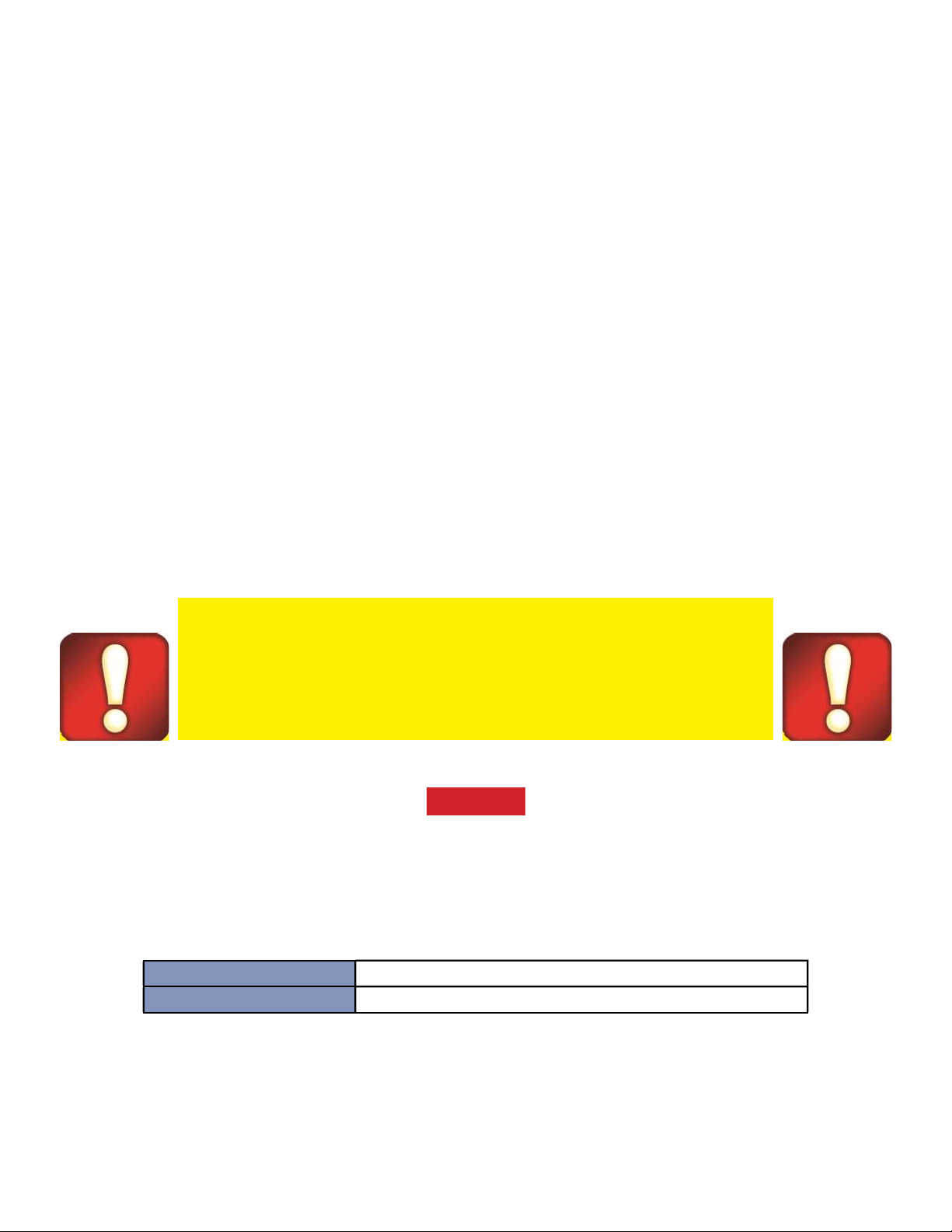
Ensure note quali er doors (Figure 1) are snapped
closed.
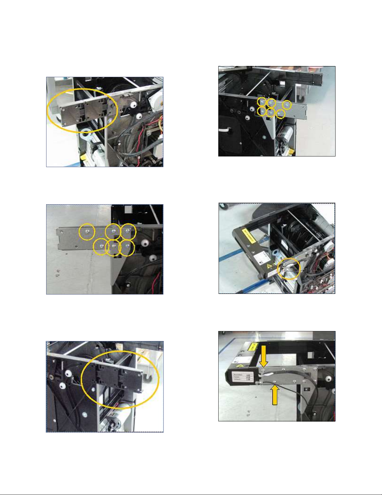
8. See instructions for installing a 5” or 10” extension
assembly below.

Triton Systems ©
6
”
1. Obtain two of the dull gray extension pieces and
snap them together on the dull side as shown
below.
2. Attach the metal brace using six screws as shown
below.
3. Obtain two of the shiny gray extension pieces and
snap them together on the shiny side as shown
below.
4. Attach the metal brace using six screws as shown
below.
5. Snap the BOU into place as shown below. Ensure
the cables are not damaged or pinched when in-
stalling the BOU.
6. Secure the BOU to the dispenser with two screws
as shown below.

Triton Systems ©
7
7. Secure the opposite side of the BOU to the dis-
penser with two long screws as shown below.
8. Move the BOU ground wire so that it is in the posi-
tion shown below.
9. Place the ground wire into the clip marked with an
arrow as shown below.
10. Place the mesh covered cable into the clip as shown
below.
11. Place the mesh covered cable into the clip shown
below.
is completes the 5” extension installation. Install the
NMD 100 dispenser into the ATM.

Triton Systems ©
8
”
**Note**
Adhesive wire clips are installed on the metal bracket
and one of the extension blocks. Not all images show
the clips, but are shown in step 13.
e longer #1 screw used to attach the metal bracket.
e shorter #2 screw used to secure the plastic exten-
sion blocks.
1. Obtain the ve dull gray extension pieces and snap
them together as shown below.
2. Install the extension pieces on the dull gray side as
shown below.
3. Attach the metal brace using 10 of the long #1
screws as shown below.

Triton Systems ©
9
4. Obtain the ve shiny gray extension pieces and the
extension bracket as shown below.
**Note**
Not all kits will be received this way. Assemble as need-
ed to achieve the results shown in step 6.
5. Slide one piece into the bracket as shown below.
6. Slide two pieces into the other end as shown below.
7. Slide the assembly into place as shown below.
8. Attach the metal brace using eight of the long #1
screws as shown below.
9. Snap the BOU into place as shown below. Ensure
the cables are not damaged or pinched when in-
stalling the BOU.

Triton Systems ©
10
13. Place the ground wire into both the white clips
then into the black clip as shown below.
14. Place the mesh covered wire into both white clips
then place into the black clip as shown below.
15. Place the mesh covered cable into the clip as shown
below.
is completes the 10” extension installation. Install
the NMD 100 dispenser into the ATM.
10. Secure the BOU to the dispenser with eight of the
#2 short screws as shown below.
11. Secure the other side of the BOU to the dispenser
with eight of the short #2 screws as shown below.
12. Move the BOU ground wire so that it is in the posi-
tion shown below.
Table of contents
Popular Packaging Equipment manuals by other brands

Fromm
Fromm A383.0003 Operation manual & spare parts list

Rotochopper
Rotochopper Go-Bagger 250 quick start guide

Orgapack
Orgapack 100 Series Operating and safety instructions

XtraVac
XtraVac CM430 Operations & parts manual

PIY Ribbons
PIY Ribbons Startkit manual

Minipack-Torre
Minipack-Torre Galileo Installation, operation and maintenance

CAMPAGNOLO
CAMPAGNOLO C 95 1-2 Use and maintenance manual

Kaiser+Kraft
Kaiser+Kraft BW-01 Operation manual and parts list

Orgapack
Orgapack CR 208 P Operating and safety instructions

Extend
Extend EXS-125 Operation & maintenance manual

Pro Mach
Pro Mach Wexxar BEL Series Operation & service manual

U-Line
U-Line H-5334 quick start guide