AEMC K100 User manual

ENGLISH
nDC/AC MICROPROBE K100
K110
User Manual
• OFF
• 1 mV/mA
ON OL
AEMC
INSTRUMENTS
®DC/AC MicroProbe
Model K100
!
www.ShopAEMC.com
Shop for AEMC products online at: 1.877.766.5412

Statement of Compliance
Chauvin Arnoux®, Inc. d.b.a. AEMC®Instruments
certifies that this instrument has been calibrated
using standards and instruments traceable to
international standards.
We guarantee that at the time of shipping your
instrument has met its published specifications.
An NIST traceable certificate may be
requested at the time of purchase, or obtained
by returning the instrument to our repair and
calibration facility, for a nominal charge.
The recommended calibration interval for this
instrument is 12 months and begins on the date of
receipt by the customer. For recalibration, please
use our calibration services. Refer to our repair
and calibration section at www.aemc.com.
Serial #: ________________________________
Catalog #: 1200.67 / 2111.73
Model #: K100 / K110
Please fill in the appropriate date as indicated:
Date Received: _________________________________
Date Calibration Due: _______________________
Chauvin Arnoux®, Inc.
d.b.a AEMC®Instruments
www.aemc.com
www.ShopAEMC.com
Shop for AEMC products online at: 1.877.766.5412

Table of Contents
1. INTRODUCTION............................................................................... 3
1.1 International Electrical Symbols................................................3
1.2 DenitionofMeasurementCategories .....................................4
1.3 ReceivingYourShipment..........................................................4
1.4 OrderingInformation.................................................................4
2. PRODUCT FEATURES ...................................................................... 5
2.1 Description................................................................................5
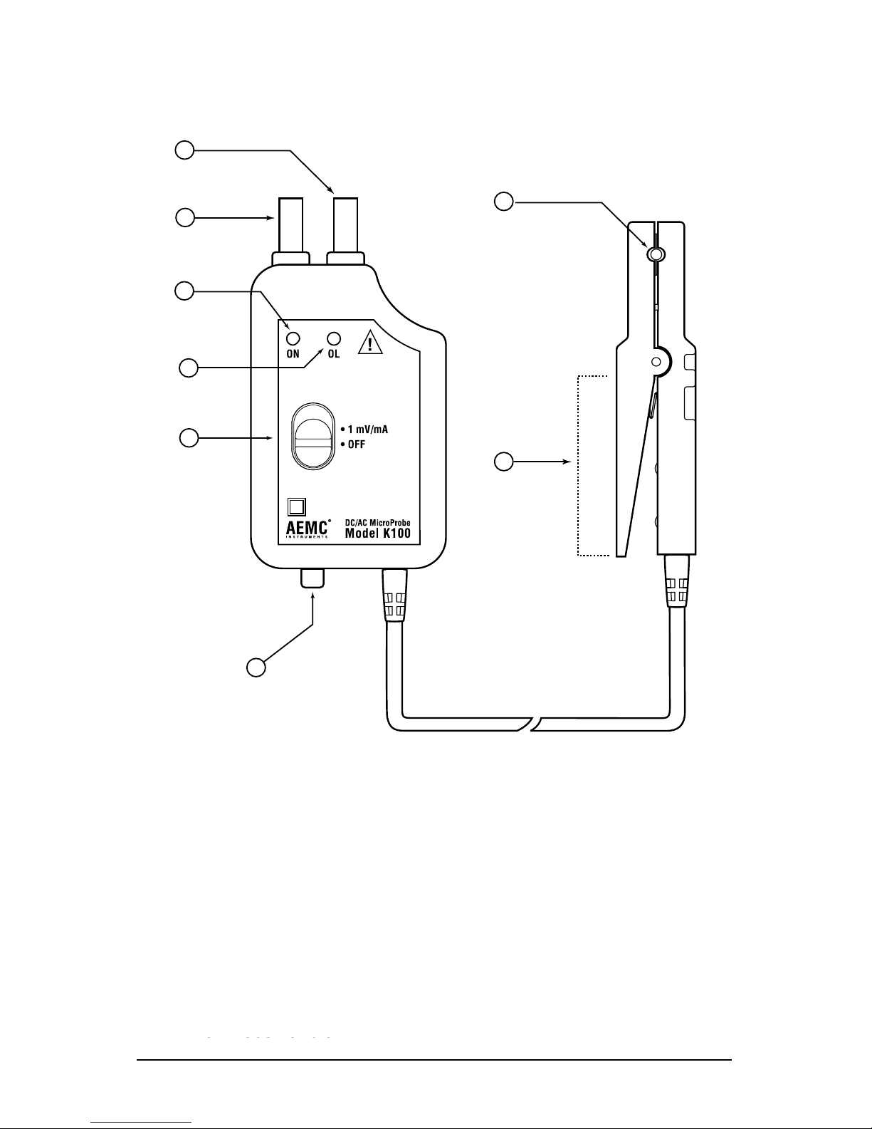
2.2 ModelK100Features ...............................................................6
2.3 ModelK110Features................................................................7
3. SPECIFICATIONS............................................................................. 8
3.1 ElectricalSpecications ............................................................8
3.2 EnvironmentalSpecications....................................................9
3.3 MechanicalSpecications ........................................................9
3.4 SafetySpecications ................................................................9
3.5 TypicalFrequencyResponse .................................................10
4. OPERATION .................................................................................. 11
4.1 MakingMeasurementswiththeK100/K110 ........................... 11
4.2 IndicatorLights-GreenandRedLEDs.................................. 11
4.3 ModelK100OperationExamples ...........................................12
DCCurrentMeasurementExample(K100) ..............................12
DCCurrentMeasurementExample-CurrentReversed........12
Two-WireSum-of-CurrentsExample(K100) ............................13
Two-WireCurrentDifferentialExample(K100).........................13
OscilloscopeMeasurementExample(K100)............................14
MaximumStepDiscontinuityExample(K100)..........................14
4.4 ModelK110OperationExamples ...........................................15
MeasuringtheDCComponentofan(AC+DC)Waveform ....15
MeasuringtheACComponentofan(AC+DC)Waveform ......15
OscilloscopeMeasurementExample(K110)............................16
4.5 TipsForMakingPreciseMeasurements ................................16
4.6 ResidualReadingsFollowingSevereOverloads....................19
www.ShopAEMC.com
Shop for AEMC products online at: 1.877.766.5412

5. MAINTENANCE ............................................................................. 20
5.1 Warning..................................................................................20
5.2 Battery Installation ..................................................................20
5.3 Cleaning..................................................................................21
RepairandCalibration...........................................................................22
TechnicalandSalesAssistance ............................................................22
LimitedWarranty ...................................................................................23
WarrantyRepairs...................................................................................23
www.ShopAEMC.com
Shop for AEMC products online at: 1.877.766.5412

DC/AC MicroProbe Models K100 and K110
3
CHAPTER 1
INTRODUCTION
WARNING
Thesesafetywarningsareprovidedtoensurethesafetyofpersonnel
andproperoperationoftheinstrument.
• Readtheinstructionmanualcompletelyandfollowallthesafety
informationbeforeattemptingtouseorservicethisinstrument.
• Use caution on any circuit: Potentially high voltages and cur-
rentsmaybepresentandmayposeashockhazard.
• ReadtheSafetySpecicationssectionpriortousingtheModel
K100/K110.Neverexceedthemaximumvoltageratingsgiven.
• Safetyistheresponsibilityoftheoperator.
• NEVERopenthebackoftheinstrumentwhileconnectedtoany
circuitorinput.
• ALWAYSconnecttheModelK100/K110adaptertothedisplay
devicebeforeclampingtheprobeontothesampleundertest.
• ALWAYS inspect the instrument, probe, probe cable and
output terminals prior to use. Replace any defective parts
immediately.
• NEVER use the Model K100/K110 on electrical conductors
ratedabove300VCATII,EN61010-1.
1.1 International Electrical Symbols
Thissymbolsigniesthattheinstrumentisprotectedbydoubleor
reinforcedinsulation.Useonlyspeciedreplacementpartswhen
servicingtheinstrument.
This symbol on the instrument indicates a WARNING and that
theoperatormustrefertotheusermanualforinstructionsbefore
operating the instrument. In this manual, the symbol preceding
instructions indicates that if the instructions are not followed,
bodilyinjury,installation/sampleandproductdamagemayresult.
Riskofelectricshock.Thevoltageatthepartsmarkedwiththis
symbolmaybedangerous.
www.ShopAEMC.com
Shop for AEMC products online at: 1.877.766.5412

4
DC/AC MicroProbe Models K100 and K110
1.2 Definition of Measurement Categories
CAT I: FormeasurementsoncircuitsnotdirectlyconnectedtotheAC
supply wall outlet such as protected secondaries, signal level,
andlimitedenergycircuits.
CAT II: For measurements performed on circuits directly connected to
the electrical distribution system. Examples are measurements
onhouseholdappliancesorportabletools.
CAT III: For measurements performed in the building installation at
the distribution level such as on hardwired equipment in xed
installationandcircuitbreakers.
CAT IV: For measurements performed at the primary electrical supply
(<1000V) such as on primary overcurrent protection devices,
ripplecontrolunits,ormeters.
1.3 Receiving Your Shipment
Uponreceivingyourshipment,makesurethatthecontentsareconsistent
with the packing list. Notify your distributor of any missing items. If the
equipmentappearstobedamaged,leaclaimimmediatelywiththecar-
rierandnotifyyourdistributoratonce,givingadetaileddescriptionofany
damage.
1.4 Ordering Information
DC/AC MicroProbe Model K100.......................................... Cat. #1200.67
DC/AC MicroProbe Model K110.......................................... Cat. #2111.73
Both models include an electronic plug-in module with an attached current probe, 9V battery,
and user manual
Order Accessories and Replacement Parts Directly Online
Check our Storefront at www.aemc.com/store for availability
www.ShopAEMC.com
Shop for AEMC products online at: 1.877.766.5412

DC/AC MicroProbe Models K100 and K110
5
CHAPTER 2
PRODUCT FEATURES
2.1 Description
ModelK100andModelK110arelowcurrentmeasurementinstruments
thatfeatureacompact,highsensitivitycurrentprobe.Unlikeotherinstru-
ments,theModelK100exhibitsawidedynamicoperatingrange,which
extendsfrombelow100µAto±4.5Apeak,fromDCto2.0kHz*,withoutthe
needforranging.TheK110hasanoperatingrangeof100µAto±450mA
Peak,fromDCto1500Hz.*
ModelsK100andK110aredesignedtobeoperatedinconjunctionwitha
digitalmultimeter,oscilloscopeorrecordingdevice.TheMicroProbeout-
putsthecurrentmeasuredintheformofavoltagethatistheimageofthe
current,inshapeandamplitude.TheModelK100outputs1mVpermAof
measuredcurrent.TheModel K110outputs 10mVpermA ofmeasured
current.TotakeadvantageoftheModelK100highsensitivity,bestresults
areobtainedthrough4-1/2digit(ormore)DMMwitharelativezerofunc-
tion.TheModelK110wasdesignedtoprovidetheoperatorwithenhanced
lowcurrentlinearityandaccuracy,butislimitedto450mAPeakcurrent.
The Model K100/K110 always outputs a signal proportional to the total
current(AC+DC)intheconductorundertest.Thishasproventobethe
most versatile signal output format, and allows the user to isolate and
measureDCandAC componentsofmeasuredcurrent separately,ifso
desired.Typicalapplicationsinclude4to20mAloopmeasurements,auto-
motive current applications, benchtop electronic current consumption in
circuits,andotherapplicationsrequiringverylowcurrentmeasurements
incrowdedareas.
* See Electrical Specications
www.ShopAEMC.com
Shop for AEMC products online at: 1.877.766.5412

6
DC/AC MicroProbe Models K100 and K110
2.2 Model K100 Features
8
7
1
2
3
4
5
6
Figure 1
1.Positive:Redbananaplug(+)
2.Negative:Blackbananaplug(-)
3.PowerONindicator(greenLED)
4.OVERLOADindicator(redLED)
5.Powerswitch
6.Zeroadjustknob(pushinandturntozero)
7.Probewindowaperture
8.Probehandle
www.ShopAEMC.com
Shop for AEMC products online at: 1.877.766.5412

DC/AC MicroProbe Models K100 and K110
7
2.3 Model K110 Features
®
8
7
1
2
3
4
5
6
Figure 2
1.Positive:Redbananaplug(+)
2.Negative:Blackbananaplug(-)
3.PowerONindicator(greenLED)
4.OVERLOADindicator(redLED)
5.Powerswitch
6.Zeroadjustknob(pushinandturntozero)
7.Probewindowaperture
8.Probehandle
www.ShopAEMC.com
Shop for AEMC products online at: 1.877.766.5412

8
DC/AC MicroProbe Models K100 and K110
CHAPTER 3
SPECIFICATIONS
3.1 Electrical Specifications
Model K100
Current Range:
0to±4.5ADC
0to3Arms(sinusoidal)
Output (Vout):1mV/mA
Resolution:
DC:50µAtypical
AC:100µAtypical
Accuracy:
DC:1%reading±200µA
AC:2%reading±200µA
Output Noise:
<100µV,DCto3kHz
Frequency Response:
DCto2kHz(@-3dBsine)
Zero Adjust:
±25mA
Model K110
Current Range:
0to±450mADC
0 to 300mA rms
Output (Vout): 10mV/mA
Resolution:
DC:50µAtypical,
AC:100µAtypical
Accuracy:
DC:0.5%reading±150µA
AC:0.8%reading±200µA
Output Noise:
<100µV,DCto3kHz
Frequency Response:
DCto1.5kHz(@-3dBsine)
Zero Adjust:
±25mA
Rise Time: <200µS,10%to90%Vout
Fall Time: <200µS,90%to10%Vout
Output Impedance: 200Ω
Probe Inductance: <1µH
Inuence of Adjacent Conductor: <50µA/A(K100);<100µA/A(K110)
Inuence of Earth’s Field:<120µA,nulltomaximum
Overload LED (Red):Indicatesmomentaryorcontinuousoverload
Power LED (Green): IndicatespowerONandgoodbattery
LED(Green)ONbetween6.5to10V
Power Source: 9Valkaline,NEDA1604,6LR61orIEC6LF22
Batterylife20Happrox.withalkalinebattery
(Reference Conditions: 23°C ± 3°, 20 to 75% RH; battery voltage 9V ± 0.1V; earth’s magnetic
eld < 40 A/m; absence of AC elds; input impedance of display device ≥ 1MΩ/100 pF; DC
or sinusoidal AC current 45 to 65Hz.)
www.ShopAEMC.com
Shop for AEMC products online at: 1.877.766.5412

DC/AC MicroProbe Models K100 and K110
9
3.2 Environmental Specifications
Operating Temperature: -14°to131°F(-10°to55°C)
Storage Temperature:-40°to176°F(-40°to80°C)
Humidity: <95%@≤35°C,75%@55°C
3.3 Mechanical Specifications
Dimensions (Probe): 4.4x0.6x1.0"(111x15x25mm)
Dimensions (Electronic Module): 4.9x2.5x1.1"(124x64x28mm)
Weight: 9oz(250g)
Connectors: Two4mmbananaplugs;standard3/4"(19mm)spacing
Maximum Conductor Diameter: 3/16",0.180"(4.5mm)
Cable Length: 5ft(1.5m)
3.4 Safety Specifications
Working Voltage:
EN61010-1,300VCATII
CEmarkforElectromagneticCompatibility.
Immunity(EN50082.1),IEC1000-4-3aptitudecriteriaA:
DC:15mV@0,AC(60Hz):2dBfrom10mAto4.5A
Emmissivity(EN50081.1):negligible
Drop Test:1mperIEC1010
Shocks:100GperIEC68-2-27
Vibrations: IEC 529
Protection Index:IP40perIEC529
Electromagnetic Compatibility:
EN50082-1classAEN50081-1
*All specications are subject to change without notice.
www.ShopAEMC.com
Shop for AEMC products online at: 1.877.766.5412

10
DC/AC MicroProbe Models K100 and K110
3.5 Typical Frequency Response
Model K100
2200
2000
1800
1600
1400
1200
1000
800
600
400
200
50
0
-0.5
-1.0
-1.5
-2.0
-2.5
-3.0
-3.5
-4.0
30 mA
3.0 A
Frequency (Hz)
Decibels (dB)
Figure 3
Model K110
1600
1400
1200
1000
800
600
400
200
0
0
-0.5
-1.0
-1.5
-2.0
-2.5
-3.0
-3.5
-4.0
0 - 300 mA RMS
Frequency (Hz)
Decibels (dB)
Figure 4
www.ShopAEMC.com
Shop for AEMC products online at: 1.877.766.5412

DC/AC MicroProbe Models K100 and K110
11
CHAPTER 4
OPERATION
4.1 Making Measurements with the K100/K110
• Removeanyconductorfromwithintheprobejaws.
• Plugtheelectronicmoduleintothedisplayingdevice(e.g.,DMM,oscil-
loscope).Notethepolarityofthemoduleoutputbananaplugs(red=
positive[+],black=negative[-]).
• Selecttheappropriaterangeondisplayingdevice(e.g.,DMM,oscil-
loscope).Notethatthemoduleoutputis1mV/mAforModelK100and
10mV/AformodelK110.
• TurndisplayingdevicepowerON.TurnontheModelK100/K110(the
greenLEDshouldbeON,andtheredLEDOFF).
• Withtheprobedisconnectedfromtestsamples(noconductorinprobe
jaw window), adjust the zero control (push in the knob and turn) to
readzerovoltsonthedisplayingdevice.Intheunlikelyeventwhere
thezeropointisunobtainable,refertoResidual Readings Following
Severe Overloads(§4.6)-theModelK100/K110probemaybetem-
porarilymagnetized.
• Clamp the probe around the conductor to be tested. The displaying
deviceshouldnowdisplaythemeasuredconductorcurrent.InDC,a
positivereadingindicatescurrentowinginthedirectionofthearrow
ontheprobe.Anegativereadingindicatescurrentowintheopposite
directionofthearrow.
4.2 Indicator Lights - Green and Red LEDs
• TheGreenLEDindicatesthattheModelK100/K110isONandthatthe
batteryisgood.TheGreenLEDwillnotlightunderlowbatterycondi-
tions.Replacethe9VbatteryifthegreenLEDisnotlit.
• The Red LED indicates a momentary or continuous overload of the
instrument.ReadingstakenwhiletheRedLEDisONorFLASHING
shouldbeconsideredinaccurate.Momentary or continuouscurrents
exceeding ± 4.7A for Model K100 and 470mA for Model K110, and
dynamiccurrentswithlargestepdiscontinuitieswillcausetheredLED
toturnON.
www.ShopAEMC.com
Shop for AEMC products online at: 1.877.766.5412

12
DC/AC MicroProbe Models K100 and K110
4.3 Model K100 Operation Examples
DC Current Measurement Example (K100)
• Conductorcarrying20.0mADCinthedirectionofthearrow
• VoltmeterplacedinDCVoltsmode
• Voltmeterdisplays20.0mV
20 mA DC
PUSH
DC Zero
20.0 mV
A
C
V
D
C
V
Figure 5
DC Current Measurement Example - Current Reversed (K100)
• Conductorcarrying20.0mADCinoppositedirectionofarrow
• VoltmeterplacedinDCVoltsmode
• Voltmeterdisplays-20.0mV
20 mA DC
PUSH
DC Zero
-20.0 mV
A
C
V
D
C
V
Figure 6
www.ShopAEMC.com
Shop for AEMC products online at: 1.877.766.5412

DC/AC MicroProbe Models K100 and K110
13
Two-Wire Sum-of-Currents Example (K100)
• Twoconductorsinprobeaperture(noteorientations)
• VoltmeterplacedinDCVoltsmode
• Voltmeterdisplays18.0mV
PUSH
DC Zero
18.0 mV
A
C
V
D
C
V
7 mA DC 11 mA DC
Figure 7
Two-Wire Current Differential Example (K100)
• Twoconductorsinprobeaperture(noteorientations)
• VoltmeterplacedinDCVoltsmode
• Voltmeterdisplays-4.0mV
PUSH
DC Zero
-4.0 mV
A
C
V
D
C
V
7 mA DC 11 mA DC
Figure 8
www.ShopAEMC.com
Shop for AEMC products online at: 1.877.766.5412

14
DC/AC MicroProbe Models K100 and K110
Oscilloscope Measurement Example (K100)
• Conductorcarryinga2ApeakACwaveform
• ModelK100connectedtooscilloscope
0
To Oscilloscope
Current Waveform
Oscilloscope
Output
• OFF
• 1 mV/mA
ON OL
AEMC
INSTRUMENTS
®DC/AC MicroProbe
Model K100
0
2.0 A
2.0 V
-2.0 V
Figure 9
Maximum Step Discontinuity Example (K100)
• Conductorcarryingnon-sinusoidalAC
• ModelK100connectedtooscilloscope
• Maximumallowablestep-discontinuity2A
0
To Oscilloscope
Current Waveform
Oscilloscope
Output
• OFF
• 1 mV/mA
ON OL
AEMC
INSTRUMENTS
®DC/AC MicroProbe
Model K100
0
2A
2.0 V
-2.0 V
-2A
Note: Step Discontinuities
Figure 10
www.ShopAEMC.com
Shop for AEMC products online at: 1.877.766.5412

DC/AC MicroProbe Models K100 and K110
15
4.4 Model K110 Operation Examples
Measuring the DC Component of an (AC+DC) Waveform (K110)
• Conductorcarrying20.0mADC+15.0mAAC
• VoltmeterplacedinDCVoltsmode
• Voltmeterdisplays200.0mV
15 mA AC
+
20 mA DC
PUSH
DC Zero
200.0 mV
A
C
V
D
C
V
Figure 11
Measuring the AC Component of an (AC+DC) Waveform (K110)
• Conductorcarrying20.0mADC+15.0mAAC
• VoltmeterplacedinACVoltsmode
• Voltmeterdisplays150.0mV
PUSH
DC Zero
150.0 mV
A
C
V
D
C
V
15 mA AC
+
20 mA DC
Figure 12
www.ShopAEMC.com
Shop for AEMC products online at: 1.877.766.5412

16
DC/AC MicroProbe Models K100 and K110
Oscilloscope Measurement Example (K110)
• Conductorcarryinga0.2ApeakACwaveform
• ModelK110connectedtooscilloscope
0
To Oscilloscope
Current Waveform
Oscilloscope
Output
• OFF
• 10 mV/mA
ON OL
AEMC
INSTRUMENTS
®DC/AC MicroProbe
Model K110
0
0.2 A
2.0 V
-2.0 V
-0.2 A
Figure 13
4.5 Tips For Making Precise Measurements
TheModelK100/K110iscapableofmakingmeasurementsofDCandlow
frequencycurrentsoverawiderange.Herearesomekeyconsiderations
forgettingthemostaccuracyfromyourdisplayinginstrument:
• WhenusingtheModelK100/K110withameter,itisimportantto
selecttherangethatprovides the best resolution.Failuretodo
thismayresultinmeasurementerrors.Theexamplesshownon
thenextpageuseanordinary3-1/2digitDMMwiththeModels
K100andK110,tomeasure16.7mADC.
www.ShopAEMC.com
Shop for AEMC products online at: 1.877.766.5412

DC/AC MicroProbe Models K100 and K110
17
Model K100
16.7mA
PUSH
DC Zero
2
0
V
2
V
2
0
0
m
V
PUSH
DC Zero
.02 V
2
0
V
2
V
2
0
0
m
V
PUSH
DC Zero
2
0
V
2
V
2
0
0
m
V
Resolution: 10mV
Display Error: 19.8%
Resolution: 1mV
Display Error: 1.8%
Resolution: 100µV
Display Error: 0%
Figure 14
Model K110
PUSH
DC Zero
2
0
V
2
V
2
0
0
m
V
PUSH
DC Zero
2
0
V
2
V
2
0
0
m
V
PUSH
DC Zero
2
0
V
2
V
2
0
0
m
V
Resolution: 10mV
Display Error: 1.8%
Resolution: 1mV
Display Error: 0%
Resolution: 100µV
Display Error: 0%
16.7mA
Figure 15
www.ShopAEMC.com
Shop for AEMC products online at: 1.877.766.5412

18
DC/AC MicroProbe Models K100 and K110
• Always zero the Model K100/K110 prior to making a measure-
ment.See§4.1forprocedure.
• Makesurethatprobejawmatingsurfacesarefreeofdustand
contamination. Contaminants cause air gaps between sensor
halves, making the Model K100/K110 susceptible to external
magneticeldswhichcancontributetomeasurementerrors.See
§5.3forcleaningprocedure.
• Donotallow probejawstoabruptly snapclosedfromthe open
state. This can lead to residual readings. If this happens, the
ModelK100/K110willneedtoberezeroed.
• Bewareofshort-circuitcurrents.Largein-rushcurrents(whichcan
occurwhenpowerisrstappliedinacircuit)andlargehigh-cur-
renttransientsmaycausevaryingdegreesofresidualreadings.
Ifindoubtofaparticularreading,removetheprobefromthecon-
ductorundertestandchecktoseethatthedisplaydevicereturns
zero.Ifnot,itwillbenecessarytorezerotheModelK100/K110.
• WhenusingtheModelK100/K110tomeasureACcurrents,keep
inmindthemaximumcurrentratingsandthefrequencyresponse
curves shown in the electrical specications section. Dynamic
currentsthatcontainlargestepdiscontinuitiesand/orfrequency
constituents near or beyond the measurement passband are
subject to measurements errors and waveform distortion (oscil-
loscopedisplay).IftheredLEDcomesonduringmeasurement,
theMicroProbe’soutputsignalmaybeinerror.
ManyDVMsprovidenull(relative)measurementcapability.ADVMplaced
inthenullmodedisplaysthedifferencebetweenastorednullvalueand
theinputsignal.
• YoucanuseaDVM’snullfunctioninplaceoftheexternalDCzero
control to cancel any DC offset from the K100/K110. The DVM
nullfunctionshouldbeenabledwiththeproberemovedfromthe
conductorimmediatelybeforemeasurement.
• You can use a DVM’s null function to display changes in mea-
suredcurrentfromaxed(constant)level.Inthisapplication,the
DVMnullfunctionisenabledwiththeprobeconnectedtothecon-
ductor.
When making null (relative) measurements, the probe aperture current
(notdisplayedcurrent)mustnotexceedthemaximumratingssetforthin
thespecicationssection.
www.ShopAEMC.com
Shop for AEMC products online at: 1.877.766.5412
Other manuals for K100
1
This manual suits for next models
1
Table of contents
Other AEMC Test Equipment manuals