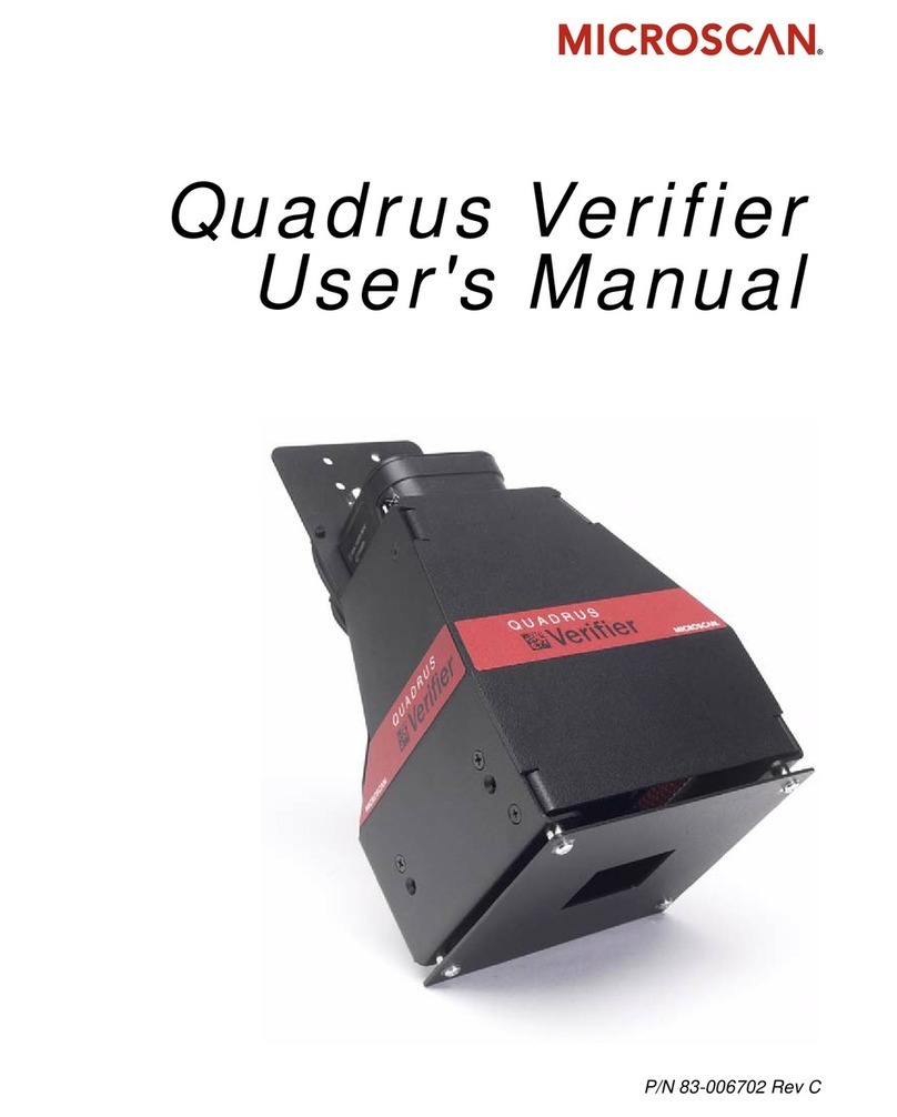
Aerotech Nmark SSaM User manual

Patent Number: US 8,426,768 B2
Revision: 2.06.00
Nmark SSaM Hardware Manual

Global Technical Support
Go to www.aerotech.com/global-technical-support for information and support about your Aerotech products. To get help
immediately, contact a service office or your sales representative (Support@aerotech.com). Include your customer order
number in your email.
Software Support:Aerotech offers a range of software packages readily available for download. Free software is available
for instant download. Chargeable software requires a current software key. Link:Software Downloads
Software Activation:The following link provides information and resources to activate your Aerotech software.
Link:Software Activation
Manuals, Help Files, and Cable Drawings:Browse a directory of manuals, help files, and cable drawings for Aerotech
software and hardware products. Link:Browse Manuals, Help Files, and Cable Drawings
Frequently Asked Questions: The Frequently Asked Questions (FAQs) section provides answers to most common
questions about Aerotech products. Link: Product FAQs
Product Training: View training information and schedule a training class. Link: Training Sessions
Request Product Repair or Return: We offer complete service and repair services for all of our products. Learn more about
our pricing and warranties, plus access the forms required for many Global Technical Support port requests. Link:Repair &
Return
Remote and Field Service Technical Support:Schedule a remote session now or a field service
appointment.Link:Remote Technical Support
This manual contains proprietary information and may not be reproduced, disclosed, or used in whole or in part without the
express written permission of Aerotech, Inc. Product names mentioned herein are used for identification purposes only and
may be trademarks of their respective companies.
Copyright © 2008-2021, Aerotech, Inc., All rights reserved.

Nmark SSaM Hardware Manual Table of Contents
Table of Contents
NmarkSSaM Hardware Manual 1
Table of Contents 3
List of Figures 4
List of Tables 5
EU Declaration of Conformity 7
Agency Approvals 8
Safety Procedures and Warnings 9
Quick Installation Guide 11
Chapter 1: Introduction 13
1.1. Electrical Specifications 16
1.2. Mechanical Design 17
1.3. Environmental Specifications 18
1.4. Drive and Software Compatibility 19
Chapter 2: Installation and Configuration 21
2.1. Communication Channel Settings 21
2.2. Power Connections 22
2.2.1. Control Supply Connections (TB109) 22
2.2.2. Minimizing ConductedRadiated and System Noise 23
2.3. FireWire Interface 24
2.4. Laser Interface (TB102) 25
2.4.1. Emergency Stop Sense Input (TB102) 29
2.5. XY2-100 Interface (J104) 30
2.6. Digital Outputs (TB101 A) 31
2.7. Digital Inputs (TB101 B) 34
2.8. Analog I/O Interface (TB103 A/B) 37
2.8.1. Analog Outputs (TB103 B) 38
2.8.2. Differential Analog Inputs (TB103 A/B) 39
2.9. Digital I/O Connector Interface (TB107 A/B) 40
2.10. Encoder Interface (TB108) 42
2.11. Switch S1 (Laser Output Polarity/Configuration) 44
2.12. Switch S2 (Axis Enable Polarity) 45
2.13. PC Configuration and Operation Information 46
Chapter 3: Maintenance 47
3.1. Test Points 48
3.2. Board Assembly 49
3.3. Preventative Maintenance 51
Appendix A: Warranty and Field Service 53
Appendix B: Revision History 55
Index 57
www.aerotech.com 3

Table of Contents Nmark SSaM Hardware Manual
List of Figures
Figure 1-1: NmarkSSaM Networked Digital Galvo Controller 13
Figure 1-2: Functional Diagram 15
Figure 1-3: Dimensions 17
Figure 2-1: Control Supply Connections 22
Figure 2-2: Laser Interface Outputs (TB102) 26
Figure 2-3: Current Sinking Configuration (with Isolation) 27
Figure 2-4: Current Sinking Configuration (without Isolation) 27
Figure 2-5: Current Sourcing Configuration (with Isolation) 28
Figure 2-6: Current Sourcing Configuration (without Isolation) 28
Figure 2-7: ESTOP Sense Input (TB102) 29
Figure 2-8: Digital Outputs (TB101 A) 32
Figure 2-9: Outputs Connected in Current Sourcing Mode 33
Figure 2-10: Outputs Connected in Current Sinking Mode 33
Figure 2-11: Digital Inputs (TB101 B) 35
Figure 2-12: Inputs Connected to a Current Sourcing Device 36
Figure 2-13: Inputs Connected to a Current Sinking Device 36
Figure 2-14: Analog Outputs (TB103 B) 38
Figure 2-15: Analog Inputs (TB103) 39
Figure 2-16: Digital Inputs (TB107) 41
Figure 2-17: Digital Outputs (TB107) 41
Figure 2-18: Encoder Connections (TB108 A/B) 43
Figure 2-19: Switch S1 (Laser Output Polarity/Configuration) 44
Figure 2-20: Switch S2 (Axis Enable Polarity) 45
Figure 3-1: Control Board Assembly 49
4 www.aerotech.com

Nmark SSaM Hardware Manual Table of Contents
List of Tables
Table 1-1: FeatureSummary 14
Table 1-2: Electrical Specifications 16
Table 1-3: Unit Weight 17
Table 1-4: Drive and Software Compatibility 19
Table 2-1: Device Number Switch Settings (S2) 21
Table 2-2: Control Supply Input Wiring (TB109) 22
Table 2-3: Control Supply Mating Connector (TB109) 22
Table 2-4: FireWire Card Part Numbers 24
Table 2-5: FireWire Repeaters (for cables exceeding 4.5 m (15 ft) specification) 24
Table 2-6: FireWire Cables (copper and glass fiber) 24
Table 2-7: Laser Interface Pinout (TB102 A) 25
Table 2-8: Laser Interface Pinout (TB102 B) 25
Table 2-9: Mating Connector Part Numbers for the Laser Interface Connector (TB102) 25
Table 2-10: Output Specifications (TB102) 26
Table 2-11: TB102BESTOPPinout 29
Table 2-12: Electrical Noise Suppression Devices 29
Table 2-13: XY2-100 Interface Connector Pinout (J104) 30
Table 2-14: Mating Connector Part Numbers for the XY2-100 Interface Connector (J104) 30
Table 2-15: Digital Outputs Pinout (TB101 A) 31
Table 2-16: Mating Connector Part Numbers for the Digital Output Connector (TB101 A/B) 31
Table 2-17: Digital Output Specifications (TB101) 31
Table 2-18: Digital Input Specifications 34
Table 2-19: Digital Inputs Pinout (TB101 B) 34
Table 2-20: Mating Connector Part Numbers for the Digital I/O Connector (TB101 A/B) 34
Table 2-21: Analog I/O Pinout (TB103 A) 37
Table 2-22: Analog I/O Pinout (TB103 B) 37
Table 2-23: Mating Connector Part Numbers for the Analog I/O Connector (TB103 A/B) 37
Table 2-24: Analog Output Specifications (TB103 B) 38
Table 2-25: Differential Analog Input Specifications (TB103 A/B) 39
Table 2-26: Digital Input Specifications (TB107) 40
Table 2-27: Digital Output Specifications (TB107) 40
Table 2-28: Digital I/O Pinout (TB107 A) 40
Table 2-29: Digital I/O Pinout (TB107 B) 40
Table 2-30: Mating Connector Part Numbers for the Digital I/O Connector (TB107 A/B) 40
Table 2-31: Encoder Input Specifications (TB108) 42
Table 2-32: Axis 1 Encoder Interface Pinout (TB108A) 42
Table 2-33: Axis 2 Encoder Interface Pinout (TB108B) 42
Table 2-34: Mating Connector Part Numbers for the Encoder Connector (TB108 A/B) 42
Table 2-35: Nmark SSaM to Drive Cable Part Numbers 42
Table 3-1: Troubleshooting 47
Table 3-2: Control Board Test Points 48
Table 3-3: Control Board Jumper Selections 50
Table 3-4: Control Board Fuse Specifications 50
Table 3-5: Preventative Maintenance 51
www.aerotech.com 5

Table of Contents Nmark SSaM Hardware Manual
6 www.aerotech.com
This page intentionally left blank.

Nmark SSaM Hardware Manual Declaration of Conformity
EU Declaration of Conformity
Manufacturer
Aerotech, Inc.
Address
101 Zeta Drive
Pittsburgh, PA 15238-2811
USA
Product
Nmark SSaM
Model/Types
All
This is to certify that the aforementioned product is in accordance with the applicable requirements of the
following Directive(s):
2014/35/EU Low Voltage Directive
EU 2015/863 Directive, Restricted Substances (RoHS3)
and has been designed to be in conformity with the applicable requirements of the following Standard(s)
when installed and used in accordance with the manufacturer’s supplied installation instructions.
EN 61010-1:2010 Safety Requirements for Electrical Equipment
Authorized Representative:
Simon Smith, European Director
Address:
Aerotech Ltd
The Old Brick Kiln, Ramsdell, Tadley
Hampshire RG26 5PR
UK
Name
/ Alex Weibel
Position
Engineer Verifying Compliance
Location
Pittsburgh, PA
Date
1/5/2021
www.aerotech.com 7

Declaration of Conformity Nmark SSaM Hardware Manual
Agency Approvals
Aerotech, Inc. Model Nmark SSaM drives have been tested and found to be in accordance to the following
listed Agency Approvals:
Approval / Certification: CUS NRTL
Approving Agency: TUV SUD America Inc.
Certificate #: U8 16 06 68995 021
Standards: CAN/CSA-C22.2 No. 61010-1:2012; UL 61010-1:2012;
EN 61010-1:2010
Visit https://www.tuev-sued.de/product-testing/certificates to view Aerotech's TÜV SÜD certificates. Type
the certificate number listed above in the search bar or type "Aerotech" for a list of all Aerotech certificates.
8 www.aerotech.com

Electrical Safety Nmark SSaM Hardware Manual
Safety Procedures and Warnings
This manual tells you how to carefully and correctly use and operate the Nmark SSaM.
lRead all parts of this manual before you install or operate the Nmark SSaM or before you
do maintenance to your system.
lTo prevent injury to you and damage to the equipment, obey the precautions in this
manual.
lAerotech continually improves its product offerings; listed options may be superseded at
any time. All drawings and illustrations are for reference only and were complete and
accurate as of this manual’s release. Refer to www.aerotech.com for the most up-to-date
information.
If you do not understand the information in this manual, contact Aerotech Global Technical
Support.
This product has been designed for light industrial manufacturing or laboratory environments. The protection
provided by the equipment could be impaired if the product is used in a manner not specified by the
manufacturer.
D A N G E R : This product contains potentially lethal voltages. To reduce the possibility of
electrical shock, bodily injury, or death the following precautions must be followed.
1. Disconnect electrical power before servicing equipment.
2. Disconnect electrical power before performing any wiring.
3. Access to the Nmark SSaM and component parts must be restricted while connected to a
power source.
4. To minimize the possibility of electrical shock and bodily injury, extreme care must be
exercised when any electrical circuits are in use. Suitable precautions and protection must
be provided to warn and prevent persons from making contact with live circuits.
5. Install the Nmark SSaM inside a rack or enclosure.
6. Refer to local electrical safety requirements to correctly size external system wires.
7. Do not connect or disconnect any electrical components or connecting cables while
connected to a power source.
8. All components must be properly grounded in accordance with local electrical safety
requirements.
9. Operator safeguarding requirements must be addressed during final integration of the
product.
W A R N I N G : To minimize the possibility of electrical shock, bodily injury or death the
following precautions must be followed.
1. If the product is used in a manner not specified by the manufacturer, the protection
provided by the product can be impaired and result in damage, shock, injury, or death.
2. Moving parts can cause crushing or shearing injuries. Access to all stage and motor parts
must be restricted while connected to a power source.
3. Cables can pose a tripping hazard. Securely mount and position all system cables to avoid
potential hazards.
4. Do not expose this product to environments or conditions outside of the listed
specifications. Exceeding environmental or operating specifications can cause damage to
the equipment.
5. Operators must be trained before operating this equipment.
6. All service and maintenance must be performed by qualified personnel.
www.aerotech.com 9

Nmark SSaM Hardware Manual Electrical Safety
10 www.aerotech.com
This page intentionally left blank.

Nmark SSaM Hardware Manual Quick Installation Guide
Quick Installation Guide
This chapter describes the order in which connections and settings should typically be made to the
Nmark SSaM. If a custom interconnection drawing was created for your system (look for a line item on your
Sales Order under the heading “Integration”), that drawing can be found on your installation device.
Device Number Section 2.1. Communication Channel Settings
FireWire Section 2.3. FireWire Interface
Laser Interface Input Section 2.4. Laser Interface (TB102)
XY2-100 Interface Section 2.5. XY2-100 Interface (J104)
Control Supply Section 2.2.1. Control Supply Connections (TB109)
www.aerotech.com 11

Quick Installation Guide Nmark SSaM Hardware Manual
12 www.aerotech.com
This page intentionally left blank.

Nmark SSaM Hardware Manual Introduction
Chapter 1: Introduction
Aerotech’s Nmark SSaM, part of the A3200 product family, is a galvo scanner control module that
synchronizes galvo and servo motion, expanding the scanner’s field of view and broadening its application
base while maintaining the high throughput capabilities expected from scanners.
Figure 1-1: Nmark SSaM Networked Digital Galvo Controller
www.aerotech.com Chapter 1 13

Introduction Nmark SSaM Hardware Manual
Table 1-1: FeatureSummary
Standard Features
lSupports 2 axis Galvo controllers via XY2-100 interface
lTwo auxiliary channels of 40 MHz line driver quadrature encoder inputs.
lEight optically-isolated digital inputs; 5-24V
lEight optically-isolated digital outputs sinking or sourcing; 5-24V
lFour 16-bit differential analog inputs
lThree 16-bit analog outputs
lEight digital inputs
lTwo digital outputs
lThree FireWire ports
lThree optically isolated Laser Outputs
lThree differential Laser Outputs
lDedicated 5-24V Emergency Stop sense input
lInternal power supply
l5 VDC, 500 mA user output power for encoder
Options
-SRC Configure laser outputs as sourcing outputs (default is sinking)
-SINK Configure laser outputs as sinking outputs (factory configuration, jumper
settings cannot be changed in the field)
-3AX Three axis version
14 Chapter 1 www.aerotech.com

Introduction Nmark SSaM Hardware Manual
1.1. Electrical Specifications
The electrical specifications for the Nmark SSaM are listed below.
Table 1-2: Electrical Specifications
Description Nmark SSaM
Control Supply
Input Voltage 85-240 VAC
Input Frequency 50-60 Hz
Inrush Current 16 A (peak)
Input Current 0.15A(max)
Mode of Operation Galvo
16 Chapter 1 www.aerotech.com

Nmark SSaM Hardware Manual Introduction
1.2. Mechanical Design
The following figure shows the Nmark SSaM package dimension as well as the typical mounting orientation.
Figure 1-3: Dimensions
Table 1-3: Unit Weight
Weight
1.0 kg [2.2 lb]
www.aerotech.com Chapter 1 17

Introduction Nmark SSaM Hardware Manual
1.3. Environmental Specifications
The environmental specifications for the Nmark SSaM are listed below.
Ambient Temperature Operating: 0° to 50°C (32° to 122° F)
Storage: -30° to 85°C (-22° to 185° F)
Humidity Maximum relative humidity is 80% for temperatures up to 31°C.
Decreasing linearly to 50% relative humidity at 40°C. Non condensing.
Altitude
Operating: 0 m to 2,000 m (0 ft to 6,562 ft) above sea level
Contact Aerotech if your specific application involves use above 2,000 m
or below sea level.
Pollution Pollution degree 2 (normally only non-conductive pollution).
Use Indoor use only
18 Chapter 1 www.aerotech.com

Nmark SSaM Hardware Manual Introduction
1.4. Drive and Software Compatibility
The following table lists the available drives and which version of the software first supported the drive.
Drives that list a specific version number in the Last Software Version column will not be supported after
the listed version.
Table 1-4: Drive and Software Compatibility
Drive Type Firmware Revision First Software Version Last Software Version
Nmark SSaM - 2.21 Current
A 4.06.001 Current
www.aerotech.com Chapter 1 19

Introduction Nmark SSaM Hardware Manual
20 Chapter 1 www.aerotech.com
This page intentionally left blank.
Table of contents