manuals.online logo
Brands
  1. Home
  2. •
  3. Brands
  4. •
  5. AES global
  6. •
  7. Intercom System
  8. •
  9. AES global Imperial 703 DECT User manual

AES global Imperial 703 DECT User manual

Button 1
Button 2
Button 3 Button 4
C
C
C
C
+-
+24V-
+-
101
220
RELAY 2
RELAY 1
1
2
3
4
C
12V
OUT
24V
AC DC
IN
RELAY
1
RELAY
2
+
-
N/C | C | N/O
N/O | C | N/C
= COMMON
N/O
C
N/C
Link both Relay 1’s to
allow either to release the
same door / gate.
N/C | C | N/ON/O | C | N/ C
SITE SURVEY
OPTIMAL RANGE
WIRING DIAGRAM
TIP: For longer range installations, locate the handset closest to the front of the
property and near a window if possible. Also ensure the transmitter is mounted
pointing towards the handset.
Concrete walls can reduce the normal open-air range of up to 400 metres/yards
by 30-50% per wall.
TIP: Most technical calls received are due to installers using CAT5 or alarm cable
to power the unit.
NEITHER are rated to carry enough power! ( 1.2amp peak )
Please use the following cable:
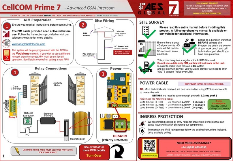
Up to 2 metres ( 6 feet ) –Use minimum 0.5mm2( 18 gauge )
Up to 4 metres ( 12 feet ) –Use minimum 0.75mm2 ( 16 gauge )
Up to 8 metres ( 24 feet ) –Use minimum 1.0mm2( 14 / 16 gauge )
POWER CABLE
Shield/Filter
Drain Cable
Insert Drain Cable into
0v (-) on Power IN
Code
Button
Optional
Antenna
Pairing
LEDs
Normally Open
Common
Normally Closed
RELAY CONNECTIONS
RELAY 1
RELAY 1
Transmitter Module
WARNING:
ESD SENSITIVE
To Gate Controller
24V AES Power Supply
* ALWAYS RANGE TEST THE UNIT ON SITE BEFORE INSTALLATION *
MAX 24 VOLTS!
POWER ADAPTER
MAINS
POWER
MAGNETIC LOCK
MAGNETIC LOCK EXAMPLE
TRANSMITTER AES KEYPAD
+
-
-
+* MAGNETIC LOCK PSU SOLD SEPARATELY *
Follow this method when using a magnetic lock. If the relay in either the
Transmitter or optional AES Keypad is triggered it will temporarily lose power
and allow the door/gate to release.
For installs without the optional AES Keypad; connect the POSITIVE of the
Magnetic Lock PSU to N/C terminal on Transmitter Relay.
NEED MORE ASSISTANCE?
Please scan this QR Code to be
brought to our Resources page
where you can find all of our
guides and available resources.
EXIT
SUFFICIENT POWER CABLE FOR
CALLPOINT REQUIRED ( 2x1mm2 )
LIGHTNING PRONE AREAS
MUST USE SURGE PROTECTION
FOR POWER SUPPLY!
703 DECT - Imperial Intercom System STILL HAVING TROUBLE?
Find all of our support options such as Web Chat,
Full Manuals, Customer Helpline and more on
our website:
WWW.AESGLOBALONLINE.COM
SYSTEM INCOMPATIBLE WITH FOIL INSULATION.
KEEP POWER SUPPLY AS CLOSE AS POSSIBLE.
KEEP SHORT
( 8m MAX! )
RESTOCKING FEES MAY APPLY IF RETURNED AFTER INSTALL DUE TO SITE
ISSUES. PLEASE SEE FULL T&C’S ON OUR WEBSITE.
COM
COM
BUTTON 3
BUTTON 2
BUTTON 1
BUTTON 4
NOTE: Wiring method will
change dependingon
amount of buttons on
faceplate.
See provided supplement guide for
more info.
RELAY 1 R2
24v IN
THE AES KEYPAD IS AN OPTIONAL EXTRA.
IF KEYPAD PRESENT, PLEASE SEE ‘KPX1200 GUIDE’
FOR FULL INSTRUCTIONS ON PROGRAMMING AND
EXTENSIVE FEATURES.
Optional Programmable Keypad
RELAY 1 R2
12.000
24v IN EGRESS
RELAY 3
GROUND
+ - N.C. COM N.O. N.C. / N.O.
DATA
I/O
EG
IN
N.C. COM N.O. Ko r A
O/P
DU
OUT
DOOR
SENS
(-)
GND
O/P 1
INHIB.
INT
LOCK
TAMPER
N.C.
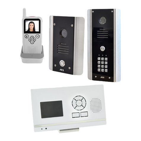
With our 703 DECT audio system you can
add up to a max of 4 portable handsets or
wall mounted versions.
(1 DEVICE WILL RING PER BUTTON)
Did you know?
AES KP will come pre-
wired to the CallPoint TIP: It is recommended that the system be fully tested on site BEFORE installation.
You must test to ensure that the system is capable of operating across the desired
range. Power the system on and place the handsets in their expected locations
around the property to ensure that the system is fully functional and suitable for
the site.
The handset should ideally be charged for at least 8 hours before use. It is recommended to give it at least 60 minutes of charge
before performing the range test between the transmitter module and the handset inside.
N/C | C | N/O
N/O | C | N/C
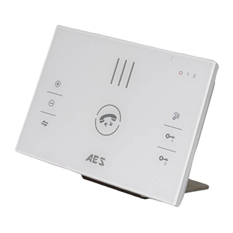
Wall/Desk Mounted Audio Panel (603 / 703 / 705)
RE-CODING/ADDING EXTRA HANDSETS
INFORMATION ABOUT YOUR DECT HANDSET
* ALWAYS RANGE TEST THE UNIT ON SITE BEFORE INSTALLATION *
STRIKE
LOCK
AC/DC STRIKE LOCK
WIRING EXAMPLE
Follow this method when using a Strike Lock with
the system. If used it will mean that if a relay in
either the Transmitter or optional AES Keypad is
triggered it will temporarily allow the door/gate
to release.
MAX 24 VOLTS!
POWER ADAPTER
MAINS
POWER
+
-
TRANSMITTER
AES KEYPAD
* STRIKE LOCK PSU SOLD SEPARATELY *
Do you require a custom wiring diagram for your site? Please send all
requests to d[email protected] and we will do our best
to provide you with a supplement diagram suitable for your chosen
equipment.
We are constantly using your customer feedback to enhance all of
our guides / learning material for installers.
If you have any suggestions regardingthis please send any
suggestions to [email protected]
703 DECT - Imperial Intercom System STILL HAVING TROUBLE?
Find all of our support options such as Web Chat,
Full Manuals, Customer Helpline and more on
our website:
WWW.AESGLOBALONLINE.COM
Occasionally the system may need to be re-coded once installed.
If the handset does not ring when the call button is pressed,
the system may need to be re-coded.
( ●= FULL RE-CODE : STEP 1-5 )
(●= ADDING A HANDSET : STEP 3-5 )
●Step 1) Press and hold the CODE BUTTON inside the Transmitter Module for 5 seconds
until the audible tone is heard from the Intercom speaker.
●Step 2) Then press the CODE BUTTON 14 times and wait until the melody is heard or the
LED turns off. Performing this step will remove ALL handsets currently synced (or partially
synced) to the system.
●●Step 3) Press and hold the CODE BUTTON inside the Transmitter Module for 5 seconds
until the blue pairing LED marked as D17 begins to flash.
●●Step 4) Then press and hold the CODE BUTTON on the handset until the red LED at the
top begins to flash. After a few seconds you will hear a melody play to let you know it has
successfully connected.
●●Step 5) Finally you should test the kit to ensure that everything is working as expected
by pressing the Call Button on the CallPoint to ensure the handset and/or wall mounted unit
receives the call and that the two way speech is functioning correctly.
( On 703 Transmitter the blue LED marked D17 should also flash. )
( Note: Doing this step will also clear ALL voicemails after reset. )
( An audible tone will be heard from the Intercom Speaker. )
( Repeat Steps 3 & 4 for each new handset. )
OK
TI:ME
Example shows the
location of the CODE
BUTTON that can be
found on the back of
the wall mounted unit.
CODE BUTTON
Can be found on
reverse side.
+24V-
+-
101
220
RELAY 2
RELAY 1
12.000
1
2
3
4
C
12V
OUT
24V
AC DC
IN
RELAY
1
RELAY
2
+
-
N/C | C | N/O
N/O | C | N/C
TRANSMITTER
CODE BUTTON
603/703 DECT
Handsets will be
displayed in
order of H1, H2,
H3 & H4.
TI : ME
OK
ON/OFF VIBRATE
ON/OFF
RECEPTION
INDICATOR
BATTERY
LEVEL
VOICEMAIL
SYMBOL
PAIRING
LED
RELAY 2 RELAY 1
CODE BUTTON
Adjusting the Relay trigger time
Press and hold the RELAY 2 button for 3 seconds, scroll through the menu
until you see ‘ti’.
Press the button to select the relay time. Press the key at any time to end
the process.
OK
Adjusting the time on your handset
Press and hold the button for 3 seconds, then use the up and keys to
select the hour and press button again to cycle to minutes. Once you have
finished adjusting the time then press the button to save. Press the key at
any time to end the process.
OK
OK
OK
Voicemail On/Off
You can turn the voicemail function of the system On/Off at any time. To start
press and hold the RELAY 2 button for 3 seconds then scroll through the menu
until you see ‘Re’ and adjust this to ON or OFF then press to select.
OK
To listen to a voicemail, press . If there is more than 1 use and to select the message required and press to play.
Press RELAY 1 once to delete the message or press and hold it to delete all.
OK
OK

This manual suits for next models

1

Other AES global Intercom System manuals

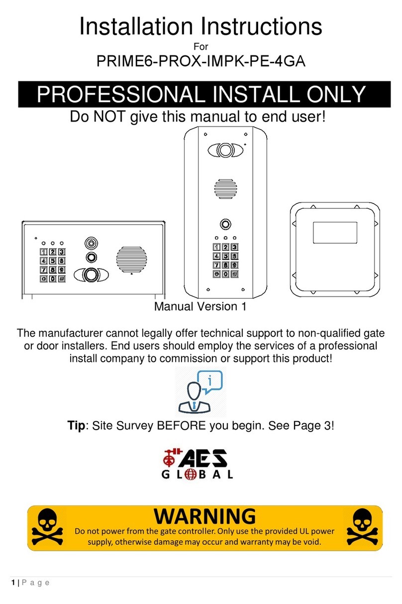
AES global PRIME6-PROX-IMPK-PE-4GA User manual

AES global

AES global PRIME6-PROX-IMPK-PE-4GA User manual

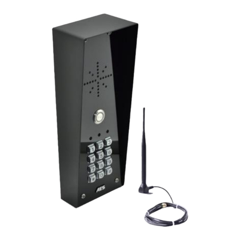
AES global Cellcom Prime 5AB User manual

AES global

AES global Cellcom Prime 5AB User manual

AES global StylusCOM Audio User manual

AES global

AES global StylusCOM Audio User manual

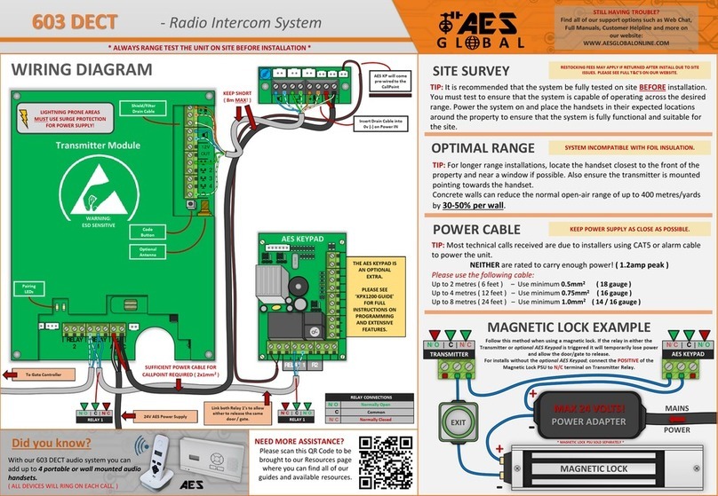
AES global 603 DECT User manual

AES global

AES global 603 DECT User manual

AES global Praetorian Guard Series Assembly Instructions

AES global

AES global Praetorian Guard Series Assembly Instructions

AES global CellCOM Prime 7 User manual

AES global

AES global CellCOM Prime 7 User manual

AES global 705 DECT User manual

AES global

AES global 705 DECT User manual

AES global CellCOM PRIME Assembly Instructions

AES global

AES global CellCOM PRIME Assembly Instructions

AES global Praetorian Guard Assembly Instructions

AES global

AES global Praetorian Guard Assembly Instructions

AES global CellCOM Prime 7 4G User manual

AES global

AES global CellCOM Prime 7 4G User manual

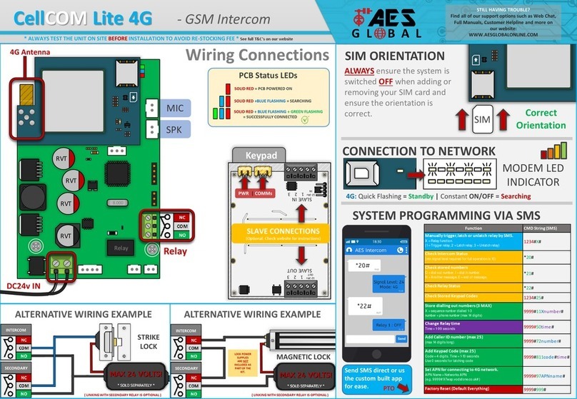
AES global CellCOM Lite 4G User manual

AES global

AES global CellCOM Lite 4G User manual

AES global StyluscomV2 Series Instruction Manual

AES global

AES global StyluscomV2 Series Instruction Manual

AES global 603 User manual

AES global

AES global 603 User manual

AES global Styluscom Video User manual

AES global

AES global Styluscom Video User manual

AES global 603 DECT User manual

AES global

AES global 603 DECT User manual

Popular Intercom System manuals by other brands

AEQ XPEAK user manual

AEQ

AEQ XPEAK user manual

Anchor PGM-2000 owner's manual

Anchor

Anchor PGM-2000 owner's manual

Partner Elite (PEKP) System installation manual

Partner

Partner Elite (PEKP) System installation manual

golmar GB2 Nexa Modular user manual

golmar

golmar GB2 Nexa Modular user manual

Akuvox IT82 Series Admin guide

Akuvox

Akuvox IT82 Series Admin guide

XtendLan DPC-D241-1 user manual

XtendLan

XtendLan DPC-D241-1 user manual

Viking Electronics E-10-IP product manual

Viking Electronics

Viking Electronics E-10-IP product manual

Studio Technologies 5421 user guide

Studio Technologies

Studio Technologies 5421 user guide

urmet domus 6025/401 quick start guide

urmet domus

urmet domus 6025/401 quick start guide

Philips WelcomeEye Comfort user manual

Philips

Philips WelcomeEye Comfort user manual

ipdoor Match Advanced IP7700 quick start

ipdoor

ipdoor Match Advanced IP7700 quick start

BASI TS710 Assembly & operating instructions

BASI

BASI TS710 Assembly & operating instructions

Fermax COLOUR VDS LOFT MEMORY MONITOR manual

Fermax

Fermax COLOUR VDS LOFT MEMORY MONITOR manual

true-i SMART HOME SYSTEM user manual

true-i

true-i SMART HOME SYSTEM user manual

Aiphone TALKMASTER IP EWST-POE Software user's guide

Aiphone

Aiphone TALKMASTER IP EWST-POE Software user's guide

Mobotix T25 Integration note

Mobotix

Mobotix T25 Integration note

Vimar ELVOX Due Fili Plus K40505G.01 Installer manual

Vimar

Vimar ELVOX Due Fili Plus K40505G.01 Installer manual

Toa N-8000DI installation manual

Toa

Toa N-8000DI installation manual

manuals.online logo
manuals.online logoBrands
  • About & Mission
  • Contact us
  • Privacy Policy
  • Terms and Conditions

Copyright 2025 Manuals.Online. All Rights Reserved.