manuals.online logo
Brands
  1. Home
  2. •
  3. Brands
  4. •
  5. AES global
  6. •
  7. Intercom System
  8. •
  9. AES global Styluscom Video User manual

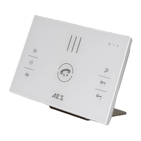
AES global Styluscom Video User manual

RELAY 1
Optional Programmable Keypad
THE AES KEYPAD IS AN OPTIONAL EXTRA.
IF KEYPAD PRESENT, PLEASE SEE THE
‘KPX1200 GUIDE’ ON OUR WEBSITE
FOR FULL INSTRUCTIONS ON PROGRAMMING
AND EXTENSIVE FEATURES.
MODEL: Stylus V2
RELAY 1 R2
12.000
24v IN EGRESS
RELAY 3
GROUND
+ - N.C. COM N.O. N.C. / N.O.
DATA
I/O
EG
IN
N.C. COM N.O. K or A
O/P
DU
OU T
DO OR
SENS
(-)
GN D
O/P 1
INH IB.
INT
LOCK
TAMPE R
N.C.
MODEL: Stylus V2
RELAY 1 R2
12.000
24v IN EGRESS
RELAY 3
GROUND
+ - N.C. COM N.O. N.C. / N.O.
DA TA
I/O
EG
IN
N.C. COM N.O. K or A
O/P
DU
OU T
DO OR
SENS
(-)
GN D
O/P 1
INH IB.
INT
LOCK
TAMPER
N.C.
N/C | C | N/ON/O | C | N/C
OPTIMAL RANGE
StylusCOM Video
STYLUSCOM - WIRING DIAGRAM
TIP: To get the most range out of the system we would recommend keeping the
separate power supply as close as possible to the video monitor. If chaining
multiple monitors together use the SLAVE inputs and outputs - see supplement
wiring diagram which will provide more information on the specific requirements
and max distances.
TIP: Most technical calls received are due to installers using CAT5 or alarm cable
to power the unit.
NEITHER are rated to carry enough power! ( 1.2amp peak )
Please use the following cable:
Up to 2 metres ( 6 feet ) –Use minimum 0.5mm2( 18 gauge )
Up to 4 metres ( 12 feet ) –Use minimum 0.75mm2 ( 16 gauge )
Up to 8 metres ( 24 feet ) –Use minimum 1.0mm2( 14 / 16 gauge )
POWER CABLE
Pairing
LEDs
- Hardwired System
MAX 24 VOLTS!
POWER ADAPTER
MAINS
POWER
MAGNETIC LOCK
MAGNETIC LOCK EXAMPLE
CALL STATION AES KEYPAD
+
-
-
+* MAGNETIC LOCK PSU SOLD SEPARATELY *
EXIT
Follow this method when using a magnetic lock. If the relay in either the
Call Station or optional AES Keypad is triggered it will temporarily lose
power and allow the door/gate to release.
For installs without the optional AES Keypad; connect the POSITIVE of the
Magnetic Lock PSU to N/C terminal on Call Station Relay.
STILL HAVING TROUBLE?
Find all of our support options such as Web Chat,
Full Manuals, Customer Helpline and more on
our website:
WWW.AESGLOBALONLINE.COM
SHIELDED CABLE IS ALWAYS RECOMMENDED
KEEP POWER SUPPLY AS CLOSE AS POSSIBLE.
SITE SURVEY
TIP: It is recommended that the system be fully tested on site BEFORE installation.
You must test to ensure that the system is capable of operating on the desired site.
Power the system on and place the monitors in their expected locations around
the property and then test that everything is working BEFORE mounting any items
to the walls.
RESTOCKING FEES MAY APPLY IF RETURNED AFTER INSTALL DUE TO SITE
ISSUES. PLEASE SEE FULL T&C’S ON OUR WEBSITE
NEED MORE ASSISTANCE?
PLEASE SCAN THIS QR CODE TO BE
BROUGHT TO OUR RESOURCES PAGE
WHERE YOU CAN FIND ALL OF OUR
GUIDES AND AVAILABLE RESOURCES.
N/O
C
N/C
Normally Open
Common
Normally Closed
RELAY CONNECTIONS
PLEASE USE ADDITIONAL POWER
SUPPLY (NOT PROVIDED) FOR
DISTANCES GREATER THAN 130m.
CHECK FURTHER INFORMATION FOR
MAX MONITOR DISTANCES AND
POWER REQUIREMENTS, OR IF YOU
NEED TO CHAIN MULTIPLE MONITORS
TOGETHER.
PLEASE USE THE 24v POWERSUPPLY
PROVIDED WITH THE STYLUSCOM KIT.
Power for keypad will come
already pre-wired.
MODEL: Stylus V2
RELAY 1 R2
12.000
24v IN EGRESS
RELAY 3
GROUND
+ - N.C. COM N.O. N.C. / N.O.
DA TA
I/O
EG
IN
N.C. COM N.O. K or A
O/P
DU
OU T
DO OR
SENS
(-)
GN D
O/P 1
INH IB.
INT
LOCK
TAMPER
N.C.
SLAVE OUT SLAVE IN
DATA
VIDEO
GND
AUDIO
DATA
VIDEO
GND
AUDIO
STATION 2 STATION 1
VID1+
VID1-
AUD1
GND
CMD1
VID1+
VID1-
AUD1
GND
CMD1
0v
24v
300m MAX
DISTANCE
(SHIELDED CAT5)
24v
0v
CMD
AUD
GND
N/C
COM
N/O
N/C
COM
N/O
RELAY 2
RELAY 1
* ALWAYS FULLY TEST THE UNIT ON SITE BEFORE INSTALLATION TO AVOID RESTOCKING FEES *
CONNECTIONS WILL GO TO GATE
CONTROLLER/DOOR LOCK ETC.
PLEASE SEE ADDITIONAL DIAGRAMS
FOR RELAY CONNECTIONS FOR THE
REQUIRED TYTPE.
(300m MAX DISTANCE)
VID-
VID+
N/C | C | N/O
N/O | C | N/C
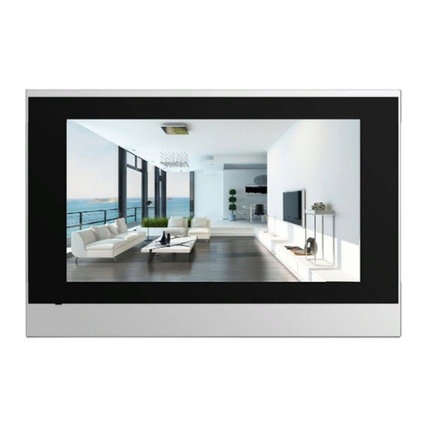
HOW TO USE THE STYLUSCOM MONITOR
INFORMATION ABOUT YOUR VIDEO MONITOR
STRIKE
LOCK
AC/DC STRIKE LOCK
WIRING EXAMPLE
Follow this method when using a Strike Lock with
the system. If used it will mean that if a relay in
either the Call Station or optional AES Keypad is
triggered it will temporarily allow the door/gate
to release.
MAX 24 VOLTS!
POWER ADAPTER
MAINS
POWER
+
-
CALL STATION
AES KEYPAD
* STRIKE LOCK PSU SOLD SEPARATELY *
Do you require a custom wiring diagram for your site? Please send all
requests to diagrams@aesglobalonline.com and we will do our best
to provide you with a supplement diagram suitable for your chosen
equipment.
We are constantly using your customer feedback to enhance all of
our guides / learning material for installers.
If you have any suggestions regardingthis please send any
suggestions to feedb[email protected]
STILL HAVING TROUBLE?
Find all of our support options such as Web Chat,
Full Manuals, Customer Helpline and more on
our website:
WWW.AESGLOBALONLINE.COM
INCREASE IN CALL VOLUME
DECREASE IN CALL VOLUME
TRANSFER THE CALL
MONITORING MODE
ACTIVATE RELAY 1
ACTIVATE RELAY 2
1
2
ANSWER CALL BUTTON
180mm
130mm
Front depth
Tap to answer incoming call.
Tap to increase volume of monitor.
Tap to decrease volume of monitor.
Tap to transfer the call to other monitor(s).
Tap to listen to the intercom microphone.
Tap to activate Relay 1.
Tap to activate Relay 2.
16mm
CUT DIMENSIONS
165mm
115mm
9mm
25mm
Rear depth
Total depth
* ALWAYS FULLY TEST THE UNIT ON SITE BEFORE INSTALLATION TO AVOID RESTOCKING FEES *
(tap again to hang up call)
StylusCOM Video - Hardwired System
TOP
S
I
D
E
FRONT
MONITORING MODE
Tap to monitor the intercom video & audio.
StylusCOM Monitor
TOP
S
I
D
E
FRONT
MAX
DISTANCES
Call Station
See ‘POWER CABLE’ section on Quick
Start Guide for power supply
requirements for Call Station power
supply.
1x 2x Dual Power Supply :
CAT5 Cable –300m
Poly/Poly Underground –150m
Multi pair telephone wire –50m
TIP:
To achieve greater distances shown in ‘2x
Dual Power Supply’ a separate power
supply is required (sold separately).
Single Power Supply :
CAT5 Cable –130m
Poly/Poly Underground –30m
Multi pair telephone wire –30m
StylusCOM –Power Options
MASTER
SLAVE
SLAVE
24v
0v
24v
0v
24v
0v
StylusCOM –Slave Monitor Wiring Guide
MASTER
SLAVE
SLAVE
PSU #2
Wire the SLAVE OUT terminals to the SLAVE IN
terminals of the next monitor.
SLAVE OUT can also be split 2-ways as shown
in the diagram below.
TO MONITOR 4
4MONITORS
IN TOTAL :
1MASTER
3SLAVES
KEEP POWER CABLE BETWEEN MONITORS AS SHORT AS POSSIBLE –SEE POWER CABLE ON PAGE 1
Monitor Power Supply Distances:
CAT5 Cable –8m
1.5mm Cable –15m
(MAX DISTANCE BETWEEN MONITORS)
(THE MASTER MONITOR MUST ALREADY BE SET UP BEFORE TESTING SLAVES)
SLAVE OUT SLAVE IN
DATA
VIDEO
GND
AUDIO
DATA
VIDEO
GND
AUDIO
SLAVE OUT SLAVE IN
DATA
VIDEO
GND
AUDIO
DATA
VIDEO
GND
AUDIO
SLAVE OUT SLAVE IN
DATA
VIDEO
GND
AUDIO
DATA
VIDEO
GND
AUDIO
PSU #2
1.5mm POWER CABLE
RECCOMENDED
BETWEEN EACH
MONITOR
Second power supply is used to power all
of the monitors indoors. Power between
monitors will be shared using 1.0mm
cable.
MONITOR 4

Other AES global Intercom System manuals

AES global 603 User manual

AES global

AES global 603 User manual

AES global CellCOM PRIME Assembly Instructions

AES global

AES global CellCOM PRIME Assembly Instructions

AES global Praetorian Guard Series Assembly Instructions

AES global

AES global Praetorian Guard Series Assembly Instructions

AES global CellCOM Prime 7 4G User manual

AES global

AES global CellCOM Prime 7 4G User manual

AES global CellCOM Prime 7 User manual

AES global

AES global CellCOM Prime 7 User manual

AES global Praetorian Guard Assembly Instructions

AES global

AES global Praetorian Guard Assembly Instructions

AES global Cellcom Prime 5AB User manual

AES global

AES global Cellcom Prime 5AB User manual

AES global StyluscomV2 Series Instruction Manual

AES global

AES global StyluscomV2 Series Instruction Manual

AES global Imperial 703 DECT User manual

AES global

AES global Imperial 703 DECT User manual

AES global StylusCOM Audio User manual

AES global

AES global StylusCOM Audio User manual

AES global 603 DECT User manual

AES global

AES global 603 DECT User manual

AES global CellCOM Lite 4G User manual

AES global

AES global CellCOM Lite 4G User manual

AES global PRIME6-PROX-IMPK-PE-4GA User manual

AES global

AES global PRIME6-PROX-IMPK-PE-4GA User manual

AES global 603 DECT User manual

AES global

AES global 603 DECT User manual

AES global 705 DECT User manual

AES global

AES global 705 DECT User manual

Popular Intercom System manuals by other brands

Comelit 3451S Technical manual

Comelit

Comelit 3451S Technical manual

Mircom RAM-216 Wiring & installation manual

Mircom

Mircom RAM-216 Wiring & installation manual

Paxton Net2 Entry quick start guide

Paxton

Paxton Net2 Entry quick start guide

urmet domus VOG 7 1760 Quick user guide

urmet domus

urmet domus VOG 7 1760 Quick user guide

Telex RadioCom BTR-700 supplementary guide

Telex

Telex RadioCom BTR-700 supplementary guide

golmar G2+ user manual

golmar

golmar G2+ user manual

Fermax LYNX SKYLINE Installer manual

Fermax

Fermax LYNX SKYLINE Installer manual

Commax CMP-2BA user manual

Commax

Commax CMP-2BA user manual

2easy DMR21 installation guide

2easy

2easy DMR21 installation guide

Me VDV-510.1 operating instructions

Me

Me VDV-510.1 operating instructions

Videx Door Intercom System Technical manual

Videx

Videx Door Intercom System Technical manual

Fermax 2235 quick start guide

Fermax

Fermax 2235 quick start guide

Midland BT1 Instruction guide

Midland

Midland BT1 Instruction guide

Zartek CDP-808 Troubleshooting

Zartek

Zartek CDP-808 Troubleshooting

Defiant 18000019 Use and care guide

Defiant

Defiant 18000019 Use and care guide

SSS Siedle BFC 850-0 operating instructions

SSS Siedle

SSS Siedle BFC 850-0 operating instructions

Alpha Communications ALPHA-PAGE v4.0 Installation & owner's manual

Alpha Communications

Alpha Communications ALPHA-PAGE v4.0 Installation & owner's manual

Fermax DUOX PLUS VEO MONITOR quick start guide

Fermax

Fermax DUOX PLUS VEO MONITOR quick start guide

manuals.online logo
manuals.online logoBrands
  • About & Mission
  • Contact us
  • Privacy Policy
  • Terms and Conditions

Copyright 2025 Manuals.Online. All Rights Reserved.