Tunstall Communicall Vi IP User manual

D9507043B1
Communicall
Vi IP
Manager User Guide

D9507043B1
Contents
1. Introduction ......................................................................................................................................................... 3
2. Main System Components ................................................................................................................................. 4
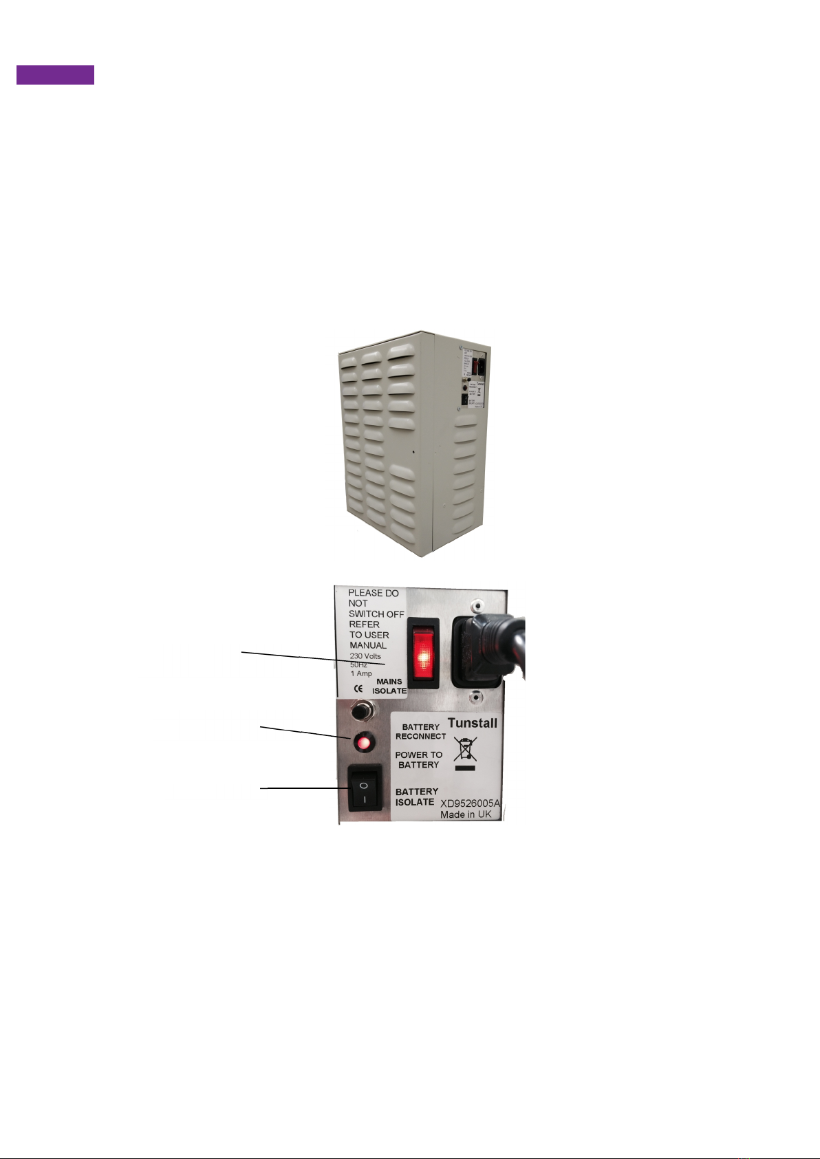
Control Unit ................................................................................................................................................................ 4
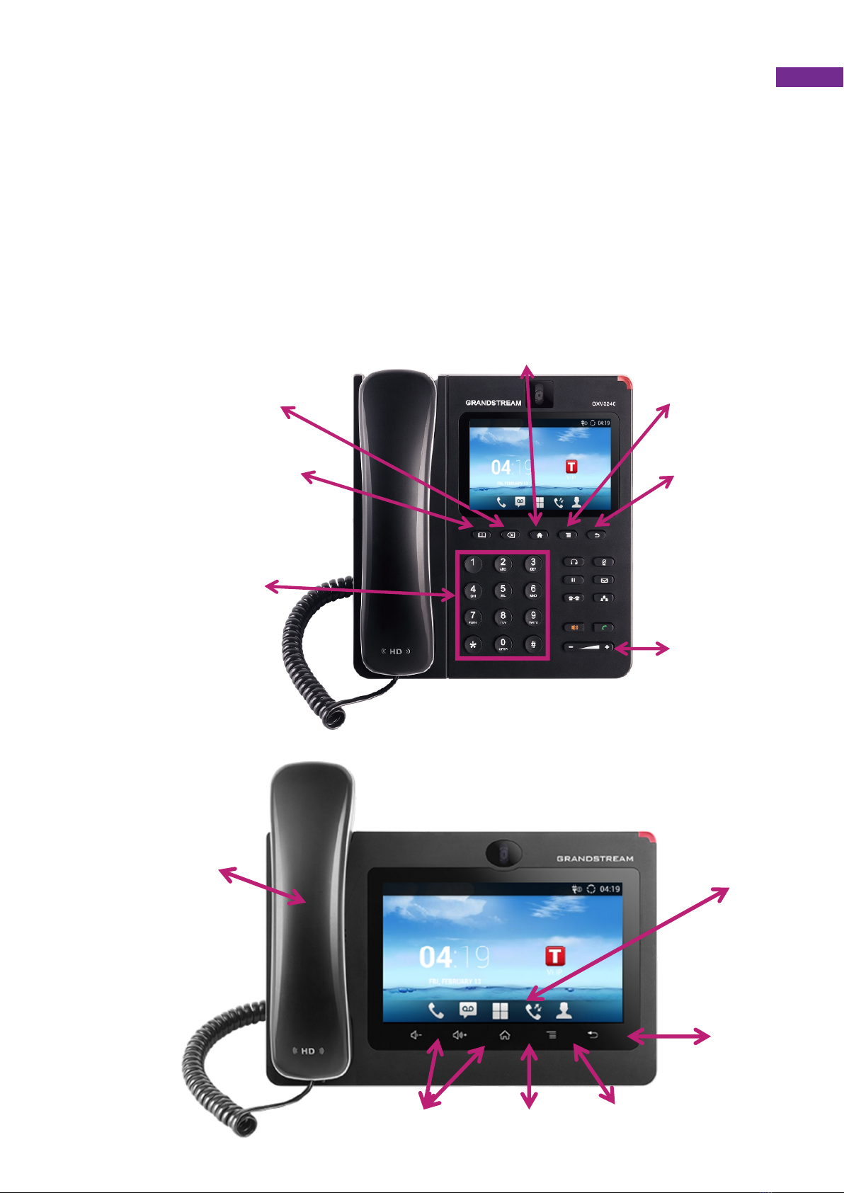
IP Room Unit .............................................................................................................................................................. 5
Speech Modules ........................................................................................................................................................ 6
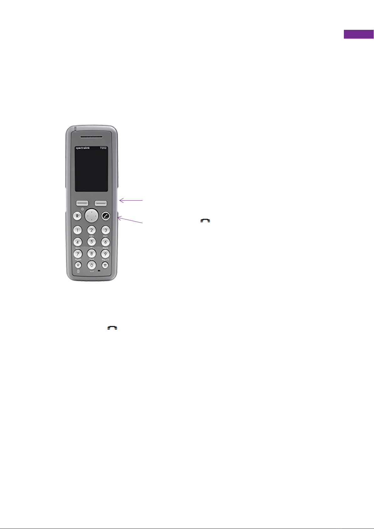
DECT Handsets ......................................................................................................................................................... 7
3. System Operation ............................................................................................................................................... 8
Quick Start Guide ....................................................................................................................................................... 8
System Control Panel (SCP) ................................................................................................................................... 10
Standby and Initial Screens ....................................................................................................................................................... 10
Change Site Status .................................................................................................................................................................... 10
Main Menu................................................................................................................................................................................. 11
Call Menu .................................................................................................................................................................................. 11
Trigger Menu ............................................................................................................................................................................. 12
Settings Menu ........................................................................................................................................................................... 14
Advanced Menu ........................................................................................................................................................................ 15
Access Fobs .............................................................................................................................................................................. 16
Web Browser ........................................................................................................................................................... 19
Login ......................................................................................................................................................................................... 19
Navigation ................................................................................................................................................................................. 19
Users ......................................................................................................................................................................................... 21
Residents .................................................................................................................................................................................. 21
Inactivity Feature ....................................................................................................................................................................... 22
Activity Monitor .......................................................................................................................................................................... 22
Allow Calls from Door Panel (s) ................................................................................................................................................. 24
Radio Triggers ........................................................................................................................................................................... 25
Advanced Speech Module Settings ........................................................................................................................................... 25
Control Centres ......................................................................................................................................................................... 26
Quick Dials ................................................................................................................................................................................ 26
Tradesmen ................................................................................................................................................................................ 27
4. System Information ................................................................................................................................................ 28
Access Group Log ................................................................................................................................................... 28
Resident Information ................................................................................................................................................ 28

3
1. Introduction
Communicall Vi IP is the latest generation communication system for grouped housing
developments. It supports individually tailored telecare for residents and provides highly
flexible call routing options for alarm calls.
This user guide is designed to help Scheme Managers to understand and operate the basic
operational features of Communicall Vi IP for the different system versions.
The system consists of a number of parts as detailed in the following text: -
Control Unit
The Control Unit (CU) performs the central control functions of the system. The unit also
incorporates a backup power supply that will keep the system operational, in the event of a
failure of the mains supply.
System Control Panel (SCP)
The System Control Panel (SCP) allows the user to perform certain system configuration
tasks. The SCP user interface is menu driven, with illuminated keys indicating available user
options.
Resident IP Room Unit
This is a touch screen telephone that is placed within the residents property. The telephone is
the device that provides audio communication between the staff DECT handset and the
resident in an emergency call situation. Further details can be found in the Resident User
Guide.
Speech Module
Communicall Vi speech modules may be fitted in communal areas of the building. This is to
allow visitors or residents to raise alarms when not within their property if they do not have a
personal radio device.
Door Entry System
Door Panels are usually fitted at the main entrance doors to a site. Visitors can make a call
direct to residents (handled on IP Room Unit) or to on-site staff via the DECT handset.
Access control (fob system) is usually incorporated into the door entry system.
Telecare Receivers
Receivers are fitted around the building to provide coverage for radio devices, e.g. personal
radio triggers.
Remote web browser programming
The Communicall Vi IP web browser enables more complex system settings to be configured
remotely and provides the ability to configure settings on a per resident basis. See the web
browser section of this guide for detailed instructions on how to use the web browser.

4
2. Main System Components
Control Unit
The Control Unit (CU) functions to control the flow of electronic signals through the system
and provides the low voltage electricity supply for most of the equipment. The unit also
incorporates a backup power supply that will keep the system operational, for more than 7
hours following a failure of the mains supply. As a rule, the CU does not require any attention.
However, it may become necessary to restart the CU should power be lost for any reason.
The CU control panel and instructions for turning the unit on are described below.
Turning the Control Unit on
The control unit has two controls: a mains power switch and a battery in circuit switch. Under
normal circumstances both switches should be on and illuminated. If either switch is in the off
position, the unit must be switched on in the following way:
1. Put both switches into the off position (this turns the control unit off).
2. Press the mains power switch to on (down towards the “1” mark). The switch will
illuminate.
3. Press the battery switch to on (down towards the “1” mark), the red light will turn on.
4. The system is now powered.
Mains switch
Battery indicator
Battery switch

5
IP Room Unit
The IP Room Unit (GXV3240) consists of a handset, a keypad and a touch screen. The IP
Room Unit (GXV3275) consists of a handset and a large touch screen. The telephone is
preconfigured and requires no setting up.
The IP room Unit provides an audio channel when the resident raises an alarm call.
The IP Room Unit can also be used by the resident for free resident to resident telephone
calls. Calls from staff to the residents are also free. It is not possible to make outgoing
telephone calls via the IP Room Unit.
Backspace
Phonebook
Keypad
Home
Volume
Back
Menu
Applications
menu
Back
Menu
Home
Volume
Handset

6
Speech Modules
What does the speech module look like?
The following Communicall Vi speech modules may be used on your system in communal
areas or a residents property. The 3 Button model has an alarm button, I’m OK button and a
Home/Away button which is generally fitted in communal areas. The six button module can be
fitted in residents properties.
Each speech module can be fitted with an optional pullcord. The alarm button when in an idle
state can be set by the installer to be illuminated to help users locate the button in the dark
The modules can be orientated in landscape or portrait, the orientation of either model has
the same buttons
In addition to the red alarm button, speech modules with 3 buttons have a Home/Away button
and a I’m OK button these are not used in communal areas.
To raise an alarm
Press the alarm button or pull the red alarm pull cord. This will then generate an alarm call
that will be delivered to the DECT handset or the control centre depending on the site status.

7
DECT Handsets
The telephone should be charged each day when not in use for 3.5 hours. The
handset will give up to 150 hours of standby use or 15 hours active talk time. The
handset has numerous personalisation options, these are explained in further detail
in the handsets user guide.
Turning the Handset On or Off
• ON: Press the key for 1/2 second.
• OFF: Press the upper left key for 3 seconds. When prompted with Yes and No,
select the Yes key.
On/Off Hook
Button
Volume Up/Down Buttons

8
3. System Operation
Quick Start Guide
Resident Numbers & Phone Numbers
Each resident has a 3 digit resident number e.g. 015 which is normally related to the number
of the property they live in e.g. Flat 15. The IP Room Unit has a 4 digit telephone number in
the format 2xxx – where xxx is the resident number.
e.g. Flat 15, resident number 015, IP Room Unit phone number 2015
When alarm calls are reported via the DECT handset, the resident number is normally used
(although it is possible to configure the system to report e.g. Flat 15)
When calling residents, using the DECT handset, then the IP Room Unit phone number
should be entered e.g. 2015. The resident IP Room Unit will ring and the resident will need to
answer the call manually. If the phone number is preceded with 10 e.g. 102015, then the IP
Room Unit will automatically answer the call, without the resident needing to manually answer
the call.
Answering an alarm call using the DECT phone
When an alarm is generated on the system the alarm message will be sent to the
handset as a paged message and be displayed on the handset, in the example shown
opposite. The first line is the description of the device that has raised the call. The
second line indicates the residents ID or name depending on how your system is
configured
Before selecting the call take note of the caller in case you need to visit the property.
When the alarm message is presented on the display of the handset press the
button. Take note of the IP room units ID before selecting the call.
An audio path will automatically be connected to the IP Room unit
Speak to the resident
To clear the call, press the button.
NOTE: Failure to follow these steps fully and in order may result in the loss of
important information about the source of the call.
Answering a call from a Door Panel
When a call is received from a door panel it is presented on the display of the handset as
a message identifying the door panel. Press the button to connect with the door
caller.
An audio path will automatically be connected to the door panel
Speak to the visitor
To release the door press 3 on the handset
To clear the call press the button.
NOTE: Failure to follow these steps fully and in order may result in the loss of
important information about the source of the call.
Calling a resident (IP room Unit) using the DECT phone
Take the phone off hook by pressing button, then dial the residents IP Room Units
telephone number. The residents number is 2XXX, XXX is normally related to the
property number E.G. to call flat 11 then dial 2011.
Wait for the resident to answer the call.
Speak to the resident
To end the call, hang up by pressing the button.

9
Receiving an external call using the DECT phone
When the phone rings (CLI will be shown if enabled), answer the call by pressing on
the handset.
The caller will be connected straight to the handset.
To end the call, hang up by pressing the button.
Making an external call using the DECT phone
Take the phone off hook by pressing button.
Dial the required telephone number, with a prefixed 8 E.G 8 01977 123456
Listening to call waiting using the DECT phone
If you hear a background beep when using the handset, an alarm call may be waiting,
finish your call by hanging up and the waiting alarm call will be sent to the handset.
Calling another member of Staff using DECT phone
Take the phone off hook by pressing button, then dial the staff members handset
telephone number. The staff members telephone number is 60XX, XX is related to the
handset number E.G. to call handset 1 then dial 6001
Wait for the other party to answer the call.
To end the call, hang up by pressing the button.
Switching off-site using the DECT phone
Take the phone off hook by pressing then dial the system number 6098
Listen to the message - it will ask you to enter the resident number followed by *
Press 2 followed by #
Listen to message ‘system off-site’
Then hang up
Switching on-site using the DECT phone
Take the phone off hook by pressing , then dial the system number 6098
Listen to the message - it will ask you to enter the resident number followed by *
Press 1 followed by #
Listen to message ‘system on-site’
Then hang up
Answering Alarms from Remote Sites
Alarm calls from remote sites will be presented as a spoken message.
The DECT handset will ring
Take the phone off hook by pressing button and listen to the spoken message
Press * to accept the call – remember to record details of the call before accepting the call
Speak to the caller
Press 0 to end the call and then hang up
Broadcast Speech Calls
This feature allow you to broadcast a speech message to all or selected groups of residents.
Dial 901x (x = 0 is speak to all residents or x = 1-8 to speak to a group of residents
Take the phone off hook by pressing , then dial the system number 901x
Speak to residents – note speech is one way only from you to residents
Hang up when complete

10
System Control Panel (SCP)
The System Control Panel (SCP) in mainly used to perform various system
configuration tasks. The SCP user interface is menu driven, with illuminated keys
indicating available user options. The SCP will have a big button telephone
connected to it, this is used for various call related features as detailed later.
Standby and Initial Screens
Standby Screen
The 'standby' screen (Fig. A.1) displays the scheme system time, date and onsite / offsite
status. To move from the standby to the initial screen it is necessary to press the '*' (star) key
to unlock the SCP.
23:59
01/07/2016
On Site
* To Unlock
Figure A.1 Standby Screen
Initial Screen
23:59
01/07/2016
Menu On Site
Figure A.2 Initial Screen
After unlocking the SCP, the initial screen (Fig. A.2) allows the user the option of either
selecting ‘Menu’ or ‘On Site/Off Site’. Press the relevant illuminated key to move to the
Change Site Status screen (Fig. A.3) or to the Main Menu (Fig. A.4).
Change Site Status
This screen (Fig. A.3) enables the user to change the current site status to either On Site or
Remote Off Site. When in On Site mode, an alarm's call group settings are processed as
normal. In Remote Off Site all alarms calls are routed to the specified Monitoring Centre
numbers for the system.

11
Site Status
On Site
Set? Exit
Figure A.3 Site Status Screen
The site status is changed by pressing the illuminated key next to the word change. When the
required status is displayed press OK to save the settings and the SCP will return to the Initial
Screen.
Main Menu
The main menu allows the user 4 options:
Call Menu Allows the user to ‘Quick Dial’ another site.
Trigger Menu Allows the user to view, assign and delete residents’ triggers.
Settings Allows the user to change date, time, site status and turn keypad
beeps on or off.
Access Ctl Access Control allows the addition and removal of access fobs
Advanced Allows the user to go to a ‘Restart’ or the engineer to go to ‘Engineer’.
Exit Exits to Initial Screen
Pressing the illuminated key next to any of the 4 options will take the user to the appropriate
menu. Or pressing the > key will move the menu downward.
Call Menu
Trigger Menu
Settings >
Access ctl Exit
Figure A.4 Main Menu Screen
Call Menu
The only option which may be relevant to the Vi IP system is Quick Dial which is used if the
system has been configured to contact residents on other sites

12
Resident ID
Resident Lookup
Broadcast
Quick dial Exit
Figure A.5 Call Menu Screen
Quick Dial
The Quick Dial menu allows the user to select a number to call from a scrollable list of
currently configured numbers. The numbers and their descriptions can be configured from the
Communicall Vi IP web interface. These could be other remote schemes.
Trigger Menu
The Trigger menu allows the user to view, delete and assign triggers to a resident. As in the
Call menu, a specific resident can be chosen either by ID ('Resident ID') or by looking up from
a list ('Resident Lookup'). Pressing any numeric key while in the Triggers Menu screen
provides a shortcut to the 'Resident ID' option.
Resident ID
Resident Lookup
Exit
Figure A.8 Trigger Menu
Viewing and deleting triggers
Once a resident has been selected, the user will be prompted to view or assign triggers or
return to the Triggers Menu by pressing 'Exit' (Fig. A.9).
Press 'View' to display triggers already registered to the resident. See Figure A10 for the
information shown for each registered trigger. If there is more than one trigger registered
against a resident, the top left hand button will be illuminated and will allow the user to scroll
through the triggers, as shown in Fig. A.10.
To delete a particular trigger, press 'Delete' whilst viewing the trigger details. Pressing 'Exit'
returns the user to the View / Assign Screen.
<name>
<address>
View
Assign Exit
Figure A.9 View / Assign Screen

13
<trigger type> <trigger type>
<trigger no.> <trigger no.> (xx/nn)
Location: 00 Location:
00
Delete Exit
Delete Exit
Figure A.10 View Screen for 1 trigger (left) and many triggers (right)
Assigning triggers
To assign a trigger to a resident, press the 'Assign' button on the View / Assign screen. The
SCP will prompt to activate the trigger with the text shown in (Fig. A.11).
Press Radio
Trigger Now
Figure A.11 Press Radio Trigger Prompt Screen
When the trigger activation is received by the system, which may take several seconds, the
trigger number and type will appear. Pressing the illuminated key by 'Location' displays a list
of Location codes and descriptions which can be assigned to the trigger. Press '<' and '>' to
scroll up and down the list.
For ease of navigation, numeric keys jump to the starting digit of the Location codes e.g.
pressing '8' will scroll the list down to Location code 80. Press the illuminated key by the
desired location to select that Location.
Press ‘Yes’ to assign the trigger, or ‘No’ to discard the trigger (Fig A.12) or press ‘Exit’ to
return to the previous screen.
Assign <trigger no.>
<trigger type>
Location: 00
Yes No
Figure A.12 Assign Screen

14
Settings Menu
The settings menu allows the user 4 options:
Time Allows the user to enter the time in the format hh:mm
Date Allows the user to enter the date in the format dd/mm/yyyy
Keypad Sounds Turns the keypad sounds on or off
Onsite/OffSite Allows the user to change the site status
Time 23:59
Date 01/07/2016
Keypad Sounds
On Site Exit
Figure A.13 Settings Menu Screen
Pressing the illuminated key next to any of the 4 options will take the user to the appropriate
option, while pressing ‘Exit’ returns the user to the main menu.
For the time and date edit screens (Fig. A.14) numeric keys allow input, 'Delete' deletes the
previous number and 'OK' updates the system time and returns the user to the Settings
Menu. If the time or date is invalid, the SCP will beep and not return to the Settings Menu until
the error is cleared.
Note that the system uses a 24 hour clock and the SCP will not allow invalid times to be
entered; thus it may be necessary to set both the hour digits to zero before the correct time
can be input (e.g. changing from 17:00 to 23:00 could be done by first changing to 00:00 then
changing to 23:00 on the 2nd cycle through).
Time: Date:
23:59 01/07/2016
Delete OK
Delete OK
Figure A.14 Time (left) and Date (right) Set Screens

15
Advanced Menu
The advanced menu has the following options:
Engineer This is PIN protected for use by Tunstall engineers. It provides access to ‘Set
IP’, ‘Set Subnet’, ‘Set Gateway’ and ‘Set DNS’. The 'exit' key will return to the
Main Menu. Pressing the key next to the appropriate prompt will take the user
to the appropriate option.
Restart The user is asked to confirm before system displays ‘please wait’. It could
take several minutes.
Shutdown This option allows the user to shut down the system, it should only be used
when a Tunstall engineer instructs the user to do so.
Backup DB Allows the user to backup the system database. The system will confirm
successful backup and then will return to the advanced menu screen.
Record Not relevant to Vi IP system
Press '<' and '>' to scroll up and down the list respectively.
Engineer
Restart
Backup DB
>
Record Exit
Figure A.15 Advanced Menu
Restart Menu
After selecting ‘Restart’ the user will be asked to confirm to avoid accidental presses.
Confirm restart
System?
No Yes
Figure A.16 Restart Menu

16
Access Fobs
The system may be equipped with the Tunstall fob access system. This allows users who are
issued with a fob to gain access through certain doors that are equipped with a reader. The
reader is normally mounted within the door panel or next to a warden call panel. The fob that
is used to gain access is a device that does not require any maintenance or batteries.
Adding a fob
All fobs that are added to the system are assigned via the SCP. If the SCP shows Press * to
unlock, press the * key or select Menu, using the keys next to the display.
23:59
01/07/2016
Menu On Site
Select ‘Access ctl’ from the menu
Call Menu
Trigger Menu
Settings
>
Access ctl Exit
Now select Add Device.
Add Device
Delete Device
Settings
Exit
The following menu, has four stages that need to be completed. First start by selecting ID
from the menu.
ID
Description
Group
Save Exit

17
Enter the ID of the fob by using the numeric keypad, only enter the group of 5 digits on the
rear of the fob. Once entered, press the button OK button.
ID :
_ _ _ _ _
Clear
OK Exit
Next assign a description of who the fob will be assigned too. This is a numeric description
generally the flat number. Use the SCPs keypad to enter a numeric description up to a
maximum of 5 digits. Once the description is entered press OK.
Description
_ _ _ _ _
Group
OK Exit
Now we must assign the fob to a group. The group the fob is assigned to decides which doors
the fob can release. The groups are pre-set at the time of installation and are recorded by the
installation team in the back of this manual.
When group is selected from the SCP menu, it is possible to scroll through the groups which
are referenced as a numeric value. When the correct group is selected press the OK key.
Group
1
>
OK Exit
Once all the details have been entered for the fob, press the Save key.
ID
Description
Group
Save Exit

18
Deleting a fob
If a fob is no longer needed it is possible to delete this from the system.. If the SCP shows
Press * to unlock, press the * key or select Menu, using the keys next to the display.
23:59
01/07/2016
Menu On Site
Select ‘Access ctl’ from the menu
Call Menu
Trigger Menu
Settings
>
Access Ctl Exit
Now select Delete Device.
Add Device
Delete Device
Settings
Exit
Once Delete Device has been selected enter the numeric ID of the fob that needs to be
deleted using the keypad on the SCP.
Delete
_ _ _ _ _
Clear
Delete Exit
If the fob ID that is entered is recognised by the system, the delete key will become available.
This will be indicated by the red LED been illuminated near the word ‘Delete’ Press the delete
key to remove the fob from the system.

19
Web Browser
The Communicall Vi IP web browser enables authorised users to alter settings for the scheme
over the internet. This includes resident’s names, assigning personal triggers,
adding/removing telecare sensors, setting up tradesmen codes and many other useful
features. For security reasons the web browser will automatically log you out if it detects a
period of no activity.
The guide below explains the features and how they should be used.
Login
To login enter the IP address (provided by the installer) into your web browser (see below).
We recommend that you keep a record of the IP address in the space provided below.
The IP address is _ _ _ . _ _ _ . _ _ _ . _ _ _
To login enter your username and password (both case sensitive),
then click login. The default Username is ‘User’ and the Password is
‘Password’.
It is highly recommended that the default username and password is
changed during the initial visit to the web browser (See the Users
section). It is important to keep a secure record of the username and
password as schemes without broadband access will require a site
visit by a Tunstall engineer to reset the password.
Navigation
To navigate through the site, click on the tabs at the top of the page.

20
Overview Page
The overview page provides an overview of the scheme including:
Site ID and Name - these can be changed by simply clicking on the white text and then
typing in the required text. Then click the save button.
Number of residents – in this case there are 4 residents in the scheme, to view the residents
click on the sentence or the blue Residents button (see Resident section).
Scheme status – clearly shows whether the site is on or offsite.
Scheme managers – shows the scheme managers assigned to the scheme, to view more
details click on the individual scheme managers (see Scheme Managers section).
Control Centres – lists the monitoring centres that are assigned to the scheme. To view
more details on the monitoring centre, click on the individual monitoring centre name (see
Control Centres section).
Door Panels – lists the door panels within the scheme (only engineers can click on the doors
to view the information in more detail).
System information – operating system, firmware, and database versions are also listed
these may be requested when speaking to a Tunstall engineer.
Other manuals for Communicall Vi IP
1
Table of contents
Other Tunstall Conference System manuals