Afag CR 12 User manual

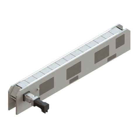
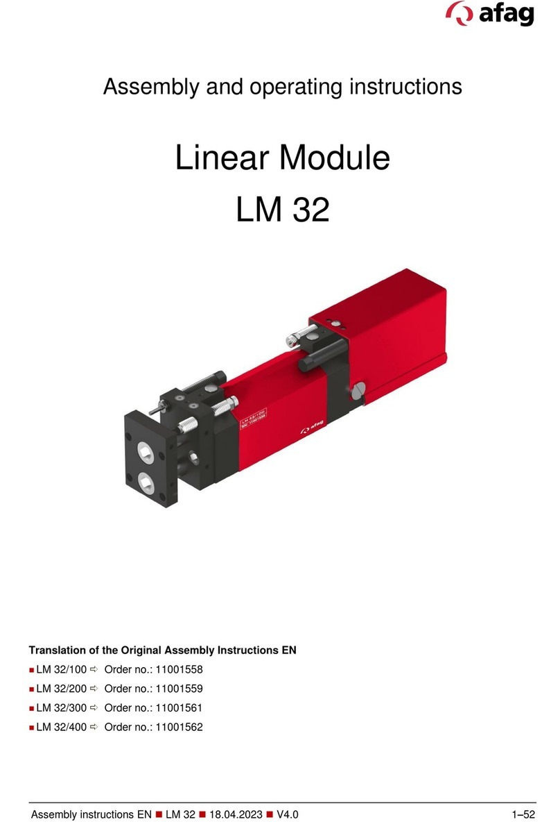
Rotary modules
CR 12 / CR 16 / CR 20
- Declaration of Incorporation
- Module Information
- Montage Instructions
- Maintenance Instructions
„Translation“ of the Original Montage Instructions
© Copyright by Afag Automation AG

2 CR 12 - CR 16 - CR 20 - BA-vers.3.2 gb.21.07.14.docx
These Montage instructions apply to:
Type
Order No.
Type
Order No.
CR 12
50112939
CR 16 / ZA
50112942
CR 12 / ZA
50112940
CR 20
50112943
CR 16
50112941
CR 16 7 ZA
50112945
Version of this documentation: CR12-CR16-CR20-BA-vers.3.2 gb.21.07.14
Symbols:
Assembly and initial start-up must be
carried out by qualified Personnel only and
according to these Montage instructions.
DANGER
Indicates an immediate threatening danger.
Non-compliance with this information can result in death or
serious personal injuries (invalidity).
WARNING
Indicates a possible dangerous situation.
Non-compliance with this information can result in death or
serious personal injuries (invalidity).
CAUTION
Indicates a possibly dangerous situation.
Non-compliance with this information can result in damage to
property or light to medium personal injuries.
NOTE
Indicates general notes, useful operator tips and operating
recommendations which don't affect safety and health of the
personnel.

3CR 12 - CR 16 - CR 20 - BA-vers.3.2 gb.21.07.14.docx
Table of contents
1.0.0 Declaration of Incorporation Page 5
1.1.0 Declaration of Incorporation according to the Machinery Directive
2006/42/EG Page 5
1.1.1 Intended use Page 6
2.0.0 Module Information Page 7
2.1.0 Transport and storage (packing and unpacking) Page 7
2.1.1 Installation and fastening possibilities Page 8
2.1.2 Hole matrix and centering bushings Page 9
2.1.3 Tightening torques for bolts Page 10
2.1.4 Module load factors CR 12 Page 11
2.1.5 Preferred combinations CR 12 Page 12
2.1.6 Module load factors CR 16 Page 13
2.1.7 Preferred combinations CR 16 Page 14
2.1.8 Module load factors CR 20 Page 15
2.1.9 Preferred combinations CR 20 Page 16
3.0.0 Montage Instructions Page 17
3.1.0 Manufacturer address Page 17
3.1.1 Symbols Page 18
3.1.2 General description Page 18
3.1.3 Description of the module Page 19
3.1.4 Includes in the delivery Page 20
3.1.5 Intended use Page 20
3.1.6 Warranty Page 21
3.1.7 Areas of application Page 21
3.1.8 Dimensions drawing for CR 12 Page 23
3.1.9 Technical data of the CR 12 Page 24
3.2.0 Dimensions drawing for CR 16 Page 25
3.2.1 Technical data of the CR 16 Page 26
3.2.2 Dimensions drawing for CR 20 Page 27
3.2.3 Technical data of the CR 20 Page 28
3.2.4 Pneumatic schematically of CR-Module Page 29

4 CR 12 - CR 16 - CR 20 - BA-vers.3.2 gb.21.07.14.docx
3.2.5 Pneumatic connection for CR-Module Page 30
3.2.6 Preparation for start-up Page 32
3.2.7 Adjustment of the angle rotation Page 33
3.2.8 Rotation angle adjust Page 34
3.2.9 Shock absorber adjust Page 35
3.3.0 Adjust the intermediate position for 90° Page 36
3.3.1 As two intermediate position can be approached Page 37
3.3.2 Query sensorik Page 38
3.3.3 Mounting the sensor Page 39
3.3.4 Exchange of the sensors Page 40
3.3.5 Mounting the sensor Page 38
3.3.6 Exchange of the sensors Page 39
4.0.0 Maintenance Instructions Page 41
4.1.0 Maintenance and servicing of the CR-Rotations module Page 41
4.1.1 Servicing Page 42
4.1.2 Accessories for the CR-Module Page 43
4.1.3 Trouble –shooting Page 45
4.1.4 Disassembly and repair Page 46
5.0.0 Disposal Page 47

5CR 12 - CR 16 - CR 20 - BA-vers.3.2 gb.21.07.14.docx
1.0.0 EC Declaration for Incorporation
1.1.0 According to 2006/42/EC dated 09. June 2006, Appendix II B VI for
Incorporation of partly completed machinery.
The manufacturer: Afag Automation AG, Fiechtenstrasse 32, CH-4950 Huttwil
Tel. +41 62 959 87 02, www.afag.com
As manufacturer of the partly completed machine we declare that:
-The specified machine corresponds to the listed essential requirements of the
directive 2006/42/EG, where applicable the other directives and standards
listed below.
Designation: Rotary module compact (pneumatic)
Type: CR 12 / CR 16 / CR 20
Consecutive serial: Nr.50xxxxxx
Machinery Directive 2006/42/EG
-The relevant technical documentation is compiled in accordance with part B of
Annex VI
-The relevant technical documentation in accordance with part B of Annex VI
will be transmitted in response to a reasonable request by the national
authorities in printed from or in electronic from (pdf).
Applied and fulfilled essential requirements:
-1.1; 1.1.1; 1.1.2; 1.2.3; 1.3.3; 1.3.5; 1.3.6; 1.3.7.1.4.1; 1.5; 1.6; 1.6.1;
1.6.3; 1.6.4; 1.7; 1.7.4; 1.7.4.1; 1.7.4.2
-Increase of the harmonized standards applied:
-EN 349; EN ISO 12100-1; EN 12100-2 partly fulfilled
This partly completed machinery must not be put into service until the final machinery
into which it ist o be incorporated has been declared in conformity with the provisions
of this Directive 2006/42/EC, where appropriate.
Name and address of the person authorised to compile the relevant technical
documentation: Lanz Beat, PM & Marketing-Services, Afag Automation AG
Place, date: Huttwil, 21. Juli 2014
Siegfried Egli Markus Werro
Head of HT Managing Director
Afag Automation AG Afag Automation AG
6 CR 12 - CR 16 - CR 20 - BA-vers.3.2 gb.21.07.14.docx
1.1.1 Intended use
The rotary module series CR 12 / CR 16 / CR 20 is used for the rotary movement of
rigidly mounted loads in non-explosion hazardous ambient and deployment
conditions that are suitable for this module according to these Installation
Instructions.
The CR-module has been built according to the present state-of-the-art and the
recognized rules of technical safety. In spite of that its operation may lead to dangers
to life and limb of the user, damage to property or impair the function of the rotary
module.
NOTE
The CR-modules are exclusively designed for rotary movements in
any position with a torque of 0.45 Nm for the CR 12, 1.25 Nm for the
CR 16 and 2.2 Nm for the CR 20, which may represent a danger to
property and the environment if they are operated by unqualified
personnel.
Any other use is regarded as inadequate.
The manufacturer does not accept any liability for damage
resulting from such use. The risk is that of the user alone.
Intended use also includes paying attention to the Installation Instructions and
observing the maintenance and repair instructions specified by the manufacturer.
CAUTION
The CR-module may only be operated and serviced by
correspondingly trained personnel who have also profound
knowledge of the dangers.
The applicable regulations for prevention of accidents and the
other generally accepted safety-relevant and occupational
safety and health regulations are to be followed.

7CR 12 - CR 16 - CR 20 - BA-vers.3.2 gb.21.07.14.docx
2.0.0 Module information
2.1.0 Transport and storage (packing and unpacking)
CAUTION
The CR module is packed in the original cardboard box; if the
module is not handled properly it may fall out of the box when
unpacking and cause injuries to limbs or squeeze your fingers.
NOTE
Consider please! This leaflet should be read by every person who
comes into contact with the module.

8 CR 12 - CR 16 - CR 20 - BA-vers.3.2 gb.21.07.14.docx
2.1.1 Installation and fastening possibilities CR 12 / CR 16 / CR 20
Installation from below
Installation from the sides
Installation from above, screwed
Special screw CR 12 : M4x30, 50001374
Special screw CR16 / CR 20 : M6x36, 11005014
NOTE
Use the centering bushings included in the scope of supply for
positioning and insert these bushings in the borings of the mounting
grid.

9CR 12 - CR 16 - CR 20 - BA-vers.3.2 gb.21.07.14.docx
2.1.2 Centering bushings and hole matrix
Hole matrix at the CR 12 / CR 16 / CR 20 Rotary module
CR 12
CR 16/CR 20
Hole matrix
30mm
Hole matrix
48mm, (30)
Thread / bore hole
2xM4
Thread/bore
hole
2xM6
Centering
bushings (H7)
Ø 7x3mm
Centering
bushings
Ø 9x3mm
Use the centering bushings included in the scope of supply for positioning and insert
these sleeves in the diagonally opposite bore holes of the mounting grid.

10 CR 12 - CR 16 - CR 20 - BA-vers.3.2 gb.21.07.14.docx
2.1.3 Tightening torques for bolts
The screws to be used for assembly must at least satisfy the following conditions:
Standard: VDI 2230
Strength: class 8.8
Surface: galvanized blue, oiled or greased
Thread
Tightening moments
M3
1,1 … 1,4 Nm
M4
2,6 … 3,3 Nm
M5
5,2 … 6,5 Nm
M6
9,0 ... 11,3 Nm
M8
21,6 … 27,3 Nm
This is an incomplete machine
Assembly of the CR Rotary module in a system
The series of the CR Rotary module is used for the linear, smooth movement of
rigidly mounted loads under the ambient and Installation conditions defined for this
module see Technical data. The CR Rotary module can be installed in the horizontal
or vertical position.
NOTE
These Montage Instructions should be read carefully before carrying
out any activity on or with the CR module. The CR module may only
be deployed in accordance with the intended use.
NOTE
Safety instructions
Modifications on the CR Rotary module that are not described in
these Montage Instructions or have not been approved in writing by
Afag Automation AG are not permitted. In case of improper changes
or assembly, installation, operation and maintenance or repairs Afag
rejects all liability.

11 CR 12 - CR 16 - CR 20 - BA-vers.3.2 gb.21.07.14.docx
2.1.4 Module load factors CR 12

12 CR 12 - CR 16 - CR 20 - BA-vers.3.2 gb.21.07.14.docx
2.1.5 Preferred combinations CR 12

13 CR 12 - CR 16 - CR 20 - BA-vers.3.2 gb.21.07.14.docx
2.1.6 Module load factors CR 16

14 CR 12 - CR 16 - CR 20 - BA-vers.3.2 gb.21.07.14.docx
2.1.7 Preferred combinations CR 16

15 CR 12 - CR 16 - CR 20 - BA-vers.3.2 gb.21.07.14.docx
2.1.8 Module load factors CR 20

16 CR 12 - CR 16 - CR 20 - BA-vers.3.2 gb.21.07.14.docx
2.1.9 Preferred combinations CR 20

17 CR 12 - CR 16 - CR 20 - BA-vers.3.2 gb.21.07.14.docx
3.0.0 Montage Instructions
3.1.0 These Montage Instructions are valid for:
Product name: Rotary module compact (pneumatic)
Types: CR 12; CR 12-ZA;
CR 16; CR 16-ZA
CR 20; CR 20-ZA
Fortlaufende Serie: Nr. 50xxxxxx
This is an incomplete machine
This partly completed machinery must not be put into service until the final machinery
into which it is to be incorporated has been declared in conformity with the provisions
of this Directive 206/42/EG, where appropriate.
Name and address of the person authorised to compile the relevant technical
documentation: Lanz Beat, PM & Marketing-Services, Afag Automation AG
18 CR 12 - CR 16 - CR 20 - BA-vers.3.2 gb.21.07.14.docx
3.1.1 Symbols
Assembly and initial start-up must be carried out by qualified personnel only and
according to these instructions.
CAUTION
Indicates a possibly dangerous situation.
Non-compliance with this information can result in damage to
property or light to medium personal injuries.
NOTE
Indicates general notes, useful operator tips and operating
recommendations which don't affect safety and health of the
personnel.
3.1.2 General description
This is an incomplete machine
The series of the CR 12 / CR 16 / CR 20 Rotary module is used for the linear, smooth
movement of rigidly mounted loads under the ambient and Installation conditions
defined, see Technical data.
The CR 12 / CR 16 / CR 20 Rotary module can be installed in the horizontal or
vertical position.
Modifications on the CR 12 / CR 16 / CR 20 Rotary module that are not described in
these Montage Instructions or have not been approved in writing by Afag Automation
AG are not permitted. In case of improper changes or assembly, installation,
operation, maintenance or repairs, Afag Automation AG rejects all liability.

19 CR 12 - CR 16 - CR 20 - BA-vers.3.2 gb.21.07.14.docx
3.1.3 Description of the module
Description CR-ZA
1
2
3
4
5
Flanged shaft
Drive position
Stop screw AS
Shock absorber SD
Lock-nut the shock
absorber
6
7
8
9
10
11
Clamping screw
Clamping plate
Positions picof intermediate stop
Lock-nuts for positioning pin
Housing ZA
Seal for shock absorber
NOTE
The CR is manufactured in accordance with state-of the-art
technology
And the acknowledged safety regulations. However, during use,
danger to life and limb of the operator or damage to the rotary
module and other tangible material could arise.
CAUTION
The CR is designed exclusively for the rotational movement in any
required position with a torque of 0.45 Nm for CR 12 and 1.25 Nm for
CR 16 and 2.2 Nm for CR 20 which, when handled, do not react in a
way which could endanger persons, objects or the environment.
Any application beyond this is not appropriate.
The manufacturer accepts no liability for damage resulting from
improper use. The risk is borne solely by the user.
1
2
3
5
4
6
7
8
10
9
11

20 CR 12 - CR 16 - CR 20 - BA-vers.3.2 gb.21.07.14.docx
3.1.4 Includes in the delivery
Pos.
Quant.
Description
1
2
Module
Shock absorber with lock nut and seal
2
3
2
2
Centering bushings7x3, (9x4 mm)
Special screw
3.1.5 Intended use
The series of the CR rotary module is used for the rotary movement of rigidly
mounted loads under the ambient and Installation conditions defined for this module;
see Technical catalogue.
NOTE
These Montage Instructions should be read carefully before carrying
out any activity on or with the module.
The module may only be deployed in accordance with the intended
use.
Modifications on the module that are not described in these Montage
Instructions or have not been approved in writing by Afag are not
permitted. In case of improper changes or assembly, installation,
operation, maintenance or repairs, Afag rejects all liability.
CAUTION
Connection of compressed air and operation of pneumatic
systems may cause unpredictable movements which may result
in personal injury or damage to property.
When connecting compressed air for the first time make sure that all air throttles are
closed. Aerate the system slowly.
Other manuals for CR 12
1
This manual suits for next models
4
Table of contents
Other Afag Control Unit manuals

Afag
Afag RE-50 User manual

Afag
Afag LTM-V-100 Quick reference guide

Afag
Afag PG 12 User manual

Afag
Afag GMQ 32/RM 16 User manual

Afag
Afag Compact Slide CS 8 User manual

Afag
Afag RM 63 User manual

Afag
Afag PG 12 Technical specifications

Afag
Afag LM 32/200 User manual

Afag
Afag CS 25 User manual

Afag
Afag CR 25 Quick reference guide
Popular Control Unit manuals by other brands

Whelen Engineering Company
Whelen Engineering Company WeCan Series installation guide

Quectel
Quectel LTE-A Series Hardware design

Hach
Hach sc200 user manual

Anderson
Anderson Greenwood Series Installation and maintenance instructions

Beckhoff
Beckhoff KM2002 Documentation

EisSound
EisSound 400 Series User and installation manual