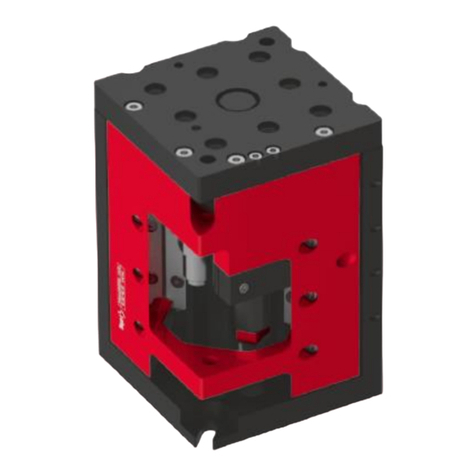
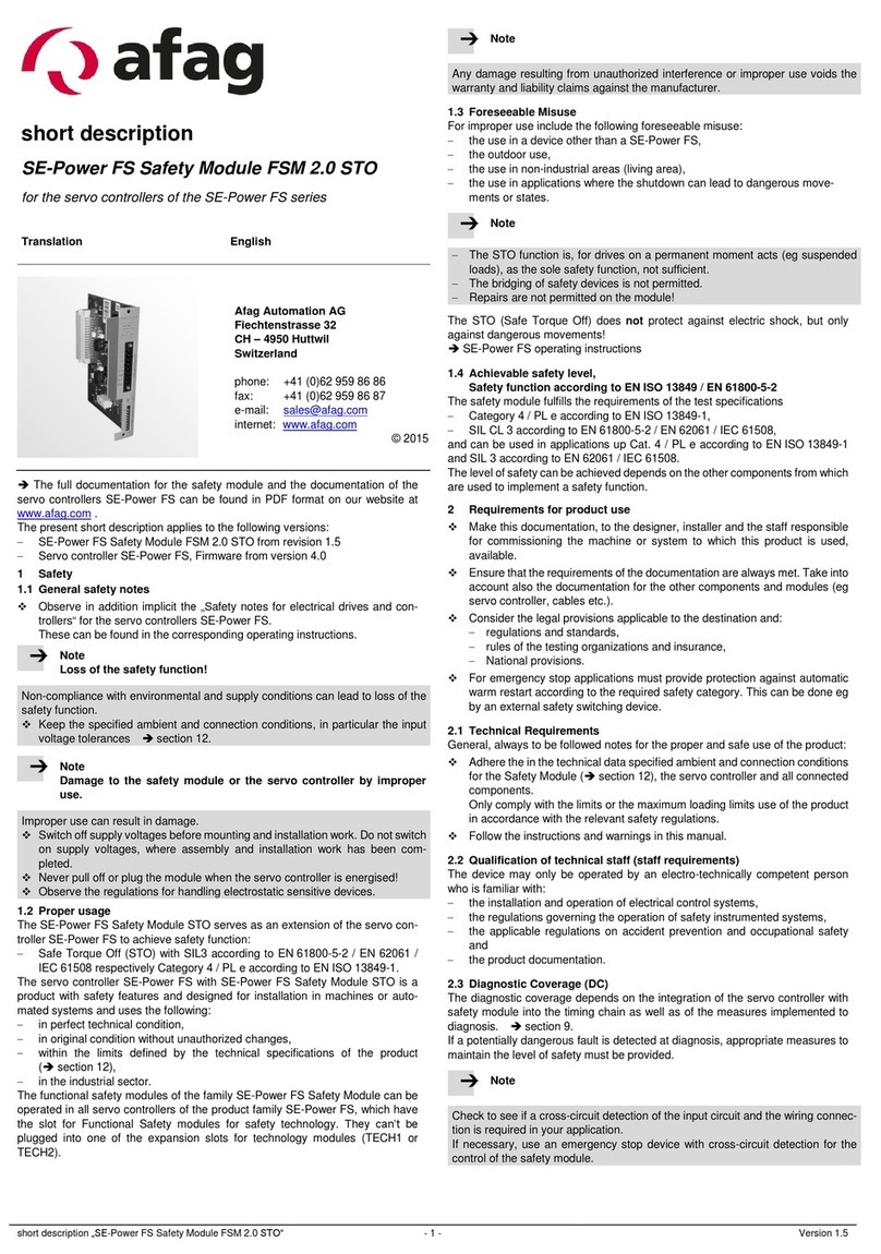
Afag PG 12 Technical specifications

Precision gripper modules
PG 12 I PG 16 I PG 20
Declaration of Incorporation
Module Information
Montage Instructions
Maintenance Instructions
„Translation“ of the Original Montage Instructions
© Copyright by Afag Automation AG

2PG 12-PG 16-PG 20-OI-v.1.2 gb.13.12.12
These Montage Instructions apply to: Precision gripper modules PG
Type
Order No.
PG 12
50332223
PG 16
PG 20
50332224
50332225
Version of this documentation: PG 12-PG 16-PG 20-OI-v.1.2 gb.13.12.12
Symbols:
Assembly and initial start-up must be car-
ried out by qualified Personnel only and
according to these Montage Instructions.
DANGER
Indicates an immediately threatening danger.
Non-compliance with this information can result in death or se-
rious personal injuries (invalidity).
WARNING
Indicates a possibly dangerous situation.
Non-compliance with this information can result in death or se-
rious personal injuries (invalidity).
CAUTION
Indicates a possibly dangerous situation.
Non-compliance with this information can result in damage to
property or light to medium personal injuries.
NOTE
Indicates general notes, useful operator tips and operating recom-
mendations which don't affect safety and health of the personnel.

PG 12-PG 16-PG 20-OI-v.1.2 gb.13.12.12 3
Table of Contents
1.0 Déclaration of incorporation..........................................................................5
2.0 Module Information.........................................................................................6
2.1 Safety instructions.............................................................................................6
2.2 Transport, handling, storage.............................................................................6
2.3 Description of the module parts........................................................................7
2.4 Parts designation..............................................................................................8
2.5 Mounting, connection........................................................................................8
2.6 Installation and fastening possibilities.............................................................. 9
2.7 Dimensional drawing PG 12 ...........................................................................10
2.8 Technical data PG 12 .....................................................................................11
2.9 Dimensional drawing PG 16 ...........................................................................12
2.10 Technical data PG 16 .....................................................................................13
2.11 Dimensional drawing PG 20 ...........................................................................14
2.12 Technical data PG 20 .....................................................................................15
2.16 Tightening moments for bolts..........................................................................19
2.17 Assembly of the gripper fingers.......................................................................19
2.18 Pneumatic connection.....................................................................................20
3.0 Montage InstructionsFehler! Textmarke nicht definiert. ...............................21
3.2 Intended use...................................................................................................22
3.2 Warranty.........................................................................................................23
3.3 Safety instructions...........................................................................................23
3.6 Start-up...........................................................................................................25
3.7 Adjustment, retrofitting....................................................................................25
3.8 Standard operation .........................................................................................26
4.0 Maintenance Instructions.............................................................................27
4.1 Maintenance and servicing.............................................................................27
Regular maintenance..................................................................................... 27
Further maintenance...................................................................................... 27
4.2 Maintenance...................................................................................................28
4.3 Troubleshooting..............................................................................................29
4.4 Spare parts.....................................................................................................30
4PG 12-PG 16-PG 20-OI-v.1.2 gb.13.12.12
4.5 Delivery...........................................................................................................30
4.6 Disassembly and repair ..................................................................................30
4.7 Disposal..........................................................................................................31
5.0 Appendix .......................................................................................................31
5.1 List of figures ..................................................................................................31
5.2 List of tables....................................................................................................31

PG 12-PG 16-PG 20-OI-v.1.2 gb.13.12.12 5
1.0.0 Déclaration for Incorporation
1.1.0 According to 2006/42/EC dated 09. June 2006, Appendix II B VI for
Incorporation of partly completed machinery.
The manufacturer: Afag Automation AG, Fiechtenstrasse 32, CH-4950 Huttwil
Tel. 0041 (0)62 959 87 02, www.afag.com
As manufacturer of the partly completed machine we declare that:
-The specified machine corresponds to the listed essential requirements of the
directive 2006/42/EG, wehere applicable the other directives and standards
listed below.
Producte name:
Precision Gripper Modules PG
Types:
Consequtive serial:
PG 12 - PG 16 - PG 20
No. 50xxxxxx
Machinery Directive 2006/42/EG
-The relevant technical documentation is compiled in accordance with part B of
Annex VI
-The relevant technical documentation in accordance with part B of Annex VI
will be transmitted in response to a reasonable request by the national authori-
ties in printed from or in electronic from (pdf).
Note to the Declaration of Incorporation according to the Machinery Directive
2006/42 /EC, Annex IIB, section 4. ( Checklist on accurate and basic health and safety
requirements).
-1.1; 1.1.1; 1.1.2; 1.2.3; 1.2.4.4; 1.3; 1.3.5; 1.3.6; 1.3.7; 1.3.9; 1.4.1; 1.5; 1.5.3;
1.6; 1.6.1; 1.6.3; 1.6.4; 1.7; 1.7.4; 1.7.4.1; 1.7.4.2
-Increase of the harmonized standards applied:
-EN ISO 12100-1; EN 12100-2 partly fulfilled
This partly completed machinery must not be put into service until the final machinery
into which it is to be incorporated has been declared in conformity with the provisions
of this Directive 2006/42/EC, where appropriate.
Name and address of the person authorised to compile the relevant technical documentation:
Lanz Beat, PM & Marketing-Services, Afag Automation AG
Place/Date: Huttwil, 13. Dez. 2012
Afag Automation AG
Marc Zingg
Managing Director
Mathias Schütz
Product Manager

6PG 12-PG 16-PG 20-OI-v.1.2 gb.13.12.12
2.0 Module Information
2.1 Safety instructions
Modifications to the PG precision gripper that are not described in this Montage In-
structions or have not been approved in writing by the company Afag Automation AG
are not permitted. In case of improper changes or assembly, installation, operation,
maintenance or repairs, Afag Automation AG rejects all liability.
2.2 Transport, handling, storage
The following conditions must be met for transport and storage:
Storage temperature: 0 - 50 ℃
Humidity: <90%, non condensing
CAUTION
The PG precision grippers are packed in the original box. In the
case of improper handling the module may drop out of the box
when it is unpacked and cause injuries to limbs.
NOTE
A package slip is supplied with every module from Afag Automation
AG. Please follow the instructions before installing the module into a
station or a system.

PG 12-PG 16-PG 20-OI-v.1.2 gb.13.12.12 7
2.3 Description of the module parts
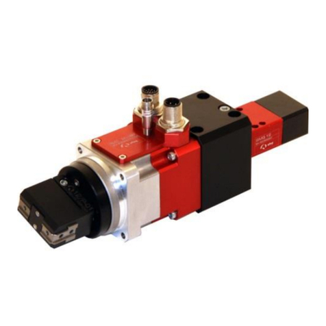
The Afag PG precision gripper is the right solution when it comes to gripping and
precise insertion of parts.
The PG precision grippers are precise and compact gripping modules designed for
gripping oriented serial parts. They can be combined with other modules from the
Afag modular kit. The positions “open” and “close” can be queried by initiators (not
included in the scope of delivery, must be ordered separately). The grippers have a
repeatability of +/- 0.01 mm, the turning precision of the grippers is +/- 0.05 mm.
The gripping forces are indicated in the corresponding table of the gripper type in
these instructions.
NOTE
Please note:
Modifications to the PG precision gripper that are not described in
this Montage Instructions or have not been approved in writing by the
company Afag Automation AG are not permitted. In case of improper
changes or assembly, installation, operation, maintenance or repairs,
Afag Automation AG rejects all liability.

8PG 12-PG 16-PG 20-OI-v.1.2 gb.13.12.12
2.4 Parts designation
1 Gripper housing
2 Gripping head
3 Gripper jaws
4 Mounting grid at the rear and at the sides
5 Air connections at the rear and at the sides
6 Holders for sensors
7 Mounting holes for options such as holding-down appliances
Figure 1: Module description
2.5 Mounting, connection
WARNING
The gripper fingers are moved by the pneumatic control. If the
gripper fingers cannot move freely there is danger of injuries
and bruises near the add-ons.
If add-ons at the PG grippers could cause danger in connection
with the gripper fingers a safe operation must be ensured.
2
3
1
7
4
6
4
5
5

PG 12-PG 16-PG 20-OI-v.1.2 gb.13.12.12 9
WARNING
Due to the decentral controller the operator of the PG needs not
to be near the product so that third persons might be endan-
gered by the gripper operation.
Always switch off the controller and disconnect the module
from the compressed air supply and secure against being
switched on again unintentionally when you work on the PG
precision gripper. The signals of the control system may cause
unintentional movements of the module which may lead to per-
sonal injuries.
2.6 Installation and fastening possibilities
The PG precision grippers can be installed in a vertical and horizontal position.
The Afag module components are provided with a precise module centring which
guarantees a high and repetitive accuracy of fit during installation, operation and ex-
change of a module.
Installation of the precision grippers
Use the centring bushings included in the scope of delivery for positioning.
Attachment at the sides
The precision grippers can be mounted at the and at the sides.

10 PG 12-PG 16-PG 20-OI-v.1.2 gb.13.12.12
2.7 Dimensional drawing PG 12
Figure 2: Installation and fastening possibilities

PG 12-PG 16-PG 20-OI-v.1.2 gb.13.12.12 11
2.8 Technical data PG 12

12 PG 12-PG 16-PG 20-OI-v.1.2 gb.13.12.12
2.9 Dimensional drawing PG 16

PG 12-PG 16-PG 20-OI-v.1.2 gb.13.12.12 13
2.10 Technical data PG 16

14 PG 12-PG 16-PG 20-OI-v.1.2 gb.13.12.12
2.11 Dimensional drawing PG 20

PG 12-PG 16-PG 20-OI-v.1.2 gb.13.12.12 15
2.12 Technical data PG 20

16 PG 12-PG 16-PG 20-OI-v.1.2 gb.13.12.12
2.13 Preferred combinations to PG 12

PG 12-PG 16-PG 20-OI-v.1.2 gb.13.12.12 17
2.14 Preferred combinations to PG 16

18 PG 12-PG 16-PG 20-OI-v.1.2 gb.13.12.12
2.15 Preferred combinations to PG 20

PG 12-PG 16-PG 20-OI-v.1.2 gb.13.12.12 19
2.16 Tightening moments for bolts
The screws to be used for assembly must at least satisfy the following conditions:
Standard: VDI 2230
Strength: class 8.8
Surface: galvanized blue, oiled or greased
Thread
Tightening moments
M2
M2,5
M3
0,3 … 0,35 Nm
0,5 … 0,73 Nm
1,1 … 1,4 Nm
M4
2,6 … 3,3 Nm
M5
5,2 … 6,5 Nm
M6
9,0 ... 11,3 Nm
M8
21,6 … 27,3 Nm
Table 1: Tightening moments for bolts
2.17 Assembly of the gripper fingers
NOTE
The gripper fingers are positioned by means of centring bushings; in
addition we recommend to provide a recess or a groove on the grip-
per fingers to secure them against twisting
(see drawing below).
Example: connecting geometry gripper fingers

20 PG 12-PG 16-PG 20-OI-v.1.2 gb.13.12.12
2.18 Pneumatic connection
Pneumatic diagram of the PG modules. Two pneumatic connections each are at the
rear and at the sides of the base body of the PG pneumatic gripper. Please see the
Technical dimensional drawings in this manual.
Operating pressure: 6 bar +/-2
NOTE
Please note:
Close air connections which are not used air-tight before installing
the module in a system.
Carry out a leakage test.
(P1)
(P2)
P1 = open
P2 = close
1 Compressed air connection 4 One-way restrictor
2 Maintenance unit 5 Gripper (PG)
3 5/2 port directional control valve P1/P2 Air connection
Other manuals for PG 12
2
This manual suits for next models
2
Table of contents
Other Afag Control Unit manuals

Afag
Afag CR 12 User manual

Afag
Afag RM 63 User manual

Afag
Afag LTM-V-100 Quick reference guide

Afag
Afag RM12 RMZ 16 User manual

Afag
Afag LM 32/200 User manual

Afag
Afag CR 25 Quick reference guide

Afag
Afag CS 25 User manual

Afag
Afag LM 12 User manual

Afag
Afag SE-Power FSM 2.0 MOV User manual

Afag
Afag LM 12/30 User manual
Popular Control Unit manuals by other brands

Sun Oracle
Sun Oracle Sun Blade X6275 M2 installation guide

Danfoss
Danfoss 088U0200 instructions

Pentair
Pentair Autotrol 255 Series Service manual

Pickering
Pickering 40-292 user manual

Motorline professional
Motorline professional MC15BA User& installer's manual

ZIEHL-ABEGG
ZIEHL-ABEGG CBG-30AV operating instructions