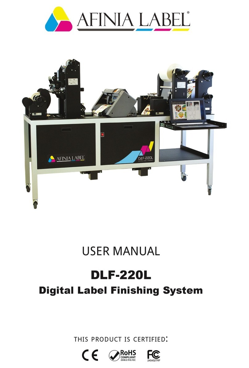
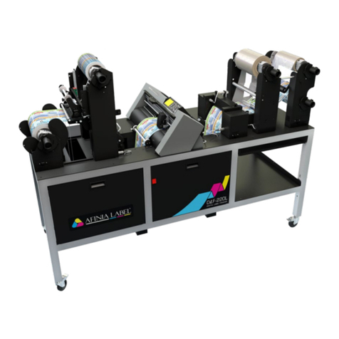
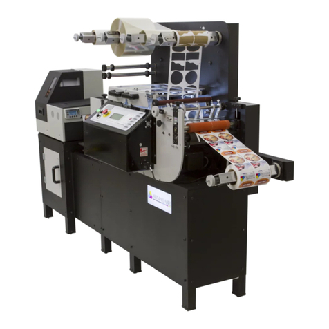
AFINIA LABEL Mini DLF Series User manual

REV. 3.0
Mini DLF Series
USER MANUAL
DLF-140S / DLF-220S
Tabletop Label Finishing Systems
v 3.0


IMPORTANT: Please keep the original packaging in
case you need to return the material. If we receive the
system in non-original packaging, the warranty will be
void.
IMPORTANT: The latest version of the DLF Series
software is available on our websites, afinialabel.com
or afinialabel.co.uk

SAFETY
The machine has to be installed in the specif place where only the autorised and trained
technician can have the access.
ATTENTION! Sharp cutter.
Install the machine on a stable and robust table.
Ground connection mandatory, so please connect the machine to a power outlet with
ground connection.
Only the plotter Graphtec CE7000-40 can be used on this machine.
ELECTRONIC AND TECHNICAL DETAILS:
Input: 100-240V~ 2.0A, 50-60Hz
Power cord: 3 x 0.75 mm2
Fuse: T3.15 A 250 V
Working temperature: -10° / +40°
Working Humidity: 15-80%
In Denmark: “Apparatets stikprop skal tilsluttes en stikkontakt med jord som giver
forbindelse til stikproppens jord.”
In Finland: “Laite on liitettävä suojakoskettimilla varustettuun pistorasiaan”
In Norway: “Apparatet må tilkoples jordet stikkontakt”
In Sweden: “Apparaten skall anslutas till jordat uttag”

I N D E X
.....................................................................page 3
.........................................................................................page 5
.....................................................................................page 5
....................................page 6
...............................................................................page 8
.........................................page 8
.................................................................................page 9
................................................page 10
.................page 11
.............................................................page 12
................................................................................page 13
.....................................page 13
...........................................................................................page 26
...................................................................................page 26
.............................................................................page 26
........................page 27
.................................................................page 28
................................................................................page 28
...............................................................................page 29
....................................................................page 29
....................................page 31
...................................................................................................page 32
................................................................................page 32
...............................................................................page 33
................................................................................page 34
..............................................................................page 36
...................................................................page 36
....................................................................page 37
...........................................................................................page 38
How to install the cutting plotter
Software activation
System requirements
How to load and operate with the lamination module
How to adjust the clutch
How to load the laminated media into the plotter
How to run the cut test
How to load the matrix remover core holder
How to load the rewinder core holder and set the slitter module
How to add or remove blade holder
Metal guides alignment
Remove unwanted waste from the edge of the roll
Error Messages
Black-mark detection
Black-mark position in the media
How to cut blank labels
How to update software
How to restore plotter settings
When and how to reduce the plotter feeding speed
Media path
Tension arm calibration
Modules speed rotation
Graphtech mantenaice
How to replace the knife
How to replace the slitter blade
How to replace the cutting mat
Troubleshooting 2
Afinia Cutting Manager Software .............................................................page 14
HOW TO INSTALL THE CUTTING PLOTTER
1. Click on “Setup DLF-Software...” and
follow the step by step instructions to
complete the installation.
Please DO NOT connect the Afinia USB
to your pc before the installation is
complete
2. Click NEXT
4. Click NEXT 5. Click YES
6. In process
3
7. Click NEXT
3. Click NEXT

4
9. Click OK
10. Click NEXT (Remove the Afinia USB
from your pc, and turn off the Afinia)11. Click NEXT
12. Choose the right model name of your
Graphtec (CE7000-40).
Click NEXT
13. Wait until the sign “Update for
the Graphtec CE7000-40 driver was
completed” shows up. You may need to
restart the computer.
Click OK
The installation is completed. A Afinia CM shortcut is displayed on your desktop
8. Click FINISH

5
Plug in the USB camera and the USB dongle, they will auto-install.
If your computer already has a camera installed, we recommend disabling it. If you
do not, your pc will ignore the camera on the plotter.
CM Software will generate a folder in the Windows start menu.
The Cutting Manager software works on Windows
OS from Windows 8.1. We do not guarantee its
functionality on previous versions. Not compatible
with macOS systems.
SYSTEM REQUIREMENTS
To activate the software you must have these things:
- The unit’s key, which can be found attached to the plotter and the software manual.
WHEN YOU ACTIVATE THE LICENSE YOU MUST BE CONNECTED TO INTERNET
If upgrading the software on an older DLF finisher, select the 1st option, search
for the dongle.
SOFTWARE ACTIVATION

Load the printed roll against the disk.
Tighten the core holder.
Load the lamination roll, move it along
the supply shaft and make it match with
the web, tighten the core holder.
IMPORTANT: the lamination roll always
needs to be narrower than the web width.
6
HOW TO LOAD AND OPERATE THE LAMINATION MODULE
MEDIA TENSION CONTROL
Load the media into the nip roller.
A) Display
B) ON/OFF : activate/deactivate the tension control
+: increase the media tension
-: decrease the media tension
C) Ultrasonic sensor
Display conditions:
the tension level set
Keeping “run” pressed; the core will spin
A
C
B
Each core holder (ON THE LAMINATING & UNWINDING MODULE) is managed by its own
controller designed to set the required media tension, keeping that tension
automatically constant even the roll diameter variation during the job.

FORWARD
MEDIA
ON-OFF
pull it underneath the guide roller, center it
Push “On-O” button to active the automatic media feeding mood. The green led will be
on.
The error occurs when the media roll, lamination roll or both are not loaded, broken or
simply they are run out.
To clear the error it is just necessary to restart the module pushing “On-O” Button.
7
media feeding is active. It operates
keeping pushed “Forward Media”
button.
Close the nip roller once the media has
been loaded.

adjustments. If the tension is too tight, the roller system may be damaged; if the tension
is too loose, the media will not be laminated properly.
Pull the laminated media under the tension arm, then pass it between the aluminium
rollers. The guide can be adjusted to prevent the media from shifting.
Put the lever, located in the rear of the plotter, in the down position.
Pull the media through the plotter, keeping the media edge in contact with the alignment
points.
Set both pinch rollers at the media edge.
8
WHEN TO ADJUST THE CLUTCH
HOW TO LOAD THE LAMINATED MEDIA INTO THE PLOTTER
While holding the media in the aligned position with one hand, lift the handle on the rear
of the plotter with the other to secure the media.
Press button 2 as requested on plotter’s display.

9
>> How to run the black-mark mode
User Interface at page 14 might be helpful.
1. Open Afinia Cutting Manager.
2. Press “OPEN PDF” or “OPEN LAST JOB” to load the Cut File.
3. Look at the camera preview, hold down “BACKWARD MEDIA” or “FORWARD MEDIA”
arrows to move the web until the black-mark goes in the center position of the blue
rectangle area.
4. Measure the distance in (MM) between the top of one black-mark to top of the next
black-mark, key in this value in the “DISTANCE BETWEEN BLACKMARKS” box section.
6. Press “CUT TEST” to check for cut depth. If the liner has been cut, decrease the cutter
pressure value in the cut force box. If label doesn’t detach, increase the cutter pressure
value in the cut force box.
7. Make sure label is aligned with the cut. Through X and Y values in the software,
HOW TO RUN THE CUT TEST AND START A JOB
++
8. Once the cut settings are properly set, select “COPY MODE” ON if you desire a preset
quantity of copies or OFF if to cut until the media roll is empty.
9. Set the black-mark size” in “BLACK-MARK MODE” area.
10. Press “START”.
IMPORTANT:
Whenever you lower and rise the lever while you are in black-mark
mode, hold down the forward media arrow button to move again the
plotter’s head down

>> How to run the blank mode
2. Set the copy mode ON, and set 2 as number of copies.
3. Click “START”.
4. Check the horizontal position and the gap between the cuts.
6. Once the cut is set properly, select copy mode: ON if you desire a preset quantity of
copies, or OFF to cut until the media roll is empty.
7. Click “START”.
10
WARNING: Before starting a job, always remove the waste
media from the matrix remover core.
Tape the matrix securely onto the cardboard core.
System operating issues may occur if the above
suggestions are not followed.
HOW TO LOAD THE MATRIX REMOVER CORE HOLDER
1. Load empty cardboard core(s) and tighten the core holder, then place the motorized
core holder in position.
2. Peel back the matrix.
3. Pull the matrix and attach it to the matrix remover core holder.
4. Pull down the waste press and relocate the o-rings to be over the waste matrix.
5. Close the sponge roller (not strong).
WASTE

1. Load empty cardboard core(s) and tighten the core holder, then place the motorized
core holder in position. Tighten the core holder.
2. Pull the media through the aluminium rollers and attach the labels to the core using a
waste label.
HOW TO LOAD THE REWINDER CORE HOLDER AND SET THE
SLITTER MODULE
11
OPEN CLOSE
B
C
A
A
BC
Slitter module has 3 positions:
- Upper position (A), the blades are lifted to allow the media loading;
- Middle position (B), align the blades with the edges and the center of the labels, tighten
the thumb screw once the blade is in position;
- Lower position (C), the blade cut the media.

3. Turn ON the Matrix Remover module to rewind and start to slit the media, then turn OFF
5. Make sure the tension on all rolls is even, and attach each label to the core using a
waste label or tape.
6. Turn the Matrix Remover module ON. Press Resume to continue.
12
Remove the iron bar by unscrewing
the black thumb screw.
1
Replace the slide iron bar and rescrew
the thumb screw.
2
HOW TO ADD OR REMOVE A BLADE HOLDER

Media guides should be adjusted in
order to prevent the web from shifting
position.
METAL GUIDES ALIGNMENT
13
Position the blade holders according
the job requirements.
HOW TO CUT OUT THE EXTERNAL TRIMS
Pull up the trims keeping them behind
the roller with guides.
Attach the trims onto the waste
removal core.
Move the guides to drive the rewinding
trims on the desired position.
It is recommend to keep them inside
the removed label area.
IMPORTANT: the external trims too
thin may break, we recommend at
least 4mm wide.

1
17
16
2
15
6 7
8
14
10
9
12
3
13
4 5
Afinia cutting manager (Afinia CM)
USER INTERFACE
11
20
18 19
2
21 22
23
14

1.
2.
3.
4.
5.
6.
7.
8.
9.
10.
11.
12.
13.
14.
15.
16.
17.
18.
19.
20.
21.
22.
23.
-x +y
+x -y
15

Settings (24)
1
2
3
4
15
6
7
8
9
101112
13
14
ADVANCED OPTIONS
24
26
24.
25.
26.
27.
28.
29.
27
28
29
5
25
1.
2.
3.
16

X axis
CUTTING
DIRECTION
-
-
CUTTING
DIRECTION
+
+
STEP 1
VERIFY THE
CORRESPONDENCE OF
THE CUT WITH THE PRINT
STEP 2
AT THE POINT INDICATED,
ADJUST OFFSET TO ALIGN
THE CUT WITH THE PRINT
STEP 3
INCREASE OR DECREASE
THE “STRETCH”
PARAMETER (X)
-
4.
5.
6.
17
This manual suits for next models
2
Table of contents
Other AFINIA LABEL Label Maker manuals

AFINIA LABEL
AFINIA LABEL LT5C User manual

AFINIA LABEL
AFINIA LABEL L301 Specification sheet

AFINIA LABEL
AFINIA LABEL AP200 User manual

AFINIA LABEL
AFINIA LABEL L901 User manual

AFINIA LABEL
AFINIA LABEL Afinia 502 User manual

AFINIA LABEL
AFINIA LABEL DLF-220L User manual

AFINIA LABEL
AFINIA LABEL Afinia L501 User manual

AFINIA LABEL
AFINIA LABEL Afinia 502 Specification sheet

AFINIA LABEL
AFINIA LABEL DLF L Series User manual

AFINIA LABEL
AFINIA LABEL L801 User manual