manuals.online logo
Brands
  1. Home
  2. •
  3. Brands
  4. •
  5. AFRISO
  6. •
  7. Controllers
  8. •
  9. AFRISO ARM ProClick User manual

AFRISO ARM ProClick User manual

Electric actuators ARM ProClick
Art.-No 14 323 10, 14 343 10, 14 343 11
NOTICE!
This instruction manual is also available on www.afriso.pl.
MOUNTING ON AN ARV ProClick VALVE
The ARM ProClick valve is factory set on 50% (position “5” on the scale). To mount the actuator pro-
perly on the valve, the valve must also be set on 50%.
WARNING!
The product may only be mounted, commissioned and disposed of by quali-
ed, specially trained staff.
Alterations performed by unauthorized staff may cause a threat and are for-
bidden for safety reasons.
The product is powered by 230 V AC voltage. This may cause severe injuries
or death.
Do not let the product go into contact with water.
Before mounting the product please read the manual of the mixing valve.
APPLICATION
SCOPE OF DELIVERY
INSTRUCTION MANUAL
Electric actuators ARM ProClick are designed to operate on 3-/4-way rotary mixing valves, which requ-
ire a maximum turning torque of 6 Nm. They have a turning angle of 90˚. The ARM ProClick actuator
should be connected to a 3-point controller with a 230 V AC supply voltage. One can operate the actu-
ator also manually using the knob. The ARM ProClick actuators are mainly used to mix two streams via
the mixing valve, to obtain a set temperature on the outlet connection of the valve.
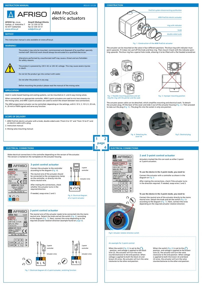
One can mount the actuator in 4 positions on the valve. The blue ring with indicator must point
upwards. If it does not, pull off the knob and blue ring. Then mount it back with the indicator pointing
upwards. The blue ring has a special hole inside to lift it with a at screwdriver.
1. Take off the knob and blue limiting ring from the ARV ProClick valve (Drawing 1). To do this, just
pull the parts along the spindle axis. The knob construction allows to lift it with a at screwdriver.
There are special holes on two sides of the knob.
2. Set the valve on 50%, so that the sleeve inside the 3-way valve will be right in the middle between
the hot and cold inlets (Drawing 2 or Drawing 3, Drawing 5) or just in the middle of the outlet
connections in a 4-way valve (Drawing 4, Drawing 6).
3. Slide the actuator on the mixing valve, so that the 4 pins of the ProClick mechanism nd themselves
in the appropriate holes on the back of the actuator and the mechanism locks on them (Drawing 7).
The ProClick mechanism requires no tools.
4. Insert the double-sided scale in the correct position according to the opening/closing direction
(“from 0 to 10” or “from 10 to 0). Follow the rules below:
- if turning the knob right (clockwise) closes the valve, choose the scale “from 0 to 10”,
- if turning the knob left (counter-clockwise) closes the valve, choose the scale “from 10 to 0”.
The blue indicator should point at “5” on the scale. If not, please return to point 2.
5. Connect the actuator to the controller according to the scheme
(Drawing 10). The electric cable of the actuator can be detached.
This makes mounting and electrical connections easier. To take
out the plug, one must lift the lever of the cover and slide it out
(Draw ing 11). Next detach the plug (Drawing 12). The plug ts
into the socket only in one position.
Drawing 1. View on the ARV ProClick valve with removed knob
Drawing 7. Mounting the ARM ProClick actuator
Drawing 9. View on two sides of the scale
Drawing 10. Electrical scheme
Drawing 11. Detaching the cover Drawing 12. Electrical plug
Drawing 8. Possible mounting positons
ARV ProClick valve
4 pins of the ProClick mechanism
attening on the adapter
pushbutton of the ProClick mechanism
ARM ProClick actuator
ring with indicator
double-sided scale
knob
Drawing 2. 3-way, position 1 Drawing 3. 3-way, positon 2 Drawing 4. 4-way
Drawing 5. 3-way Drawing 6. 4-way
1. Electric actuator ARM ProClick with a knob, double-sided scale (“from 0 to 10” and “from 10 to 0”)
and an electric cable with plug.
2. Mounting set for ARV valves without ProClick system (rst generation) – not included in Art.-No 14 343 11.
3. Instruction manual.
953.001.0061 1
AFRISO Sp. z o.o.
Szałsza ul. Kościelna 7
42-677 Czekanów
Poland
www.afriso.pl
Customer service
Tel. +48 330 33 55
Fax: +48 330 33 51
[email protected]
mixed
stream
mixed
stream
mixed
stream
hot
stream
hot
stream
cold
stream cold
stream
closing
direction
closing
direction
Connect the controller to the power supply according to the producer’s manu-
al or guidelines.
Connect the neutral wire N direct to the mains supply or to the controller,
if it gives such a possibility.
3-point
controller
actuator
wires
1 2
43
Parameter / piece Value / description
Torque 6 Nm
Turning angle 90O
Turning time by 90OARM 323: 60 s
ARM 343: 120 s
Control signal / power supply 3-point / 230 V AC
Working temperature 0-50OC
Power consumption 2,5-4 VA
Safety class II
Protection class IP42
Dimensions (H x W x D) 85,5 x 97 x 99 mm
Housing PC
Cable length 2 m with plug
USING THE ARM ProClick ACTUATOR
MOUNTING ON AN FIRST GENERATION ARV VALVE OR OTHER PRODUCER’S
VALVES
1. Mode pushbutton
One must push the button to change from automatic to manual mode.
The mode pushbutton in the upper positon indicates automatic mode. When it is pushed down, one
can operate the actuator manually via the knob.
2. Signalling LEDs
The LEDs on the left and right inform about the turning direction of the actuator and valve. The left
one indicates turning counter-clockwise and the right clockwise. The shine also when the actuator is in
an end position but the controller still supplies power to the actuator. Observing the LEDs provides fast
diagnosis after nishing the assembly.
3. Position of the knob with scale
After mounting the actuator on the mixing valve and correctly choosing the scale, position “0” should
mean a valve fully closed (hot water closed) and position “10” a fully open valve (hot water open).
Every other position will indicate a percentage of opening, e.g. position “4” means that the valve is
open in 40%.
4. Taking the actuator off the valve
To take off the actuator from the valve, press the pushbutton of the ProClick mechanism (1) and slide
the actuator from the valve (2).
TECHNICAL DATA
MAINTENANCE
DECLARATIONS AND STATEMENTS
DISMOUNTING, DISPOSAL
WARRANTY
CUSTOMER SATISFACTION
The ARM ProClick valve is factory set on 50% (position “5” on the scale). To mount the actuator pro-
perly on the valve, the valve must also be set on 50%.
Full list of mounting sets for rst generation of ARV valves
and other producer’s valves is to be found in the technical
price catalogue on www.afriso.pl.
1. Take off all the plastic parts from the valve, that will not be used.
2. Set the valve on 50%, so that the sleeve inside a 3-way valve will be right in the middle between
the hot and cold inlets (Drawing 5) or just in the middle of the outlet connections in a 4-way valve
(Drawing 6).
3. Place the adapter on the stem of the valve and screw it down. Screw the two counter screws into the
valve (Drawing 13). In rst generation of AFRISO ARV valves (and most of other producer’s valves),
the triangle on the adapter is in the same position as the attening on the stem and indicates the
sleeve position inside the valve. To screw in the counter screws into rst generation of AFRISO ARV
valves, sizes DN40 and DN50, one must unscrew the tightening Allen screws rst (Drawing 14).
4. Slide the actuator on the valve, so that the 2 counter pins t inside the appropriate holes in the back
of the actuator and the mechanism locks itself on them. The construction of the actuator allows
to mount it in different positions (Drawing 8). The blue ring with indicator must point upwards.
If it does not, one should pull off the knob and blue ring. Then mount it back with the indicator
pointing upwards.
5. Insert the double-sided scale in the correct position according to the opening/closing direction
(“from 0 to 10” or “from 10 to 0) (Drawing 9). The blue indicator should point at “5” on the scale.
If not, please return to point 2.
6. Connect the actuator to the controller according to the scheme (Drawing 10). The electric cable
of the actuator can be detached. This makes mounting and electrical connections easier. To take
out the plug, one must lift the lever of the cover and slide it out (D rawing 11). Next detach the plug
(Drawing 12). The plug ts into the socket only in one position.
3-way
4-way
Drawing 13. Mounting the ARM ProClick actuator on an ARV valve
Drawing 17. Dismounting the ARM ProClick actuator
Drawing 15. Mode pushbutton
Drawing 16. LEDs
Drawing 14. ARV DN40-DN50 valve
ProClick system disconnecting pushbutton
double-sided scale
knob with a thicker part showing
ring with indicator
mounting set (Art. No. 14 101 10)
frst generation ARV valve
ARM ProClick actuator
The ARM ProClick actuator is a maintenance-free product.
Electric actuators ARM are produced according to the directives of the European Union regarding: low-
-voltage equipment LVD (2014/35/EU), electromagnetic compatibility EMC (2014/30/EU), restricting
the use of hazardous substances RoHS (2011/65/EU). Electric actuators ARM comply also with the follo-
wing standards: EN 60730-1, EN 60730-2-14.
The manufacturer’s warranty for this product is 36 months after the date of sale from
AFRISO sp. z o.o.. In case of any alteration in the product or usage against this instruction manual,
the warranty becomes void.
For AFRISO sp. z o.o. customer satisfaction is the prime objective. Please contact us if you have any
questions, suggestions or problems concerning our product: zok@afriso.pl, +48 32 330 33 55.
1. Disconnect the power supply.
2. Dismount the device.
3. To protect the environment, this product must not be disposed of together with regular household
waste. Dispose of the product according to local directives and guidelines.
This device consists of materials that can be reused by recycling companies.
5 6
87

This manual suits for next models

3

Other AFRISO Controllers manuals

AFRISO CosiTherm Series User manual

AFRISO

AFRISO CosiTherm Series User manual

AFRISO CosiTherm F2 User manual

AFRISO

AFRISO CosiTherm F2 User manual

AFRISO AVD 10 User manual

AFRISO

AFRISO AVD 10 User manual

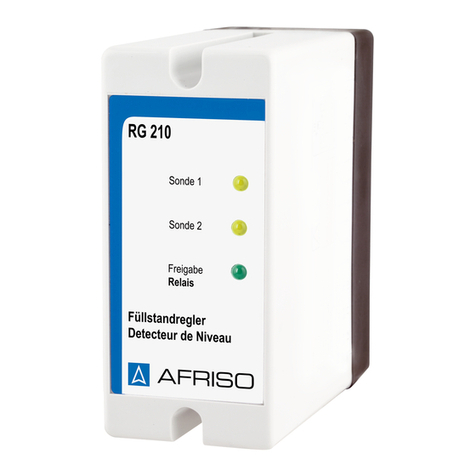
AFRISO RG 210 User manual

AFRISO

AFRISO RG 210 User manual

AFRISO RG 210 User manual

AFRISO

AFRISO RG 210 User manual

AFRISO CosiTherm WB 10 D8-230 User manual

AFRISO

AFRISO CosiTherm WB 10 D8-230 User manual

AFRISO ProCalida CC 1 User manual

AFRISO

AFRISO ProCalida CC 1 User manual

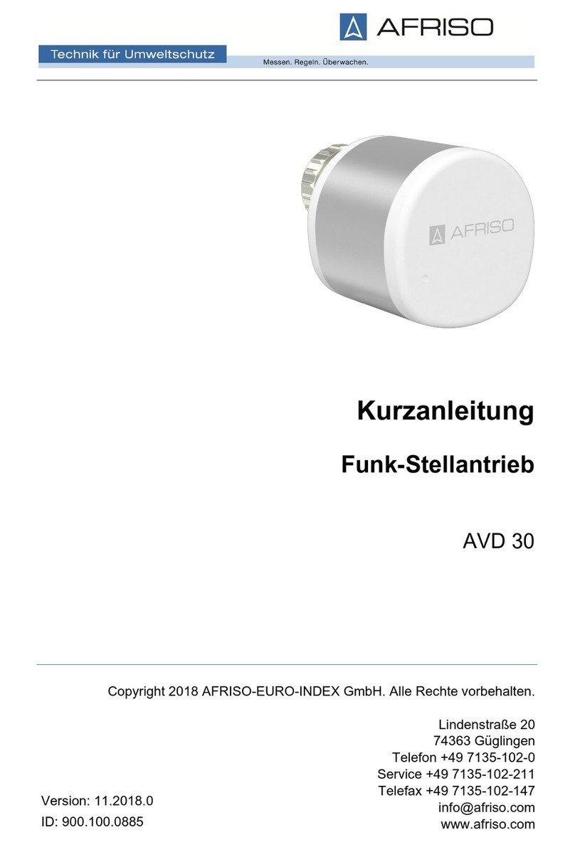
AFRISO AVD 30 User manual

AFRISO

AFRISO AVD 30 User manual

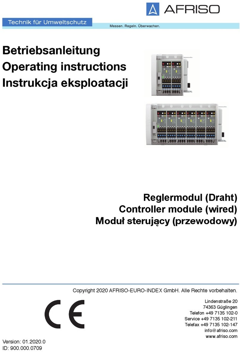
AFRISO ARM ProClick User manual

AFRISO

AFRISO ARM ProClick User manual

Popular Controllers manuals by other brands

Kohler GM35950 Replacement

Kohler

Kohler GM35950 Replacement

Omron E5AN user manual

Omron

Omron E5AN user manual

GE ASTAT XL Series Testing, troubleshooting and servicing instructions

GE

GE ASTAT XL Series Testing, troubleshooting and servicing instructions

PPI HumiTherm Plus user manual

PPI

PPI HumiTherm Plus user manual

Blichmann Engineering Power Controller 120VAC Assembly operation maintenance

Blichmann Engineering

Blichmann Engineering Power Controller 120VAC Assembly operation maintenance

OEZ MP-BD Series Instructions for use

OEZ

OEZ MP-BD Series Instructions for use

Emerson E2 user manual

Emerson

Emerson E2 user manual

ABB ACS320 series user manual

ABB

ABB ACS320 series user manual

HP HSG80 - StorageWorks RAID Array Controller Maintenance and service guide

HP

HP HSG80 - StorageWorks RAID Array Controller Maintenance and service guide

Festo CMMP-AS-***-M3 Series Description

Festo

Festo CMMP-AS-***-M3 Series Description

Danfoss EvoFlat WSS installation guide

Danfoss

Danfoss EvoFlat WSS installation guide

Hydra 120 Operation manual

Hydra

Hydra 120 Operation manual

CLA-VAL CF1 Series Installation operation & maintenance

CLA-VAL

CLA-VAL CF1 Series Installation operation & maintenance

Honeywell CN100 Planning and installation guide

Honeywell

Honeywell CN100 Planning and installation guide

BECS BECSys7 230VAC Operation and maintenance manual

BECS

BECS BECSys7 230VAC Operation and maintenance manual

CEBEK I-16 quick start guide

CEBEK

CEBEK I-16 quick start guide

Mitsubishi Electric NZ2GN2S1-16D user manual

Mitsubishi Electric

Mitsubishi Electric NZ2GN2S1-16D user manual

REMEHA Celcia 20 FUNCTIONS

REMEHA

REMEHA Celcia 20 FUNCTIONS

manuals.online logo
manuals.online logoBrands
  • About & Mission
  • Contact us
  • Privacy Policy
  • Terms and Conditions

Copyright 2025 Manuals.Online. All Rights Reserved.