AgLand Macerator 6620 User manual

Operator’s Manual
June 2009
Macerator 6620
Macerator 6620
2009

Replacement Parts
To obtain prompt, effi cient service, give the dealer the following
information.
1. Correct stock number.
2. Model number of the machine.
3. Serial number of the machine.
The serial number is important in identifying your machine. It
contains information for ordering replacement parts and op-
tions which may vary depending on the serial number identi-
fi cation.
Measurements are given in U.S. units followed by the equiva-
lent in metric units. Hardware sizes are given in inches for U.S.
hardware and millimeters for metric hardware.
All nuts and bolts are specifi ed in Grade 5 unless otherwise
indicated.
Serial # on plate inside right side cover.
Box 479 Arborg MB, R0C 0A0
Macerator 6620
Made in Canada
Model #:
Serial #:

1
Contents
Warranty Registration Form
............................................................................................................................................
3
Introduction
.......................................................................................................................................................................
5
Safety
............................................................................................................................................................................
6–7
Transport Safety
....................................................................................................................................................................................
6
Operating Safety
....................................................................................................................................................................................
Operating Safety .................................................................................................................................................................................... Operating Safety
7
Hydraulic Safety
.....................................................................................................................................................................................
7
Air Safety
................................................................................................................................................................................................
Air Safety ................................................................................................................................................................................................ Air Safety
7
Safety Decals
....................................................................................................................................................................
8
Specifi cations
...................................................................................................................................................................
9
Assembly
.........................................................................................................................................................................
10
Assembly (Attachments)
.........................................................................................................................................
11–13
Moldboard Merger
...............................................................................................................................................................................
11
Spreader
..............................................................................................................................................................................................
12
Windrower
............................................................................................................................................................................................
13
Tedder
...........................................................................................................................................................................................
14–15
Tedder Hydraulics
.........................................................................................................................................................................
16–17
Field Set Up
..............................................................................................................................................................
18–19
PTO Speed
...........................................................................................................................................................................................
18
Pickup Height and Adjustment
...........................................................................................................................................................
18
Steel Roll Adjustment
..........................................................................................................................................................................
18
Preparation (Air System)
.....................................................................................................................................................................
19
Rubber Roll Pressure Adjustment
......................................................................................................................................................
19
Steel Roll Pressure Adjustment
..........................................................................................................................................................
19
Maintenance
............................................................................................................................................................
20–23
Checklist
..............................................................................................................................................................................................
20
Roll Drive Belt Replacement
...............................................................................................................................................................
21
Bearing Replacement
.........................................................................................................................................................................
22
Replacing or Repacking Wheel Bearings
...........................................................................................................................................
22
Pickup Teeth, Wrappers, and Wear Strips
.........................................................................................................................................
22
Inch Torque Chart for Bolts and Nuts
.................................................................................................................................................
23
Metric Torque Chart for Bolts and Nuts
.............................................................................................................................................
23
Lubrication
......................................................................................................................................................................
24
Belts
.................................................................................................................................................................................
25
Optional Kits
....................................................................................................................................................................
26
Troubleshooting
..............................................................................................................................................................
27
Warranty
...........................................................................................................................................................
Back Cover


I have instructed the buyer on the above described equipment and included a review of the Operator’s Manual, assembly,
maintenance, safety, and applicable warranty policy.
Dealer’s Signature Date
The above equipment and the Operator’s Manual have been received by me and I have been instructed as to the care, ad-
justments, safe operation, and applicable warranty policy.
Purchaser’s Signature Date
Customer Name:
Address:
City:
Prov/State: Postal/Zip:
Phone No:
Model No:
Serial No:
Dealer:
Address:
City:
Prov/State: Postal/Zip:
Phone No:
Date Purchased:
Check One: Commercial Use Farm Use
Prov/State: Postal/Zip:
Prov/State: Postal/Zip:
AgLand Macerator 6620™
LIMITED WARRANTY REGISTRATION FORM
The Macerator 6620 is warranted by AgLand to the original purchaser, to be free of defects in workmanship and material for
a period of one (1) year from date of purchase for farm use
(three (3) months from date of purchase for commercial use)
.
AgLand does not warrant any damage caused by negligence, modifi cations, and/or lack of maintenance (see Maintenance
Schedule in Operator’s Manual).
AgLand will not be liable for the cost of shipping or any other cost incurred for replacement or repair of any parts. AgLand is not
liable for any accidents which may occur from or during the operation of the Macerator 6620, or damage incurred due to Mac-
erator failure. The purchaser assumes all responsibility for the operation, care, maintenance, and safety.
See back of the Operator’s Manual for complete warranty details.
Failure to return completed registration form to AgLand within thirty (30) days of delivery will VOID the warranty.
This form must be fi lled out by the dealer and signed.
Mail to:
AgLand Industries Inc.
Box 479, Arborg, MB
R0C 0A0
Check One: Commercial Use Farm Use
Check One: Commercial Use Farm Use
DEALER CHECKLIST
Belt tension checked and adjusted per Manual Specs
Pickup, including fi nger height, adjusted and set
Air lines and airbags checked for leaks
Hydraulic lines and fi ttings checked for oil leakage
Main and gear box drive shaft coupler set screws checked
and tight
All refl ectors in place
Wheel bolts tight
Tire air pressure (20 PSI maximum (138 kPa))
All grease fi ttings greased
All safety procedures have been reviewed with customer
Rubber and steel rolls, including spacing, checked and
adjusted
All warning decals are in place, clean, and legible
Customer has been instructed to review safety and operat-
ing procedures with all operators annually
Belt tension checked and adjusted per Manual Specs
Pickup, including fi nger height, adjusted and set
Air lines and airbags checked for leaks
Wheel bolts tight
All refl ectors in place
Main and gear box drive shaft coupler set screws checked
Customer has been instructed to review safety and operat-
All grease fi ttings greased
All safety procedures have been reviewed with customer
Rubber and steel rolls, including spacing, checked and
All warning decals are in place, clean, and legible
I have thoroughly inspected the machine and made adjustments and corrections as needed.
Inspected By Signature Date
Hydraulic lines and fi ttings checked for oil leakage
White - AgLand Yellow - Customer Pink - Dealer


5
AgLand Industries Inc.
is a Canadian owned and oper-
ated company located in central Canada, in the province
of Manitoba. AgLand was founded in 2001 by a group of
innovative entrepreneurs that transformed their ideas
and expertise into a leading manufacturing company of
agricultural crop equipment.
Box 479, Arborg MB, Canada R0C 0A0
Tel: 204.364.2211
Fax: 204.364.2472
Email: [email protected]
Web: www.aglandindustries.com
Introduction
The Macerator is designed to condition hay for a super
fast dry down while maintaining the maximum amount of
nutrients and color. The Macerator utilizes special steel
rolls, each running at a different speed allowing for a mea-
sured nicking of the stem for greater air exposure. The low
profi le, heavy duty pickup allows for rapid operation with
minimal leaf loss.
The roll system of the Macerator is designed to allow for the
right amount of maceration without cutting up the hay.
These operating and maintenance instructions have been
compiled from extensive fi eld experience and engineering
data. Some information is general in nature due to un-
known and varying conditions. However, through experi-
ence and these instructions, you will be able to develop
operating procedures suitable to your particular situation.
Please study this manual from the beginning to end BE-
FORE operating your new Macerator 6620. Pay special
attention to the Safety section in this manual and the
safety cautions on your equipment. Should anyone else
operate this equipment be sure that they understand
ALL safety, operating, and maintenance information pre-
sented in this manual.
The terms ‘right’ and ‘left’ as used throughout this manu-
al, are determined by facing the direction the machine will
travel when in use.
The photographs, illustrations, and data used in this man-
ual were current at the time of printing, but due to pos-
sible inline production changes, your machine can vary
slightly in detail. The Manufacturer reserves the right to
redesign and change the machine as necessary without
notifi cation.
WARNING
Some pictures in this manual show the machine with
shields removed to allow for a better view of the sub-
ject. The machine must never be operated with any of
the shields removed.
Congratulations, you have just purchased the new and improved AgLand Macerator 6620. To get the maximum
benefi t from your Macerator we suggest that you read this manual carefully.
6
Read this manual completely and understand all oper-
ating instructions and precautions BEFORE attempting
to operate or service your machine.
The safety information given in this manual does not re-
place safety codes, insurance needs, or state/province
and local laws. Make sure your machine has the correct
equipment needed as specifi ed by the local laws and reg-
ulations.
Understand that your safety and the safety of others is
measured by how you service and operate this machine.
IMPORTANT!
Review and understand the positions and
functions of all machine controls before operating this
machine.
WARNING! Do NOT attempt any adjustments, mainte-
nance, troubleshooting, or repairs while machine com-
ponents are moving or activated with pressure.
▪ Lower machine to ground or onto appropriate blocks.
▪ Stop tractor engine and remove ignition key.
▪ Set tractor parking brake prior to leaving operator sta-
tion.
Safety Alert Symbol
The Safety Alert symbol identifi es impor-
tant safety messages in the manual and on
the machine. When you see this symbol, be
alert to the possibility of personal injury or
death. Follow all instructions in the safety
message given. This symbol means atten-
tion, be alert, and your safety is involved.
Three Reasons To Follow Safety Instructions:
1. Accidents disable and kill.
2. Accidents cost.
3. Accidents can be avoided.
Slow Moving Vehicle Emblem
The Slow Moving Vehicle (SMV) emblem
must be placed on the rear of the ma-
chine and be visible to traffi c approach-
ing the machine from the rear while
traveling on public roads. Keep the SMV
emblem clean and replace when dam-
aged or emblem materials have faded. The SMV should
only be displayed on the machine at road speeds less
than 25 MPH (40 km/h).
Safety
▪ The operator is responsible for complying with all
local regulations regarding transporting agricultural
equipment on public roads and highways.
▪ Ensure all lights and refl ectors, as required by local
law, are in place, intact, and clean before transport-
ing machine on public roads and highways.
▪ Connect electrical socket on machine wiring har-
ness to tractor receptacle.
▪ Ensure SMV emblem is clean and properly displayed,
where required by law, before transporting machine
on public roads and highways.
▪ Do NOT allow riders on machine at any time, includ-
ing transport of machine on public roads and high-
ways.
▪ Maximum transport speed is 20 MPH (32 km/h).
Reduce speed on rough roads and surfaces.
▪ Use proper retainer on drawbar hitch pin and attach
safety tow chain to tractor prior to transporting ma-
chine on public roads and highways.
▪ Ensure that travel lock pin is installed and secured
in the hole provided for transport.
▪ Tractor light switches should be set for road trans-
port. Refer to tractor operator’s manual for infor-
mation.
Transport Safety
DANGER
DANGER:
Indicates an imminently hazardous situation
that, if not avoided, WILL result in death or serious injury
if proper precautions are not taken.
Signal Words
WARNING:
Indicates a potentially hazardous situation
that, if not avoided, COULD result in death or serious in-
jury if proper precautions are not taken.
CAUTION:
Indicates a potentially hazardous situation that,
if not avoided, MAY result in minor or moderate injury if
proper practices are not taken, or serves as a reminder to
follow appropriate safety practices.
CAUTION
WARNING

7
Safety
Operating Safety
▪ Ensure that all components in the hydraulic system
are kept in good condition.
▪ Replace any worn, cut, abraded, fl attened, or
crimped hoses and/or metal lines.
▪ Do not attempt any poorly executed repairs to hy-
draulic lines, fi ttings, or hoses by using tape, clamps,
or cements. The hydraulic system operates under
extremely high pressure: 1600 to 2300 PSI (11,033
to 15,859 kPa). Such repair will fail suddenly and
create unsafe conditions.
▪ Wear proper hand and face protection (e.g. face
shield) when searching for a high pressure hydraulic
leak. Use a piece of wood or cardboard as a back-
drop instead of hands. A high pressure concentrated
stream of hydraulic fl uid can pierce the skin. If such
happens, seek immediate medical attention as in-
fection and toxic reaction could develop.
▪ Before applying hydraulic pressure to the system,
make sure all connections are tight and that lines,
hoses, and couplings are not damaged.
Think Safety,
Work Safely!
▪ REVIEW ALL SAFETY INSTRUCTIONS with all opera-
tors before allowing them to operate the equipment.
Review instructions at least once each year.
▪ All shields and guards must be intact and in po-
sition and securely fastened before operating the
Macerator.
▪ Only use a tractor equipped with ROPS cab and seat
belt. Use caution when operating close to a road or
building, the machine can throw stones and other
objects during operation.
▪ Emphasize the importance of safety when working
around and operating the machine.
▪ Do NOT allow riders on any part of the equipment at
any time.
▪ Always keep hands, feet, and clothing away from
moving parts.
▪ Always lower the Macerator to the ground when
parking.
▪ Use transport lock pin and retainer to secure the
lift linkage of the Macerator before transporting
equipment.
▪ Use safety tow chain at all times.
▪ NEVER attempt to unplug the machine when the trac-
tor is running and hydraulic system is pressurized.
▪ Keep hands, feet, and clothing away from the pickup
area when in operation to avoid entanglement haz-
ards. Do not open or remove shields or guards while
machine is running.
▪ Relieve all pressure from hydraulic lines before dis-
connecting them. Before applying pressure to the
system, make sure all connections are tight and
that hoses and lines have not been damaged.
Hydraulic Safety
▪ Make sure all hoses and bellows are kept in good
condition and are clean.
▪ Replace any damaged lines or bellows.
▪ Do not exceed 120 PSI (827 kPa) air pressure in
tank and 100 PSI (689 kPa) in air bags.
Air Safety
Hitch and safety chain.
Travel lock pin in place.
Keep the Operator’s Manual
in the storage container pro-
vided on the Macerator. The
Operator’s Manual must be
available for use by all op-
erators.
Operator’s Manual Storage Container

8
Safety Decals
Moving Parts Hazard
High Pressure Fluid Hazard
Keep Shields and Guards in Place

9
Specifi cations
Dimensions
Overall Width 10’6” (3.20 m)
Length 11’4” (3.45 m)
Height operation 3’6” (1.07 m)
transport 5’6” (1.68 m)
Weight (with windrower) 4,334 lbs. (1966 kg)
Tires (4)
Tire Size 11 L - 15 SL
Pressure 20 PSI (138 kPa)
Wheel Hub 6 bolt
Wheel Bolt Torque 85 ft-lbs (115.3 Nm)
Pickup
Width 5’6” (1.68 m)
Clearance* 14” to 16” (35.6 cm to 40.6 cm)
Tooth Clearance** 10” to 12” (24.5 cm to 30.5 cm)
Pickup Tooth Spacing 2.75” (7 cm)
* Under pickup when raised.
** When raised.
Rolls
Width of rubber feed rolls 5’6” (1.68 m)
RPM of rubber feed rolls 645 RPM
Minimum space between rubber rolls 1/32” (0.8 mm)
Width of steel rolls 5’6” (1.68 m)
RPM of top steel roll 1372 RPM
RPM of bottom steel roll 1514 RPM
Minimum space between steel rolls 1/32” (0.8 mm)
Tractor Requirements
Suggested tractor size* Min. 80 HP - Max. 120 HP
(Min. 60 kW - Max. 89 kW)
Suggested min. under frame clearance** 15” (38 cm)
* Tractor should be of suffi cient size to maintain operator
control in all situations.
** To allow swath to fl ow freely under tractor.
AgLand Macerator
Model 6620
Air System
Size of air pressure tank 12 US Gallon (45 L)
Maximum air pressure in tank 120 PSI (827.4 kPa)
Hydraulic outlets required 1
Operating Speed
Approximate range* 5 to 10 MPH (8 to 16 km/h)
*Depending on crop conditions.
Swath Size
Maximum Width 5’ (1.52 m)
Cut Width
Recommended Width 14’ to 16’ (4.27 m to 4.88 m)
Capacity
Maximum 5.0 ton/acre (11.4 tonne/hectare)
Lubrication
NGLI No. 2 multi-purpose high temperature lithium base
grease
Gear Box
SAE15W40 (Diesel Motor Oil) 2.6 US qt. (2.5 L)
Some weights and measurements are approximate.
All specifi cations, statements, and information shown in
this manual are believed to be accurate at the time of print-
ing. Specifi cations are subject to change without notice.
10
Assembly
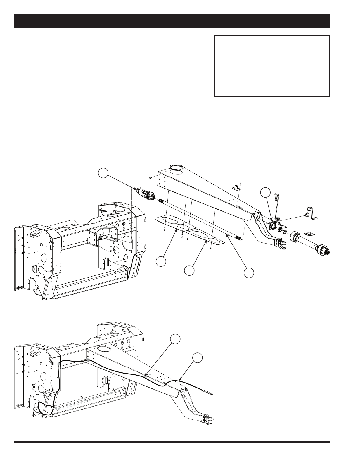
Attaching Hitch
Sometimes the hitch will be shipped detached from the
unit to allow for a more compact shipping package.
1. Bolt hitch to main frame, Figure 1, using fourteen
5/8” x 1-1/2” carriage bolts. Ensure all bolts are se-
curely tightened.
2. Remove bearing on front of hitch (C), slide drive
shaft (B) onto override clutch (A) through front bear-
ing hole. Reinstall bearing and tighten shaft bolts on
override clutch (A).
3. Install the long hydraulic hose (G) securely with the
clamps (F) provided, as shown in Figure 2.
4. Torque required on 5/8” bolt for overriding clutch (A)
is 65 ft-lbs (88.1 Nm).
A. Override Clutch
B. Drive Shaft
C. Front Hitch Bearing
D. A Frame Cover (Back)
E. A Frame Cover (Front)
F. Hose Clamp
G. Long Hydraulic Hose
Figure 1
Figure 2
C
D
E
B
A
G
F
11
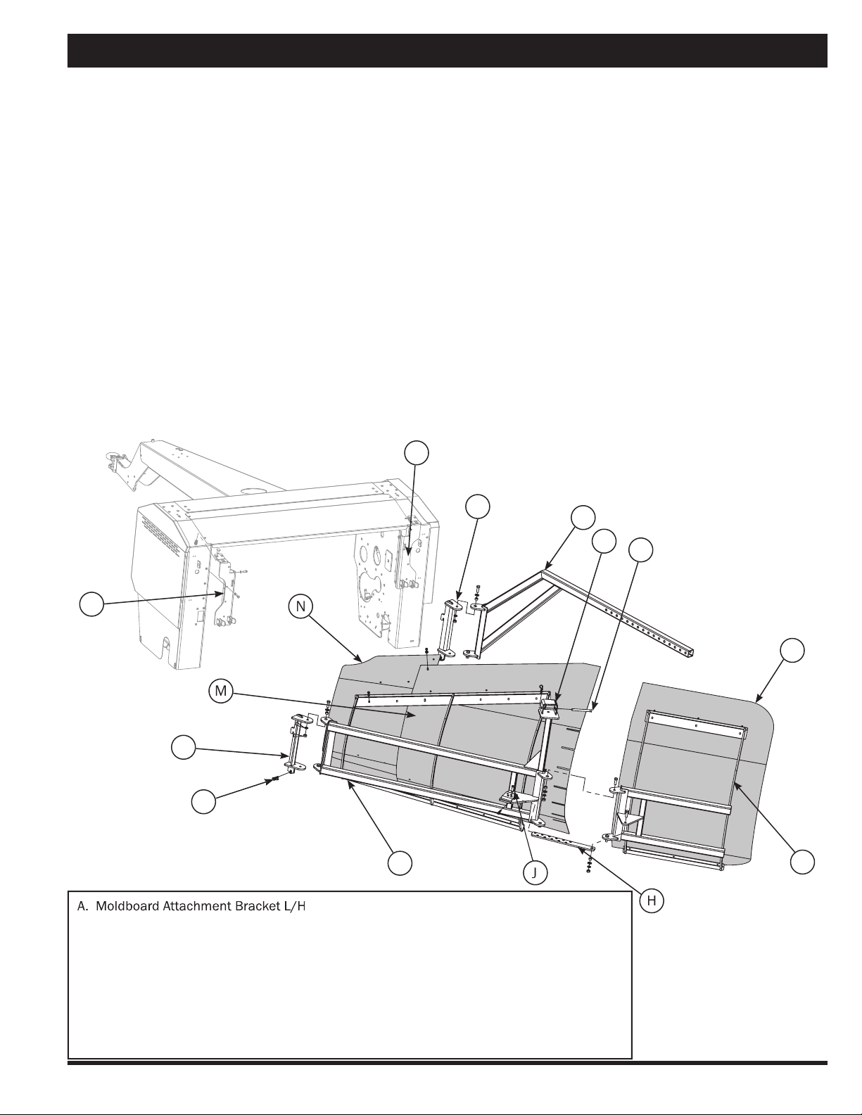
A. Moldboard Attachment Bracket L/H
B. Moldboard Main Frame
C. Quick Attach Bracket L/H
D. Adjustment Bar
E. Moldboard Attachment Bracket R/H
F. Quick Attach Bracket R/H
G. Small Frame
H. Extension Adjustment Bar
J. Adjustment Pin
K. Pin
L. Short Moldboard Sheet
M. Long Moldboard Sheet
N. Small Moldboard Sheet
O. Lynch Pin
P. Adjustment Bracket
Assembly (Attachments)
1. Attach left hand (L/H) moldboard attachment brack-
et (A) to the moldboard main frame (B) and attach
main frame to quick attach bracket (C - already in-
stalled) and insert lynch pin (O).
2. Attach right hand (R/H) moldboard attachment bracket
(E) to the adjustment bar (D) and attach bar to bracket
(F - already installed) and insert lynch pin (O).
3. Attach small frame (G) to the main frame (B), using
1/2” x 1-1/2” hex bolts with bushings, washers, lock
washers, and hex nuts.
4. Attach extension adjustment bar (H) to small frame
(G) using 1/2” x 1-1/2” standard bolt, bushing,
washer, lock washer and standard nut and insert ad-
juster pin (J).
5. Slide main frame adjustment bar (D) through the ad-
justment bracket (P) and insert 1/2” x 4-1/2” pin (K).
Moldboard Sheet Installation
6. Install short moldboard (L) to outside portion of small
frame (G) using 5/16” x 3/4” carriage bolts and hex
nuts.
7. Install long moldboard sheet (M) onto the main
frame (B) using 5/16” x 3/4” carriage bolts, overlap-
ping the short moldboard sheet.
8. All bolts holding the moldboard sheets can now be
fully tightened.
9. Adjust angle of moldboard by moving adjustment bar
(D) in or out of adjustment bracket (P) to preferred
moldboard angle and insert 1/2” x 4-1/2” pin. A
tighter angle will result in less inversion. A wider an-
gle will result in a greater inversion.
Moldboard Merger
Moldboard Attachment
N
A
M
C
D
F
E
K
L
H
B
G
O
P
12
Assembly (Attachments)
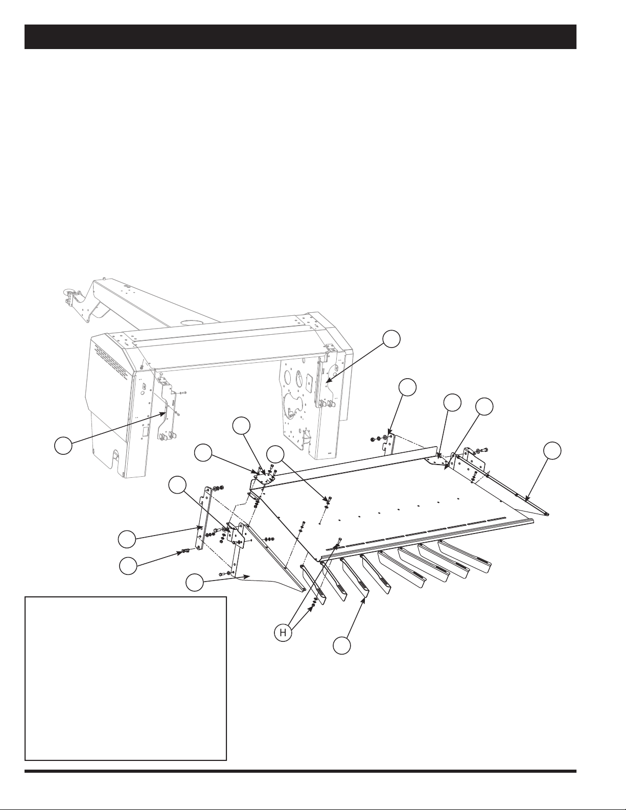
Spreader Attachment
The spreader attachment allows the Macerator to spread
a wider swath and leave a thinner layer on the fi eld for
greater sun and wind exposure.
The spreader attachment attaches to the rear of the main
frame.
1. Attach bracket (A) to the side panels (C and D) using
3/8” x 1-1/4” bolts with washers, lock washers, and
nuts.
2. Mount side panels (C and D) to top plate (B) with
5/16” x 3/4” bolts, washers, and lock washers.
3. Assemble reinforcement plates and brackets (K)
with hardware bolts, nuts and washers (L).
Spreader Attachment
A. Quick Mounting Bracket
B. Top Plate
C. Side Panel
D. Side Panel
E. Quick Mounting Bracket (on main frame)
F. Defl ector Fin
G. Bolt
H. Nuts and Washers
J. Lynch Pins
K. Reinforcement Plates and Brackets
L. Bolt, Nut and Washer
B
A
E
D
F
C
A
G
E
J
4. Mount defl ector fi ns (F) to top plate (B) using 3/8”
x 3/4” bolts (G) and washers, lock washers, and
nuts (H).
5. Hook spreader attachment to the quick mounting
brackets (E - on main frame) and insert lynch pin (J).
K
K
K
L
H

13
A
B
D
H
C
J
L
E
K
D
M
L
G
Assembly (Attachments)
Windrower Attachment
The windrower attachment allows you to direct the cut hay
down to keep a tighter narrow windrow, or up for a wider
swath width.
1. Insert 3/8” x 1-1/4” bolts through side panel (A and
K) and attach quick mounting bracket (B) to both
side panels.
2. Mount side panels (A and K) to top plate (G) with
5/16” x 3/4” bolts. Do not tighten bolts.
3. Assemble reinforcement plates (O) with hardware
bolts, nuts and washers (P).
4. Mount side bracket (C) to panel (A) with 3/8” x 3/4”
bolts. Only two bolts.
5. Insert windrow baffl e (E) into hole of side bracket (C).
6. Mount the other side bracket (F) to side panel (K)
with 3/8” x 3/4” bolts.
7. Mount adjustment bracket (H) using 5/16” x 1-1/2”
socket head cap screws and wing bolts (D).
8. Install left and right side width adjusters (J and M)
using 3/8” x 1” bolt and bushing (L) through top
plate (G).
9. Insert wing bolt (D) with washer through slot into
width adjusters (J and M).
10. Tighten all bolts evenly.
11. Hook spreader attachment to the quick mounting
bracket on main frame and insert lynch pin (N).
A. Side Panel
B. Quick Mounting Bracket
C. Left Side Bracket
D. Wing Bolt
E. Windrow Baffl e
F. Right Side Bracket
G. Top Plate
H. Adjustment Bracket
J. Width Adjuster
K. Side Panel
L. Bushing
M. Width Adjuster
N. Lynch Pin
O. Reinforcement Plates
P. Bolt, Nut and Washer
Note:
Use supplied washers and
nuts with described bolts
above.
Windrower Attachment
N
P
O
O
O

14
Assembly (Attachments)
Item No.
Stock No.
Description
Qty.
1
800165
Bolt, Standard, NC, 1/2” x 1-1/2”
20
2
800166
Bolt, Standard, NC, 1/2” x 1-1/4”
4
3
800167
Bolt, Standard, NC, 1/2” x 1-3/4”
8
4
800190
Bolt, Standard, NC, 3/4” x 2”
4
5
800191
Bolt, Standard, NC, 3/4” x 2-1/2”
1
6
800233
Nut, Standard, NC, 1/4”
10
Tedder Attachment
35
41
9
3
16
20
4
31
8
40
19
3
2
5
18
17
6
43
33
38
14 12
44
13
11
11
13
12
14
22
24
28
27
29
23
28
28
28
30 10
34
45
42
29
26
49
1
46
13
48
22
47
36
27
25
26
21
32
33
13
33
16
11
13
50
3
15
13
11
39
13 11
7
12
37

15
Assembly (Attachments)
Item No.
Stock No.
Description
Qty.
7
800321
Coupler, 1-3/8”
1
8
801682
Tedder, Daros (Rossi)
1
9
801818
Pin, Lynch, 7/16”
2
10
801820
Pin, Hitch, R, 1/8” x 2-5/8”
1
11
804196
Nut, Standard, NC, 1/2”
36
12
804199
Nut, Standard, NC, 3/4”
5
13
804367
Washer, Lock, Spring, 1/2” Gr. 8
40
14
804369
Washer, Lock, 3/4”
4
15
807524
Washer, SAE, 1/2”
2
16
807706
Bolt, Carriage, NC, 1/2” x 1-3/4”
6
17
808353
Washer, Lock, Spring, 1/4” Gr. 8
10
18
808781
Washer, Flat, 1/4” SAE
10
19
808782
Bolt, Standard, NC, 1/4” x 2”
10
20
808784
Bolt, Standard, NC, 1/2” x 2-1/4” Gr. 8
2
21
808785
Motor, Hydraulic, 2001 DH 50
1
22
809040
Bolt, Standard, Metric, 10 x 1.5 x 40, Gr. 8.8
6
23
809090
Tooth Arm, Fixed, Tedder
8
24
809091
Tooth, Tedder
12
25
809092
Plate, Tooth Clamp, Tedder
12
26
809094
Bolt, Standard, Metric, 14 x 2.0 x 40, Gr. 8.8
20
27
809095
Nut, Standard, Lock, Nylon Insert, Metric, 14 x 2.0 Gr. 8.8
24
28
809096
Tooth Arm, Adjustable, Tedder
4
29
809098
Bolt, Standard, Metric, 14 x 2.0 x 25, Gr. 8.8
4
30
809586
Pin, Clevis, 3/4” x 2”
1
31
812755
Bolt, Standard, NC, 7/8” x 4-1/2”
2
32
812756
Nut, Standard, NC, 7/8”
4
33
812757
Washer, SAE, 7/8”
6
34
810158
Turnbuckle Assembly, Tedder
1
35
810553
Hook, Attachment, L/H, Tedder
1
36
810555
Hook, Attachment, R/H, Tedder
1
37
807861
Arm, Motor Mounting, R/H
1
38
807864
Arm, Motor Mounting, L/H
1
39
807859
Motor Mounting Plate
1
40
807882
Tedder Flap
2
41
807876
Tedder Main Beam
1
42
810559
Tedder Flap Frame, L/H
1
43
810562
Tedder Flap Frame, R/H
1
44
810557
Arm, Tedder
2
45
810157
Bushing, Turnbuckle, Tedder
1
46
813960
Clamp, Tedder
5
47
813968
Bracket, Attachment, Tedder
3
48
813970
Clamp, Bracket, Flap Attach, L/H, Tedder
1
49
813972
Clamp, Bracket, Flap Attach, R/H, Tedder
1
50
814677
Stabilizer Bar, Tedder
2
Tedder Attachment
16
Assembly (Attachments)
2
10
16 18
17
1
15
15
14
9
9
14
Arrow
Up
4
5
5
3
12
6
8
13
11
7
7
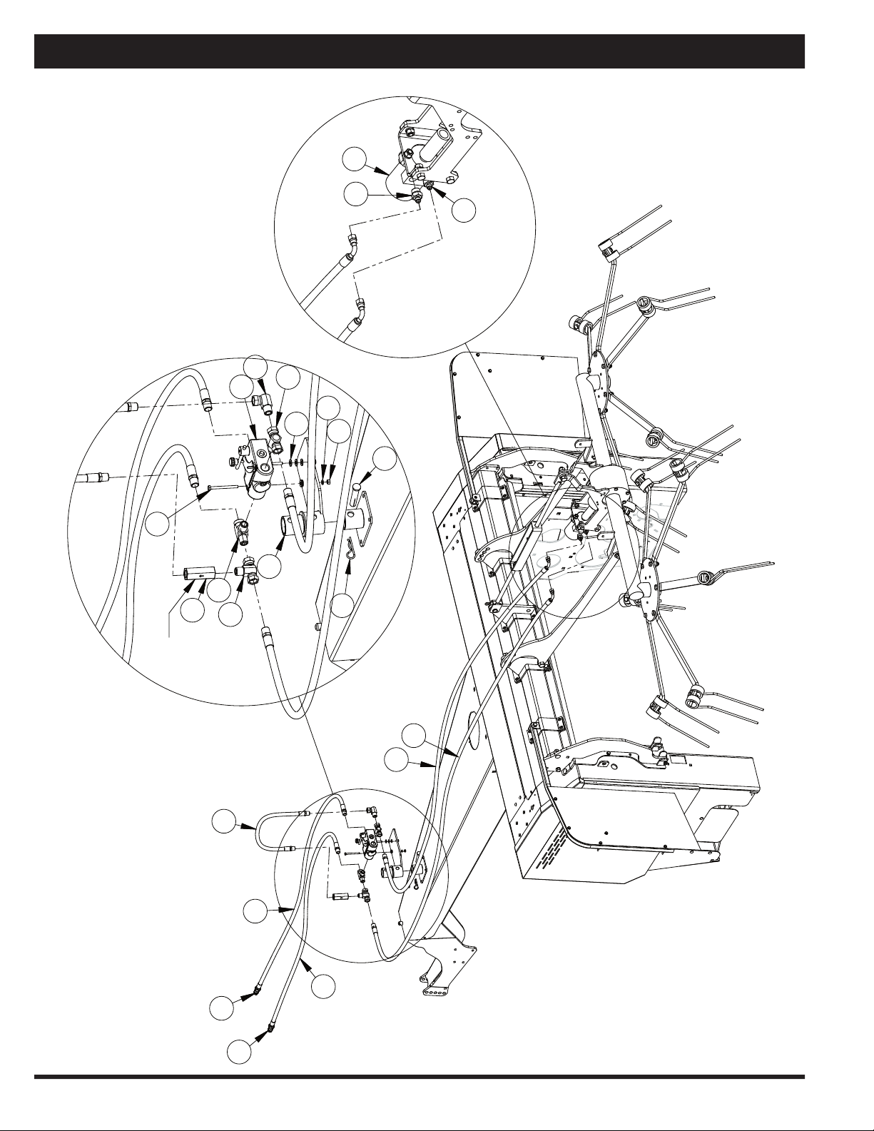
Tedder Attachment Hydraulics

17
Assembly (Attachments)
Item No.
Stock No.
Description
Qty.
1
802478
Hydraulic Hose, 24"
1
2
801820
Pin, R, 1/8"
1
3
802474
Valve, Check
1
4
802482
Elbow, Hydraulic
1
5
802484
Tee, Hydraulic
2
6
802485
Tee, Hydraulic
1
7
802486
Adapter, Hydraulic
2
8
802836
Valve Body
1
9
804099
Quick Coupler
2
10
807055
Pin, Clevis
1
11
808785
Motor, Hydraulic, 2001 DH 50
1
12
808783
1/4" x 3" Bolt, Standard
2
13
807879
Valve Body Holder
1
14
808721
Hydraulic Hose
2
15
808722
Hydraulic Hose
2
16
800233
1/4" Nut, Standard
2
17
807522
5/16" SAE Washer, Flat
6
18
808353
1/4" Washer, Lock
2
Tedder Attachment Hydraulics
18
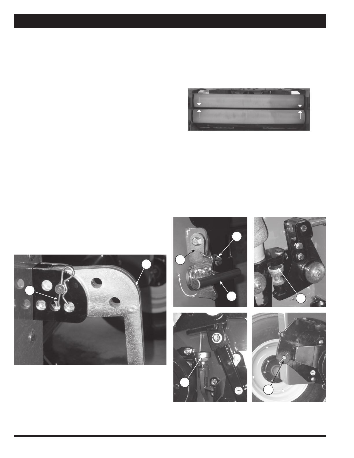
1. Raise the Macerator using the hydraulics.
2. Turn crank (A) clockwise to widen the gap or counter-
clockwise to narrow the gap. 1/2 turn = .02” (0.5
mm). For a better fi ne tune, adjust bolt (D).
3. Ensure to set the gap exactly the same on both sides,
using a gauge.
4. Put crank lock (B) in place and secure with pin (C).
5. To ensure that the rolls do not touch, the safety stop
is set by the factory at 1/32” or .8 mm.
6. If the safety stop (E) needs adjusting put the travel
pin (F) in place while unit is raised.
7. Adjust the safety stop bolt (E) as needed. Ensure the
rolls do not touch during operation.
8. Repeat steps 1–7 to fi ne tune if necessary.
Field Set Up
Use with a tractor having a minimum of 80 HP (60 kW).
Tractor should have suffi cient ground clearance for
swath to pass cleanly under it.
PTO Speed
Unless otherwise specifi ed, units are shipped with 1000
PTO speed. Units with 540 RPM PTO are also available.
Contact your dealer for more information.
The PTO should be run at approximately 1000 RPM. The
front rubber rolls run at 645 RPM and the bottom steel
roll runs at 1514 RPM at a tractor PTO speed of 1000.
The upper steel roll runs at 1372 RPM at 1000 tractor
PTO speed.
Pickup Height & Adjustment
The Macerator 6620 pickup should be adjusted so that
it will cleanly pick up all material off of the fi eld without
gouging the soil. The height may need resetting in order
to arrive at the best working height.
1. If the pickup is too low to the ground use the tractor
hydraulic cylinder control to raise the pickup.
2. Remove pin (A) and slide adjuster bar (B) to desired
height. Pushing bar in raises machine, and pulling
the bar out lowers the machine.
3. Reinsert pin and lock in place.
Gap Gap
Steel Roll Adjustment
For best results adjust the Macerator 6620 for your specif-
ic fi eld conditions. The smaller the gap between the steel
serrated rolls, the more aggressive the maceration of the
hay will be. Both the space between the rolls and the air
pressure need to be adjusted for maximum effi ciency.
A
B
B
A
C
D
F
E
Table of contents
Other AgLand Farm Equipment manuals


