AgLand MACERATOR 6610 User manual
TM
Operator’s Manual 2004
MACERATOR 6610

Replacement Parts
To obtain prompt, effi cient service, always remember to
give the dealer the following information.
1. Correct part description.
2. Model number of the machine.
3. Serial number of the machine.
The serial number is important in identifying your ma-
chine. It contains information for ordering replacement
parts and options which may vary depending on the serial
number identifi cation.
Measurements are given in U.S. units followed by the
equivalent in metric units. Hardware sizes are given in
inches for the U.S. hardware and millimeters for the met-
ric hardware.
Contents
Warranty Registration Form
..............................................................................................................................................
2
Introduction
..........................................................................................................................................................................
4
Safety
................................................................................................................................................................................
Safety ................................................................................................................................................................................Safety
5
–
6
Transport Safety
....................................................................................................................................................................................
Transport Safety ....................................................................................................................................................................................Transport Safety
5
Operating Safety
....................................................................................................................................................................................
6
Hydraulic Safety
.....................................................................................................................................................................................
Hydraulic Safety ..................................................................................................................................................................................... Hydraulic Safety
6
Air Safety
................................................................................................................................................................................................
6
Sp
ecifi cations
.......................................................................................................................................................................
7
Assembly
...............................................................................................................................................................................
Assembly ...............................................................................................................................................................................Assembly
8
Assembly (attachments)
.............................................................................................................................................
9
–11
Swath Inverter
.......................................................................................................................................................................................
9
Spreader
..............................................................................................................................................................................................
10
Windrower
............................................................................................................................................................................................
1
1
Field Setup
..................................................................................................................................................................
1
2
–13
PTO Speed
...........................................................................................................................................................................................
1
2
Pickup Height and Adjustment
...........................................................................................................................................................
12
Steel Roll Adjustment
..........................................................................................................................................................................
12
Pr
eparation (Air System)
.....................................................................................................................................................................
13
Rubber Roll Press
ure Adjustment
......................................................................................................................................................
13
Steel Roll P
ressure Adjustment
..........................................................................................................................................................
1
3
Maintenance
...............................................................................................................................................................
14–16
Checklist
..............................................................................................................................................................................................
14
Roll Drive Belt Replacement
...............................................................................................................................................................
15
Bearing Replacement
.........................................................................................................................................................................
16
Replacing or Repacking Wheel Bearings
...........................................................................................................................................
16
Pickup Teeth, Wrappers, and Wear Strips
.........................................................................................................................................
1
6
Lubrication
.........................................................................................................................................................................
1
7
Trouble Shooting
...............................................................................................................................................................
1
8
Warranty
.............................................................................................................................................................
Warranty .............................................................................................................................................................Warranty
Back Cover
Serial # on plate inside right side cover.
Box 479 Arborg MB, R0C 0A0
Macerator 6610
Made in Canada
Model #:
Serial #:
1

I have instructed the buyer on the above described equipment and included a review of the Operator’s Manual, assembly,
maintenance, safety, and applicable warranty policy.
Dealer’s Signature Date
The above Equipment and Operator’s Manual have been received by me and I have been instructed as to the care, adjust-
ments, safe operation, and applicable warranty policy.
Purchaser’s Signature Date
Customer Name:
Address:
City:
Prov/State: Postal/Zip:
Phone No:
Model No:
Serial No:
D
ealer:
Address:
City:
Prov/State: Postal/Zip:
Date P
urc
hased:
Check One: Commercial Use Farm Use
Prov/State: Postal/Zip:
Prov/State: Postal/Zip:
AgLand Macerator 6610
™
LIMITED
WARRANTY REGISTRATION FORM
The Macerator 6610 is warranted by AgLand to the original purchaser, to be free of defects in workmanship and material for a
period of one (1) year from date of purchase for farm use (three (3) months from date of purchase for commercial use). AgLand
does not warrant any damage caused by negligence, modifi cations, and/or lack of maintenance. (See Maintenance Schedule in
Operator’s Manual.)
AgLand will not be liable for the cost of shipping or any other cost incurred for replacement or repair of any parts. AgLand is not
liable for any accidents which may occur from or during the operation of the Macerator 6610, or damage incurred due to Mac-
erator failure. The purchaser assumes all responsibility for the care, maintenance, and safety.
Failure to return completed registration to AgLand within 30 days of delivery will VOID warranty.
This form must be fi lled out by the dealer and signed.
Mail to:
AgLand Industries Inc.
Box 479 Arborg, MB
R0C 0A0
Check One: Commercial Use Farm Use
Check One: Commercial Use Farm Use
DEALER CHECKLIST
Belt
tension
P
ickup including fi nger height
Air lines, gauges, and airbag
Hydraulic lines and fi
t
tings
Drive shafts and gear box
All refl ectors in place
Wheel bolts tight
Tire air pressure (20 PSI)
All grease fi ttings greased
All safety procedu
res have been reviewed with customer
Rubber and steel rolls
, in
cluding spac
ing
All warning de
cals are in place
, clean
, and legible
Customer has been instructed to review safety and operat-
ing procedures with all operators annually
.
Belt
P
Air lines, gauges, and airbag
Wheel bolts tight
All refl ectors in place
Drive shafts and gear box
Customer has been instructed to review safety and operat-
All grease fi ttings greased
All safety procedu
Rubber and steel rolls
All warning de
I have thoroughly inspected the machine and made adjustments and corrections as needed.
Inspected By Signature Date
Hydraulic lines and fi
White - AgLand Yellow - Customer Pink - Dealer


AgLand Industries Inc.
is a Canadian owned and oper-
ated company located in central Canada, in the province
of Manitoba. AgLand was founded in 2001 by a group of
innovative entrepreneurs that transformed their ideas
and expertise into a leading manufacturing company of
agricultural crop equipment.
Box 479 Arborg MB, Canada R0C 0A0
1.888.933.4440
Tel: 204.364.2211
Fax: 204.364.2472
Email: [email protected]
Web: www.aglandindustries.com
Introduction
Congratulations, you have just purchased the new and
improved AgLand Macerator 6610. To get the maximum
benefi t from your Macerator we suggest that you read the
Operator’s Manual carefully.
The Macerator is designed to condition the hay for a super
fast dry down while maintaining the maximum amount of
nutrients and color. The Macerator utilizes special steel
rolls, each running at a different speed allowing for a mea-
sured nicking of the stem for greater air exposure. The low
profi le, heavy duty pickup allows for rapid operation with
minimal leaf loss.
The roll system of the Macerator is designed to allow for the
right amount of maceration without cutting up the hay.
These operating and maintenance instructions have been
compiled from extensive fi eld experience and engineering
data. Some information is general in nature due to un-
known and varying conditions. However, through experi-
ence and these instructions, you will be able to develop
operating procedures suitable to your particular situation.
Please study this manual from the beginning to end BE-
FORE operating your new Macerator 6610. Pay special
attention to the Safety section in this manual and the
safety cautions on your equipment. Should anyone else
operate this equipment be sure that they understand
ALL safety, operating, and maintenance information pre-
sented in this manual.
The terms ‘right’ and ‘left’, as used throughout this manu-
al, are determined by facing the direction the machine will
travel when in use.
The photographs, illustrations, and data used in this man-
ual were current at the time of printing, but due to pos-
sible inline production changes, your machine can vary
slightly in detail. The Manufacturer reserves the right to
redesign and change the machine as necessary without
notifi cation.
WARNING
Some pictures in this manual show the machine with
shields removed to allow for a better view of the sub-
ject. The machine must never be operated with any of
the shields removed.
4
Read this manual completely and understand all oper-
ating instructions and precautions
BEFORE
attempting
to operate or service your machine.
The safety information given in this manual does not re-
place safety codes, insurance needs, or state/province
and local laws. Make sure your machine has the correct
equipment needed as specifi ed by the local laws and reg-
ulations.
Understand that your safety and the safety of other per-
sons is measured by how you service and operate this
machine.
IMPORTANT!
Review and understand the positions and
functions of all machine controls before operating this
machine.
WARNING! Do
NOT attempt any adjustments
, mai
nte-
nance, trouble
shooting, or repairs while machine com-
ponents are moving or activated with pressure.
▪ Lower machine to ground or onto appropriate blocks.
▪ Stop tractor engine and remove ignition key.
▪ Set tractor parking brake prior to leaving operator sta-
tion.
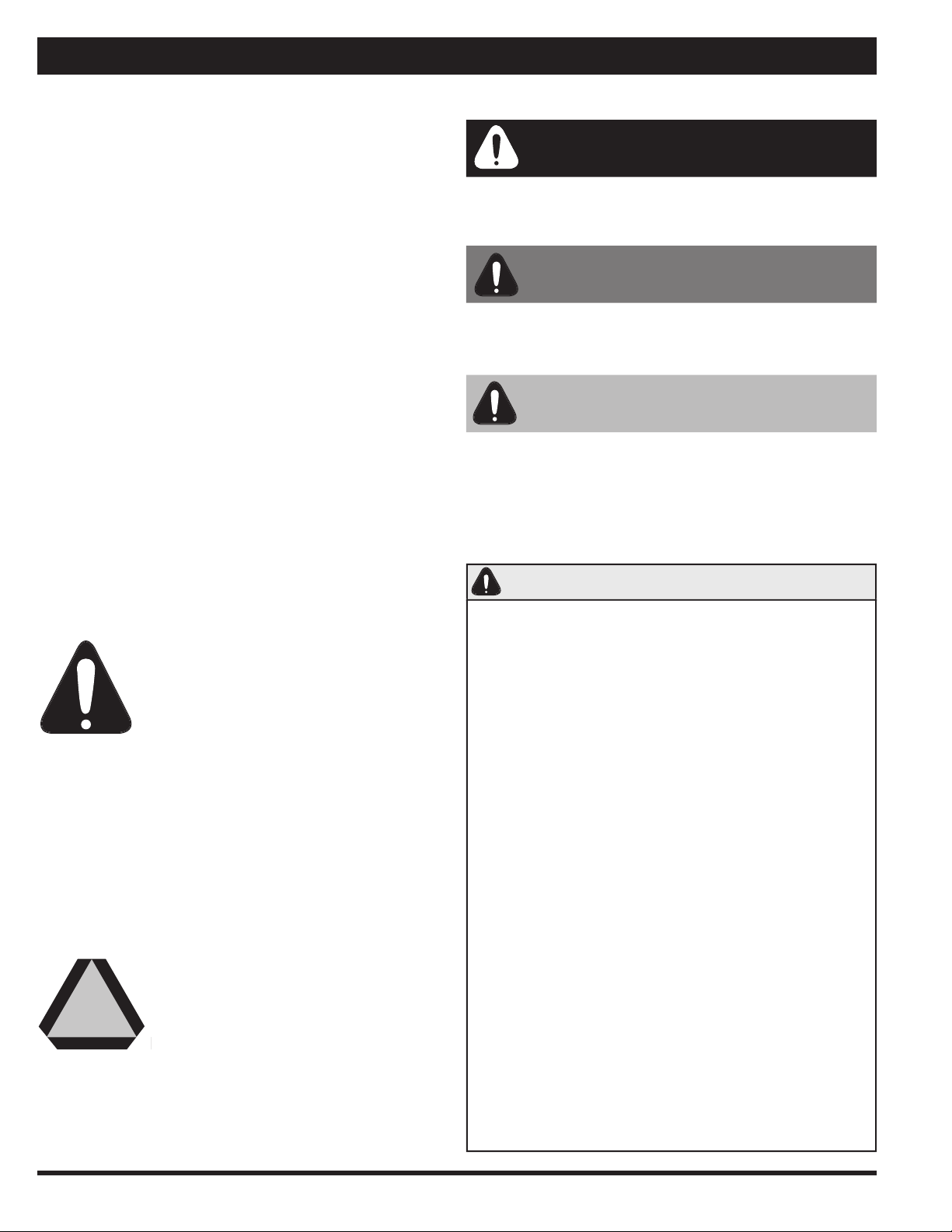
Safety Alert Symbol
The Safety Alert symbol identifi es impor-
tant safety messages in the manual and
on the machine. When you see this sym-
bol, be alert to the possibility of personal
injury or death. Follow all the instructions
in the safety message given. This symbol means atten-
tion, be alert, and your safety is involved.
Three Reasons To Follow Safety Instructions:
1. Accidents disable and kill.
2. Accidents cost.
3. Accidents can be avoided.
Slow Moving Vehicle E
mblem
The Slow Moving Vehicle (SMV) emblem
must be placed on the rear of the ma-
chine and be visible to traffi c approaching
the machine from the rear while traveling
on public roads. Keep the SMV emblem
clean and replace when damaged or emblem materials
have faded. The SMV should only be displayed on the ma-
chine at road speeds less than 40 km/hr (25 MPH).
Safety
▪ The operator is responsible for complying with all
local regulations regarding transporting agricultural
equipment on public roads.
▪ Ensure all lights and refl ectors, as required by local
law, are in place, intact, and clean before transport-
ing machine on public roads.
▪ Connect electrical socket on machine wiring har-
ness to tractor receptacle.
▪ Ensure SMV emblem is clean and properly displayed,
where required by law, before transporting machine
on public roads.
▪ Do NOT allow riders on machine at any time includ-
ing transport of machine on public roads.
▪ Maximum transport speed is 32 km/hr (20 MPH).
Reduce speed on rough roads and surfaces.
▪ Use proper retainer on drawbar hitch pin and attach
safety tow chain to tractor prior to transporting ma-
chine on public roads.
▪ Ensure that transport lock pin is installed and se-
cured in the hole provided for transport.
▪ Tractor light switches should be set for road trans-
port. Refer to tractor operator’s manual for infor-
mation.
Tra
nsport
Safety
DANGER
DANGER:
Indicates an imminently hazardous situation
that, if not avoided, WILL result in death or serious injury
if proper precautions are not taken.
Signal Words
WARNING
:
Indicates a potentially hazardous situation
that, if not avoided, COULD result in death or serious in-
jury if proper precautions are not taken.
CAUTION
:
Indicates a potentially hazardous situation that,
if not avoided, MAY result in minor or moderate injury if
proper practices are not taken, or serves as a reminder to
follow appropriate safety practices.
CAUTION
WARNING
5
Safety
Operating Safety
▪ Ensure that all components in the hydraulic system
are kept in good condition.
▪ Replace any worn, cut, abraded, fl attened, or
crimped hoses and/or metal lines.
▪ Do not attempt any poorly executed repairs to hy-
draulic lines, fi ttings, or hoses by using tape, clamps,
or cements. The hydraulic system operates under
extremely high pressure: 11,033 to 15,859 kPa
(1600 to 2300 PSI). Such repair will fail suddenly
and create unsafe conditions.
▪ Wear proper hand and face protection (e.g. face
shield) when searching for a high pressure hydraulic
leak. Use a piece of wood or cardboard as a back-
drop instead of hands. A high pressure concentrated
stream of hydraulic fl uid can pierce the skin. If such
happens, seek immediate medical attention as in-
fection and toxic reaction could develop.
▪ Before applying hydraulic pressure to the system,
make sure all connections are tight and that lines,
hoses, and couplings are not damaged.
Think Safety,
Work Safely!
▪ REVIEW ALL SAFETY INSTRUCTIONS with all opera-
tors before allowing them to operate the equipment.
Review instructions at least once each year.
▪ All shields and guards must be intact and in po-
sition and securely fastened before operating the
Macerator.
▪ Only use a tractor equipped with ROPS cab and seat
belt. Be careful when operating close to a road or
building, the machine can throw stones and other
objects during operation.
▪ Emphasize the importance of safety when working
around and operating the machine.
▪ Do NOT allow riders on any part of the equipment at
any time.
▪ Always keep hands, feet, and clothing away from
moving parts.
▪ Always lower the Macerator to the ground when
parking.
▪ Use transport lock pin and retainer to secure the
lift linkage of the Macerator before transporting
equipment.
▪ Use safety tow chain at all times.
▪ NEVER attempt to unplug the machine when the trac-
tor is running and hydraulic system is pressurized.
▪ Keep hands, feet, and clothing away from the pickup
area when in operation to avoid entanglement haz-
ards. Do not open or remove shields or guards while
machine is running.
▪ Relieve all pressure from hydraulic lines before dis-
connecting them. Before applying pressure to the
system, make sure all connections are tight and
that hoses and lines have not been damaged.
Hydraulic
Safety
▪ Make sure all hoses and bellows are kept in good
condition and are clean.
▪ Replace any damaged lines or bellows.
▪ Do not exceed 827 kPa (120 PSI) air pressure in
tank and 689 kPa (100 PSI) in air bags.
Air
Safety
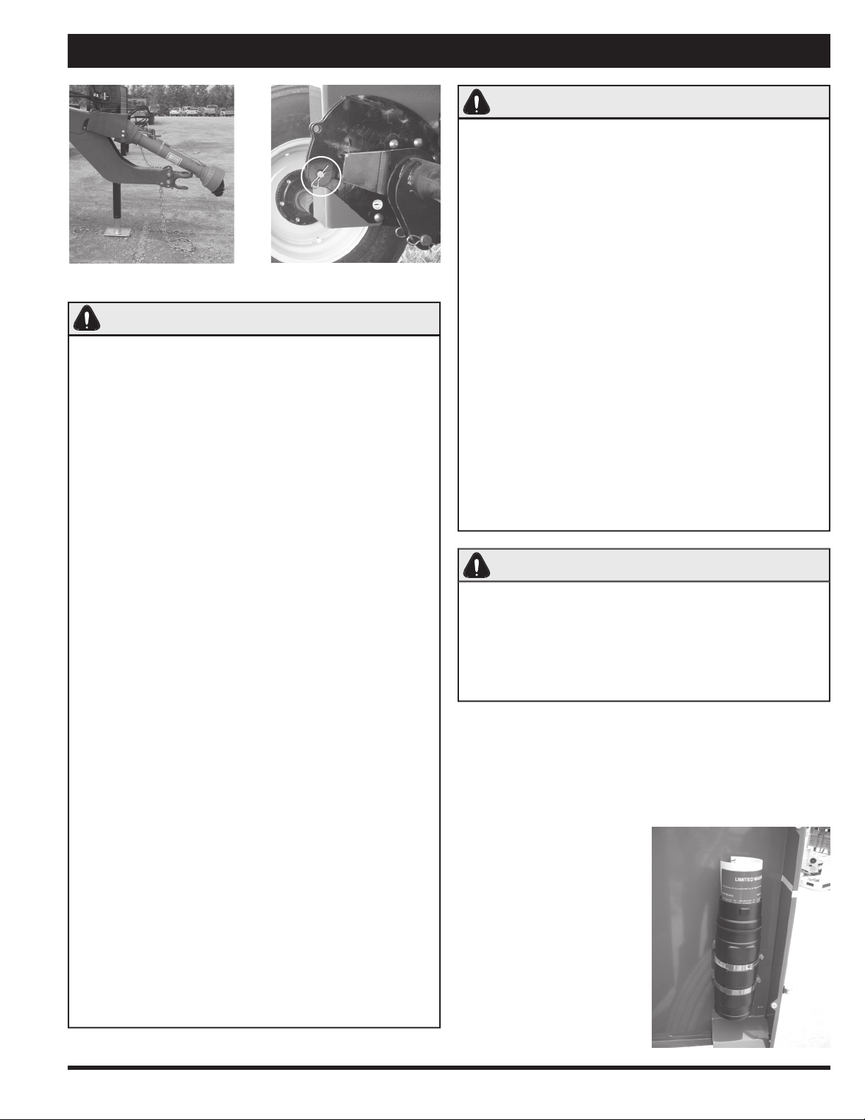
Hitch and safety chain.
Lock travel pin in place.
Keep the Operator’s Manual
in the storage container pro-
vided on the Macerator. The
Operator’s Manual must be
available for use by all op-
erators.
Manual Storage Container
6

Specifi cations
Dimensions
Overall Width 10’6” (315 cm)
Length 11’4” (345 cm)
Height operation 3’6” (105 cm)
transport 5’6” (165 cm)
Weight 3,800 lbs. (1,633 kg)
Tires (4)
Tire Size 11 L - 15 SL
Pressure 138 kPa (20 PSI)
Wheel Hub 6 bolt
Wheel Torque 85 ft. lbs. (115.2 NM)
Pickup
Width 5’6” (165 cm)
Clearance* 14” to 16” (35.5 cm to 40.5 cm)
Tooth Clearance** 10” to 12” (25 cm to 30 cm)
Pickup Tooth Spacing 2.75” (7 cm)
*Under pickup when raised.
**When raised.
Rolls
Width of rubber feed rolls 5’6” (165 cm)
RPM of rubber feed rolls 645 RPM
Min. space between rubber rolls 1/16” (1.6 mm)
Width of steel rolls 5’6” (165 cm)
RPM of top steel roll 1372 RPM
RPM of bottom steel roll 1514 RPM
Min. space between steel rolls 1/32” (.8 mm)
Tractor Requirements
Sug
gested min. tractor size* 80 HP (60 KW)
Suggested min. under frame clearance** 15”
(38 cm)
*Tractor shoul
d be of suffi cient size to maintain operator co
n-
trol in all situations.
**To allow swath to fl ow freely under tractor.
AgLand Macerator
M
odel 6610
Air System
Size of air pressure tank 12 Gallon (46 L)
Max. air pressure in tank 120 PSI
Hydraulic outlets required 1
Operating
Speed
Approximate range* 8 to 16 km/hr (5 to 10 MPH)
*Dep
ending on crop conditions.
Swath Size
Width up to 5’ (150 cm)
Cut Width
Recommended Width 14’ to 16’ (480 cm)
Capacity
Up to 50 ton/hr
Some weights and measurements are approximate.
All specifi cations, statements, and information shown in
this manual are believed to be accurate at the time of print-
ing. Specifi cations are subject to change without notice.
7

Assembly
Attaching Hitch
Sometimes the hitch will be shipped detached from the
unit to allow for a more compact shipping package.
1. Bolt hitch to main frame, Figure 1, using fourteen
5/8” x 1 1/2” carriage bolts. Be sure bolts are se-
curely tightened all around.
2. Remove bearing on front of hitch (C), slide drive
shaft (B) onto override clutch (A) through front bear-
ing hole and reinstall bearing and tighten shaft bolts
on override clutch (A).
3. Install the long hydraulic hose (G) securely with the
3. Install the long hydraulic hose (G) securely with the
clamps (F) provided, as shown in Figure 2.
clamps (F) provided, as shown in Figure 2.
A. Override Clutch
B. Drive Shaft
C. Front Hitch Bearing
D. A Frame Cover (Back)
E. A Frame Cover (Front)
F. Hose Clamp
G. Long Hydraulic Hose
Figure 1
Figure 2
B
C
D
E
A
F
G
8
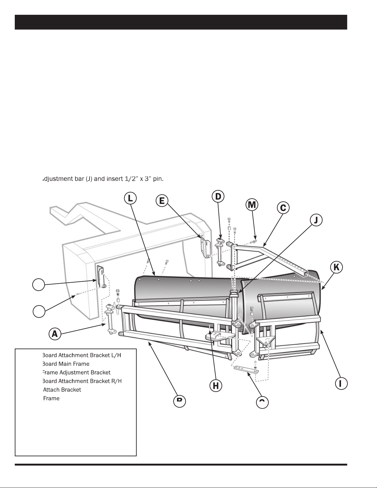
A. Mold Board Attachment Bracket L/H
A. Mold Board Attachment Bracket L/H
B. Mold Board Main Frame
B. Mold Board Main Frame
C. Main Frame Adjustment Bracket
C. Main Frame Adjustment Bracket
D. Mold Board Attachment Bracket R/H
D. Mold Board Attachment Bracket R/H
E. Quick Attach Bracket
E. Quick Attach Bracket
F. Small Frame
F. Small Frame
G. Extension Adjustment Bar
H. Adjustment Pin
J. Adjustment Bar
K. Short Mold Board Sheet
L. Long Mold Board Sheet
M. Lynch Pin
Assembly (Attachments)
1. Attach mold board attachment bracket L/H (A) to the
mold board main frame (B) and attach main frame
to quick attach bracket (E - already installed) and in-
sert lynch pin.
2. Attach mold board attachment bracket R/H (D) to
the adjustment bar (C) and attach bar to bracket (E
- already installed) and insert lynch pin (M).
3. Attach small frame (F) to the main frame (B), using
1/2” x 1 1/2” hex bolts with bushing, washer, lock
washer, and hex nut.
4. Attach extension adjustment bar (G) to frame (F)
using 1/2” x 1 1/2” std bolt, bushing, washer, lock
washer and std nut and insert adjuster pin (H).
5. Slide main frame adjustment bracket (C) through
the adjustment bar (J) and insert 1/2” x 3” pin.
the adjustment bar (J) and insert 1/2” x 3” pin.
Mold
B
oard Sheet Installation
6. Install short mold board (K) to outside portion of
main frame (F) using 5/16” x 3/4” carriage bolts
and hex nuts.
7. Install longer mold board sheet (L) on to the main
frame (B) using 5/16” x 3/4” carriage bolts, overlap-
ping the short mold board sheet.
8. All bolts holding the mold board sheets can now be
fully tightened.
9. Adjust angle of mold board by moving adjustment
bracket (C) in or out of adjustment bar (J) to pre-
ferred mold board angle and insert 1/2” x 3” pin.
The tighter angle will result in less inversion. The
wider angle will give you a greater inversion.
Swath Inverter (Mold Board)
A
F
F
E
D
C
B
B
G
G
H
K
L
J
E
M
Mold Board Attachment
M
9
A
B
C
D
E
E
A
G
H
F
Assembly (Attachments)
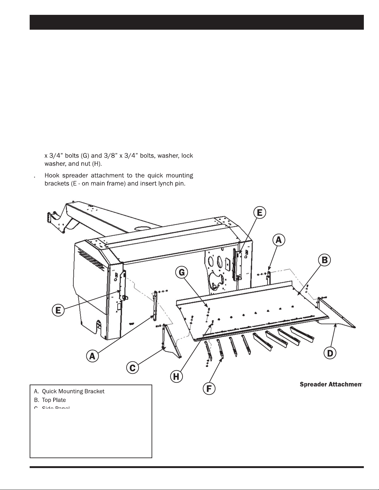
Spreader Attachment
The spreader attachment allows the Macerator to spread
a wider swath and leave a thinner layer on the fi eld for
greater sun and wind exposure.
The spreader attachment quick attaches onto the rear of
the main frame.
1. Attach bracket (A) to the side panels (C and D) using
3/8” x 1 1/4” bolts with washer, lock washer, and
nut.
2. Mount side panels (C and D) to top plate (B) with
5/16” x 3/4” bolts, washer, and lock washer.
3. Mount defl ector fi ns (F) to top plate (B) using 3/8”
x 3/4” bolts (G) and 3/8” x 3/4” bolts, washer, lock
x 3/4” bolts (G) and 3/8” x 3/4” bolts, washer, lock
washer, and nut (H).
4. Hook spreader attachment to the quick mounting
4. Hook spreader attachment to the quick mounting
brackets (E - on main frame) and insert lynch pin.
Spreader Attachment
Spreader Attachment
A. Quick Mounting Bracket
B. Top Plate
C. Side Panel
C. Side Panel
D. Side Panel
E. Quick Mounting Bracket (on main frame)
F. Defl ector Fin
G. Bolt
H. Bolt
10
Assembly (Attachments)
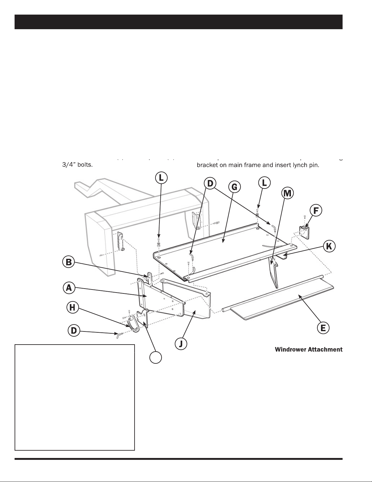
Windrower Attachment
The windrower attachment allows you to direct the cut hay
down to keep a tighter windrow, or out for a wider swath
width.
1. Insert 3/8” x 1 1/4” bolts through side panel (A) and
attach quick mounting bracket (B).
2. Mount side panels (A and K) to top plate (G) with
5/16” x 3/4” bolts. Do not tighten bolts.
3. Mount side bracket (C) to panel (A) with 3/8” x 3/4”
bolts. Only two bolts.
4. Insert windrow baffl e (E) into hole of side bracket
(C).
5. Mount the other side bracket (F) to side panel (K)
5. Mount the other side bracket (F) to side panel (K)
with 3/8” x 3/4” bolts.
with 3/8” x 3/4” bolts.
6. Mount adjustment bracket (H) using 5/16” x 1 1/2”
socket head cap screw and wing bolt (D).
7. Install left and right side width adjusters (J and M)
using 3/8” x 1” bolt and bushing (L) through top
plate (G).
8. Insert wing bolt with washer (D) through slot into
width adjusters (J and M).
9. Tighten all bolts evenly.
10. Hook spreader attachment to the quick mounting
10. Hook spreader attachment to the quick mounting
bracket on main frame and insert lynch pin.
A. Side Panel
B. Quick Mounting Bracket
C. Left Side Bracket
D. Wing Bolt
E. Windrow Baffl e
F. Right Side Bracket
G. Top Plate
H. Adjustment Bracket
J. Width Adjuster
K. Side Panel
L. Bushing
M. Width Adjuster
Note:
Use supplied washers and nuts with described bolts
above.
Windrower Attachment
A
B
C
D
E
F
G
H
K
M
D
L
J
L
11
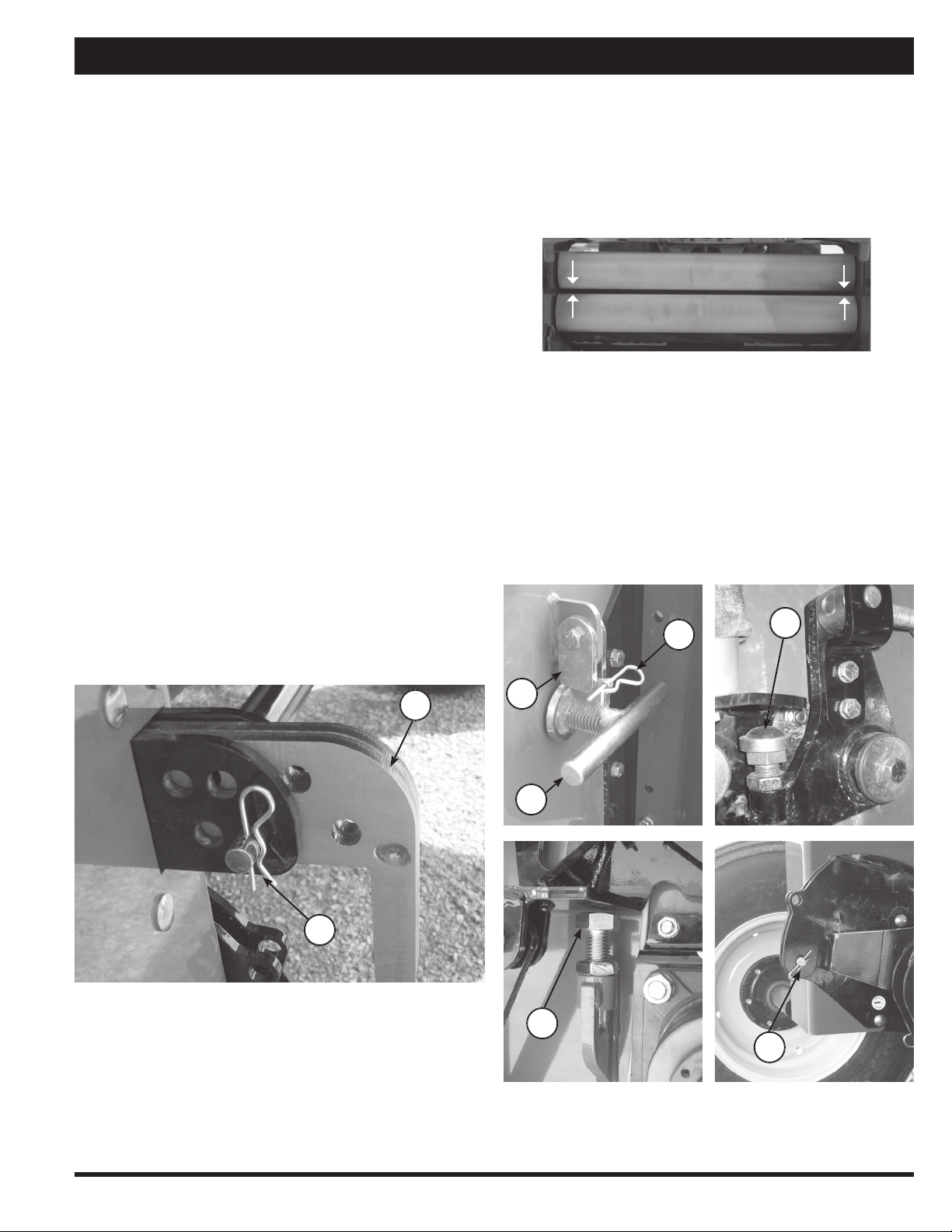
1. Raise the Macerator using the hydraulics.
2. Turn crank (A) clockwise to widen the gap or counter-
clockwise to narrow the gap. 1 turn = .04” (1 mm).
For a better fi ne tune, adjust bolt (D).
3. Be sure to set the gap exactly the same on both
sides, use gauge.
4. Put crank lock (B) in place and secure with pin (C).
5. To assure that the rolls do not touch, the safety stop
is set by the factory at 1/32” or .8 mm.
6. If safety stop (E) needs adjusting put travel pin (F) in
place while unit is raised.
7. Adjust the safety stop bolt (E) as needed. Be sure the
rolls don’t touch during operation.
8. Repeat steps 1–7 to fi ne tune if necessary.
Field Setup
A
Use with a tractor having a minimum of 80 HP (60 KW).
Tractor should have suffi cient ground clearance for
swath to pass cleanly under it.
PTO Speed
Unless otherwise specifi ed, units are shipped with 1000
PTO speed. Units with 540 RPM PTO are also available,
contact dealer.
The PTO should be run at approximately 1000 RPM. The
front rubber rolls run at 645 RPM and the bottom steel
roll runs at 1514 RPM at a tractor PTO speed of 1000.
The upper steel roll runs at 1372 RPM at 1000 tractor
PTO speed.
Pickup
Height & Adjustment
The Macerator 6610 pickup should be adjusted so that
it will cleanly pick up all material off of the fi eld without
gouging the soil. You may have to reset the height a few
times to arrive at the best working height.
1. If your pickup is too low to the ground use your trac-
tor hydraulic cylinder control to raise the pickup.
2. Remove pin (A) and slide adjuster bar (B) to desired
height. Pushing bar in raises machine and pulling
the bar out lowers the machine.
3. Reinsert pin and lock in place.
Gap Gap
B
A
Steel Roll Adjustment
For best results adjust the Macerator 6610 for your specif-
ic fi eld conditions. The smaller the gap between the steel
serrated rolls the more aggressive will be the maceration
of the hay. Both the space between the rolls and the air
pressure need to be adjusted for maximum effi ciency.
B
C
E
F
D
12

Field Setup
Preparation (Air System)
The purpose of the air system on the Mac-
erator 6610 is to keep continuous pres-
sure on the rolls.
The pressure can make a difference on
how well the machine performs on the
fi eld. While the pressure on the rubber rolls may not be
as crucial, too much pressure on the steel rolls will result
in considerable leaf loss and some plugging may result in
short wet hay.
Before heading out to t
he fi eld, make sure the air pres-
sure tank has a minimum of 100 PS
I pressure
. This sho
uld
give the operator suffi cient
air supply for the day.
Rubber Roll Pressure Adjustment
The rubber rolls are designed to take the
material from the pickup and feed it into
the steel rolls. The rubber rolls do not crush
or crimp the hay.
As a standard setting, we recommend 20–
30 PSI pressure on the rubber rolls. Regulate the pressure
by pulling out the knob on the regulator marked ‘rubber
rolls’ and turning it clockwise or counter-clockwise. When
turning the knob counter-clockwise you should hear the
air escaping from the regulator.
In extreme conditions, increase or decrease the pressure.
For example, very heavy swaths may require more pres-
sure.
Steel Roll Pressure Adjustment
The steel serrated rolls (rear) take the ma-
terial from the rubber rolls and crack the
stems. To achieve the right setting, some
fi eld testing may be necessary.
1. Pull out the knob on the air regulator
marked ‘steel rolls’ and turn the knob clockwise or
counter-clockwise to set the pressure to the steel
rolls at approximately 5-35 PSI in alfalfa, 40–80 in
grasses
2. If you experience too much leaf loss or the plants are
crushed too intensely, lower the air pressure.
3. If there is not enough maceration, increase pressure
to the rolls by increasing the air pressure. Make sure
the gap is adjusted (see page 12).
Field Notes:
____________________________________________
____________________________________________
____________________________________________
____________________________________________
____________________________________________
____________________________________________
____________________________________________
____________________________________________
____________________________________________
____________________________________________
____________________________________________
____________________________________________
____________________________________________
____________________________________________
____________________________________________
____________________________________________
____________________________________________
____________________________________________
____________________________________________
____________________________________________
____________________________________________
____________________________________________
____________________________________________
____________________________________________
____________________________________________
____________________________________________
____________________________________________
____________________________________________
____________________________________________
____________________________________________
____________________________________________
____________________________________________
____________________________________________
13

Maintenance
Use Good Safety Practices When
Working On This Machine
Before doing any maintenance or service on the ma-
chine you must:
□
Park machine on a solid level surface.
□
Lower the machine fully to the ground or onto
blocks.
□
Disengage all power.
□
Put the tractor transmission in PARK or apply the
tractor parking brake.
□
Stop the tractor engine and remove key from the
ignition.
□
Look and listen. Make sure all moving parts have
stopped.
First Time Use
□
Tighten hub bolts A–E* after the fi rst 1 hour of oper-
ation and repeat procedure after 10 hours and 50
hours.
*
Importa
nt
Hubs A - tighten to 60 ft. lbs.
Hubs B - tighten to 30 ft. lbs.
Hubs C - tighten to 9 ft. lbs.
Hubs D - tighten to 6 ft. lbs.
Hub E - tighten to 15 ft. lbs.
Daily
□
Check and tighten all hub bolts.
□
Remove all dirt and crop deposits from machine.
After The First 25 Hours Of Use
□
Check bearing and set screw tightness.
At The Beginning Of Each Season
□
Review all safety instructions.
□
Carefully inspect all components for excessive wear
or hazardous con-
ditions.
□
Lubricate the ma-
chine at all lubrica-
tion points.*
□
Check tires for cor-
rect infl ation pres-
sure.
□
Tighten bolts.
*See lubrication sched-
ule and procedures on
page 1
7.
Checklist
A
B
C
E
C
A
B
CAUTION
D
D
14
Maintenance
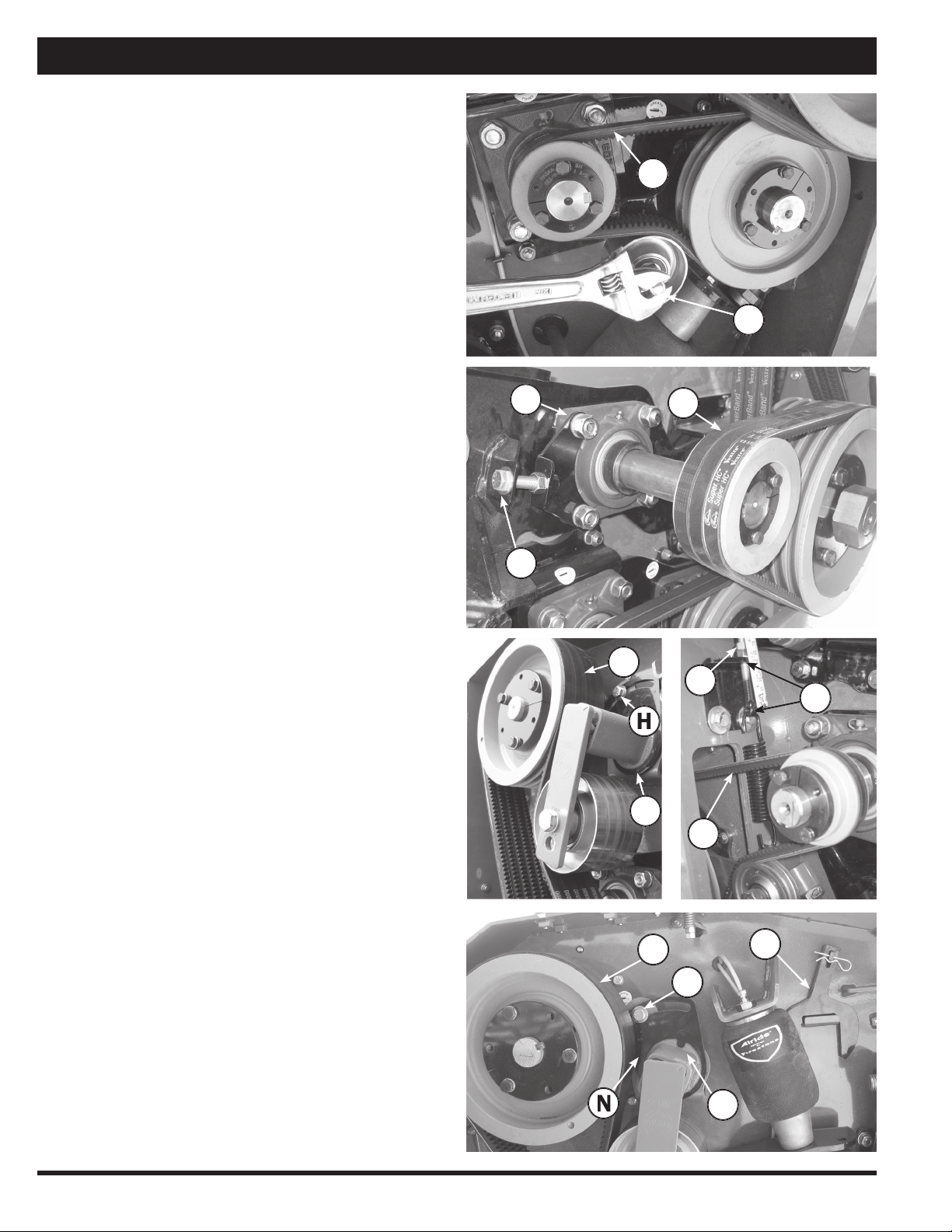
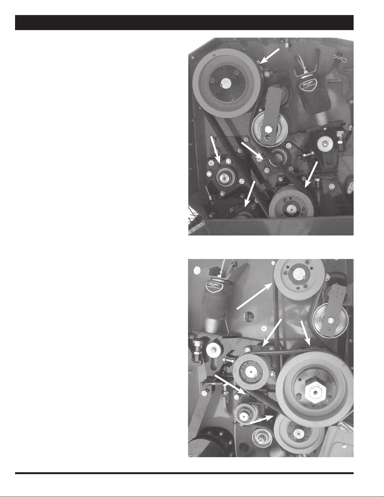
Roll Drive Belt Replacement
Replace worn or damaged belts as follows:
1. Raise Macerator and secure travel safety pin, see
page 6.
2. To remove belts (A) loosen and turn fl attened bolt (B)
counter-clockwise.
3. To remove belts (C) loosen 4 bolts (D) then loosen
bolt (E) and slide roll forward.*
4. To remove belt (F) loosen bolt (G) behind tightener,
then loosen bolt (H) and slide tightener forward.
5. To remove belt (M) loosen bolt (N) on the other side
of the panel behind tightener. Take tightening wrench
(O) (use a pipe for leverage) and hold spring loaded
tightener (P) fi rmly in place while loosening bolt (Q),
then release tension slowly with wrench.
6. Replace all belts and tighten bolts (reverse sequence
of steps 2–5).
7. To remove belt (J) loosen spring tension by turning
off nut (K) counter-clockwise. To tighten the belt,
tighten nuts (K) until you measure approximately 2
inches (L) or proper tension on the belt.
8. Reinstall all covers.
* To maintain proper roll alignment be sure to adjust the
oppo
site tightener on the other side of the machine.
M
N
Q
P
O
E
D
C
B
A
F
H
G
L
K
J
15
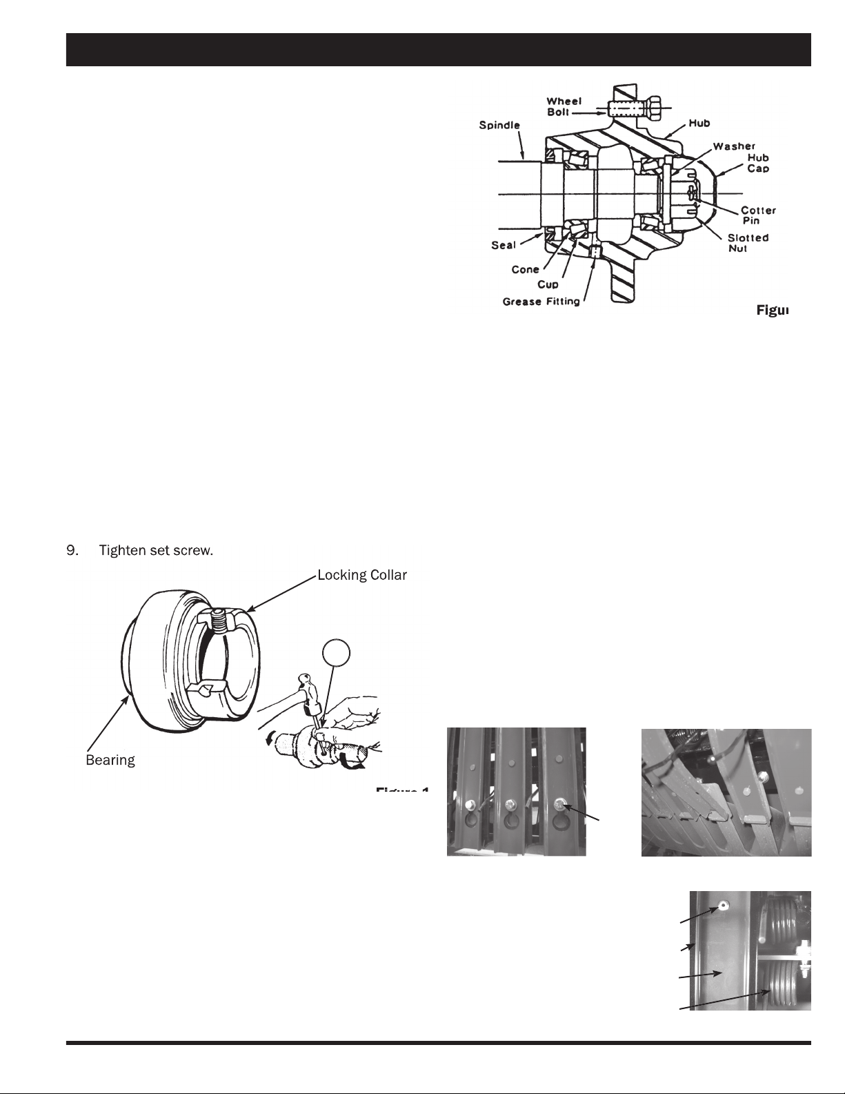
Figure 1
Figure 1
A
Locking Collar
Bearing
Maintenance
Bearing Replacement
Sealed ball bearings are held in position on the shaft by
a locking collar, Figure 1, which is rotated to lock the as-
sembly on the shaft and secured by a set screw. To re-
move bearing:
1. Loosen set screw.
2. Use a drift punch inserted in the drift pin hole to
rotate and loosen the locking collar (A). Rotate the
locking collar counter-shaft rotation
3. Remove the locking collar.
4. Support the shaft, for easier assembly later.
5. Remove the bolts for the bearing fl anges.
6. Slide the bearing and the fl anges from the shaft.
Note: Cleaning paint and corrosion from the shaft
will make removal easier.
7. Put on the new bearing and fl anges.
8. Replace locking collar on the shaft. Rotate the lock-
ing collar in the direction of the shaft rotation until
lightly engaged. Tighten the collar by hitting it with a
drift pin punch inserted in the drift pin hole rotating
it further until fully tightened
9. Tighten set screw.
9. Tighten set screw.
Figure 2
Figure 2
Replacing or Repacking Wheel Bearings
1. Remove wheel hubs and disassemble.
2. Clean bearings, seals, caps, washers, nuts, and hubs
with kerosene or other solvent.
3. Replace bearings or seals if worn or damaged.
4. Pack bearing cones and seals with No. 2 multipur-
pose lithium grease or equivalent.
5. Reassemble hub and bearings, Figure 2.
6. Press cups against the shoulder in the hub.
7. Press seal fl ush into hub after bearing.
8. Place hub on shaft taking care not to damage the
seal.
9. Tighten the wheel bearing nut. Do not overtighten.
10. Secure nut with a cotter pin.
11. Be sure to replace hub cap.
Pickup Teeth, Wrappers, and Wear Strips
Check for bent, broken or loose parts. If it is necessary to
replace teeth or related parts, proceed as follows.
1. Ensure that your Macerator is blocked securely.
Loosen the bolt holding the wrapper(s) on pickup,
Figure 3. Lift the wrapper on top and slide forward to
remove.
2. Should the plastic wear strip require removal and
replacement, drill out or carefully grind off the ‘pop’
rivets. Replace strip with new rivets, Figure 5.
3. Install new teeth or wrapper(s).
Figure 3
‘Pop’ Rivets
Figure 5
Plastic Wear Strips
Wrapper
Teeth
Figure 4
Bolt
16
Lubrication
General Information
A NLGI No. 2 multi-purpose high temperature lithium base
grease is recommended.
Use a manual grease gun for all greasing. Air powered
grease guns may damage the seal on the bearings.
Wipe all grease fi ttings with a clean cloth before greasing
to avoid injecting dirt or grit in the bearings.
At The Beginning Of The Season
Grease all the sealed bearings, front rolls (two places),
rear rolls (two places) and drive shaft (one place), Figures
1 and 2.
Figure 1
Figure 2
17

Trouble Shooting
Problem Possible Cause Solution
Pickup is skipping swath or not
picking cleanly.
▪ Missing or broken pickup teeth.
▪ Pickup too high.
▪ Driving too fast for pickup speed.
▪ Not following the same direction as
swath was cut.
▪ Replace missing teeth.
▪ Adjust pickup height.
▪ Use lower tractor gear with higher
RPM.
▪ Follow same direction as swath cut.
Material wrapping in pickup.
▪ Nylon wear plates are missing or
worn.
▪ Pickup and travel speeds are not
matched.
▪ Replace missing or worn nylon
plates.
▪ Match pickup and ground speed as
close as possible.
Breakage or bending of pickup teeth.
▪ Running pickup too low.
▪ Excessive pickup rotation speed in
rough or rocky conditions.
▪ Adjust pickup height.
▪ Reduce pickup or ground speed.
Excessive noise or heat from gear
box.
▪ Insuffi cient oil in gear box.
▪ Worn or broken parts inside gear
box.
▪ Top up gear oil as needed.
▪ Replace parts as needed.
Air pressure does not hold in air tank
and air bags.
▪ Broken air line.
▪ Torn or punctured air bag.
▪ Air regulator not working.
▪ Repair or replace line as needed.
▪ Replace air bag as needed.
▪ Clean or replace regulator.
Pickup does not rise or lower.
▪ Worn or punctured hydraulic cylin-
der or hydraulic oil line.
▪ Bushings too tight.
▪ Replace hydraulic lines and cylin-
ders as needed.
▪ Replace or clean bushings.
Pickup height adjustment does not
hold.
▪ Broken or worn parts on adjuster.
▪ Replace worn parts as needed.
Rubber rolls not feeding properly.
▪ Air pressure too high or low.
▪ Gap between rolls too tight or too
wide.
▪ Adjust air pressure using regulator.
▪ Adjust gap width.
Wax build up on steel rolls.
▪ Temperature and hay conditions
cause the wax to come off of the
plant and stick to the rolls.
▪ The wax will come off after the rolls
cool down. A thin layer of wax/
leaves will build up on the rolls.
Excessive leaf loss.
▪ Too much air pressure on steel
rolls.
▪ Hay conditions too dry.
▪ The gap between steel rolls is too
narrow or the rolls are going too
fast.
▪ Release air pressure.
▪ Condition hay early in the morning.
▪ Adjust gap between steel rolls.
Hay is not being macerated.
▪ Not enough air pressure on steel
rolls.
▪ Gap between rolls is too wide.
▪ Windrow is too thick.
▪ Steel rolls not running fast enough.
▪ Adjust air pressure as required.
▪ Narrow the gap between steel rolls.
▪ Cut wider or thinner windrows.
▪ Increase tractor RPM.
Swath not being inverted completely.
▪ Mold board is not adjusted properly.
▪ Adjust mold board angle. The
tighter angle will result in less inver-
sion. The wider angle will result in a
greater inversion.
18

LIMITED WARRANTY
Warranty service will be performed by AgLand Dealer authorized to sell the Macerator.
AGLAND WARRANTY
AgLand Industries Inc. manufactures the AgLand
Macerator. AgLand Industries Inc. (Manufacturer)
warrants each Macerator sold by it to be free of de-
fects in material or workmanship under normal use
and service. The sole obligation of the Manufacturer
is limited to repairing or replacing, as the Manufac-
turer may elect, any part or parts that prove, in the
Manufacturer’s judgement, to be defective in mate-
rial or workmanship within one year* after delivery
to the original Retail Purchaser under normal farm
use. The defective part or parts will be replaced or
repaired only to the original Retail Purchaser. War-
ranty repair or replacement will be done at the loca-
tion of the AgLand dealer who sold the Macerator.
Defective parts must be returned to the Manufactur-
er or Dealer who sold the Macerator at the expense
of the Retail Purchaser to be inspected by the Manu-
facturer. Purchaser must give written notice to the
Dealer from whom the Macerator was purchased of
any claimed defect and the Dealer will repair or re-
place the part or parts found to be defective.
*3 months after delivery when purchased by a com-
mercial operator.
Note: The sole remedy of the Purchaser for claim
under this warranty is the repair or replacement of
defective parts.
This warranty does not extend to the drive compo-
nents or tires, which are made by other manufactur-
ers and carry warranties from said manufacturers.
There are no representations, warranties, or condi-
tions, express or implied, statutory or otherwise, ex-
cept those herein contained and no agreement col-
lateral otherwise except those herein contained, and
no agreement collateral hereto shall be binding upon
either party unless in writing hereon or attached
hereto, signed by the Purchaser and accepted by the
Manufacturer at its head offi ce.
SERVICE AND WARRANTY
INFORMATION
The Manufacturer’s liability under this warranty is
limited to the repairing or replacing of parts only, and
the Manufacturer shall in no event be liable to the
Retail Purchaser for consequential damage or loss
of profi ts sustained by it as a result of any defect in
material or workmanship on any of the equipment
covered by this warranty.
The Macerator is warranted for agricultural use only.
This warranty does not cover claims resulting from
any use for other than agricultural applications.
Altering, modifying or adding additional equipment
which is not approved for installation on the Macera-
tor by the Manufacturer will void this warranty.
All warranties are subject to legislation of the state
or province in which the Macerator is sold.
Note: There are no warranties, express or implied,
by the Manufacturer or its Dealer regarding the
Macerator except the warranty against defects in
the material or workmanship expressed herein. No
person is authorized to bind the Manufacturer to
any other warranty whatsoever.
The Manufacturer reserves the right at any time
to make changes in the design, material, parts, or
specifi cations of the Macerator without thereby be-
coming liable to make similar changes in equipment,
machinery or parts previously manufactured.
AgLand Industries Inc.
Issue Date July 2004 Part No. 808321
Cost $14.00 plus $2.50 postage and handling (prices CDN)
Printed in Canada JZ 0305
Table of contents
Other AgLand Farm Equipment manuals


Popular Farm Equipment manuals by other brands

Schaffert
Schaffert Rebounder Mounting instructions

Stocks AG
Stocks AG Fan Jet Pro Plus 65 Original Operating Manual and parts list

Cumberland
Cumberland Integra Feed-Link Installation and operation manual

BROWN
BROWN BDHP-1250 Owner's/operator's manual

Molon
Molon BCS operating instructions

Vaderstad
Vaderstad Rapid Series instructions


