3
AGORAMODELS SHELBY SUPER SNAKE
STEP 1
STEP 2
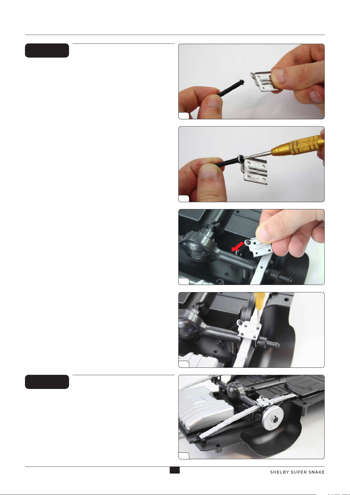
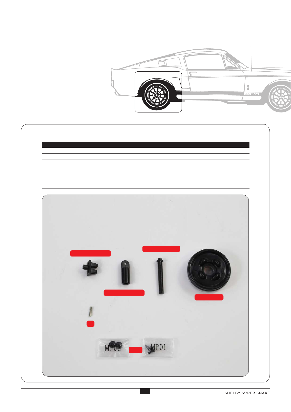
JOIN THE SHOCK ABSORBER CYLINDER TO
THE SHOCK ABSORBER SUPPORT
Align the shock absorber cylinder with the shock absorber
support and position the parts together so that the three
holes are aligned. Push the pin through the aligned holes,
leaving the grooved end protruding as shown. Fully insert
the pin by squeezing the ends with a pair of pliers.
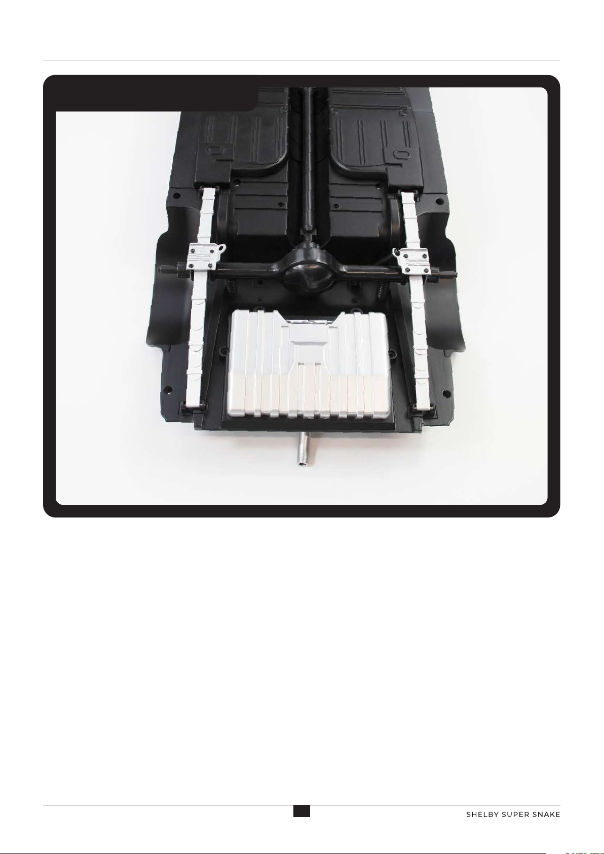
FIX THE SHOCK ABSORBER SUPPORT
TO THE CHASSIS
Take the chassis assembly and unscrew the spring
plate mounted in Stage 20. Put the plate and
screws carefully to one side for use in the next step.
Fit the lug on the shock absorber support into
the hole in the chassis, ensuring that the shock
absorber cylinder orients in the direction shown in
picture 2. Holding the part in place, turn the chassis
over and screw in place using a TYPE MP01 screw.
1
1
2
2
3
3 4
ADVICE FROM THE EXPERTS
The shock absorber support only goes
one way. If it doesn't sit flush, rotate it 180
degrees and try again.
!
Stage 56: Shock Absorber and Left Rear Brake