Agora Shelby GT500 Super Snake Manual

1
AGORAMODELS SHELBY SUPER SNAKE
STAGE 31: STABILIZER BAR AND
LOWER SUSPENSION ARMS
STAGE 32: UPPER SUSPENSION ARMS
STAGE 33: FRONT INTERIOR
FLOOR AND GEAR LEVER
STAGE 34: FRONT SIDE WALLS,
PEDALS AND SWITCHES
STAGE 35: DASHBOARD AND FUSE COVER
STAGE 36: DASHBOARD TRIM,
DIALS AND SHELBY BADGE
STAGE 37: CENTRAL DIALS, CAR RADIO
AND GLOVE COMPARTMENT
STAGE 38: REAR FLOOR AND
FRONT SEAT BELTS
Pack 05 |Build Instructions
Your Shelby GT500 Super Snake is a finely detailed model replicating every aspect
of the original car. From the paint color to the smallest interior details, every piece is
precisely reproduced. .
In your fifth model pack, you will assemble:

2
AGORAMODELS SHELBY SUPER SNAKE
Stage 31: Stabilizer Bar and Lower Suspension Arms
In stage 31, you will continue to
build the suspension system.
Name Quantity
Stabilizer Bar and Lower Suspension Arms 1
Pins 2
Screws TYPE MP03 3 [inc. 1 spare]
Screws TYPE MD02 3 [inc. 1 spare]
STAGE 31 PARTS LIST
Stabilizer Bar and Lower Suspension Arms
Pins ScrewsScrews

3
AGORAMODELS SHELBY SUPER SNAKE
STEP 1
ATTACH THE STABILIZER BAR AND LOWER
SUSPENSION ARMS TO THE CHASSIS
ASSEMBLY.
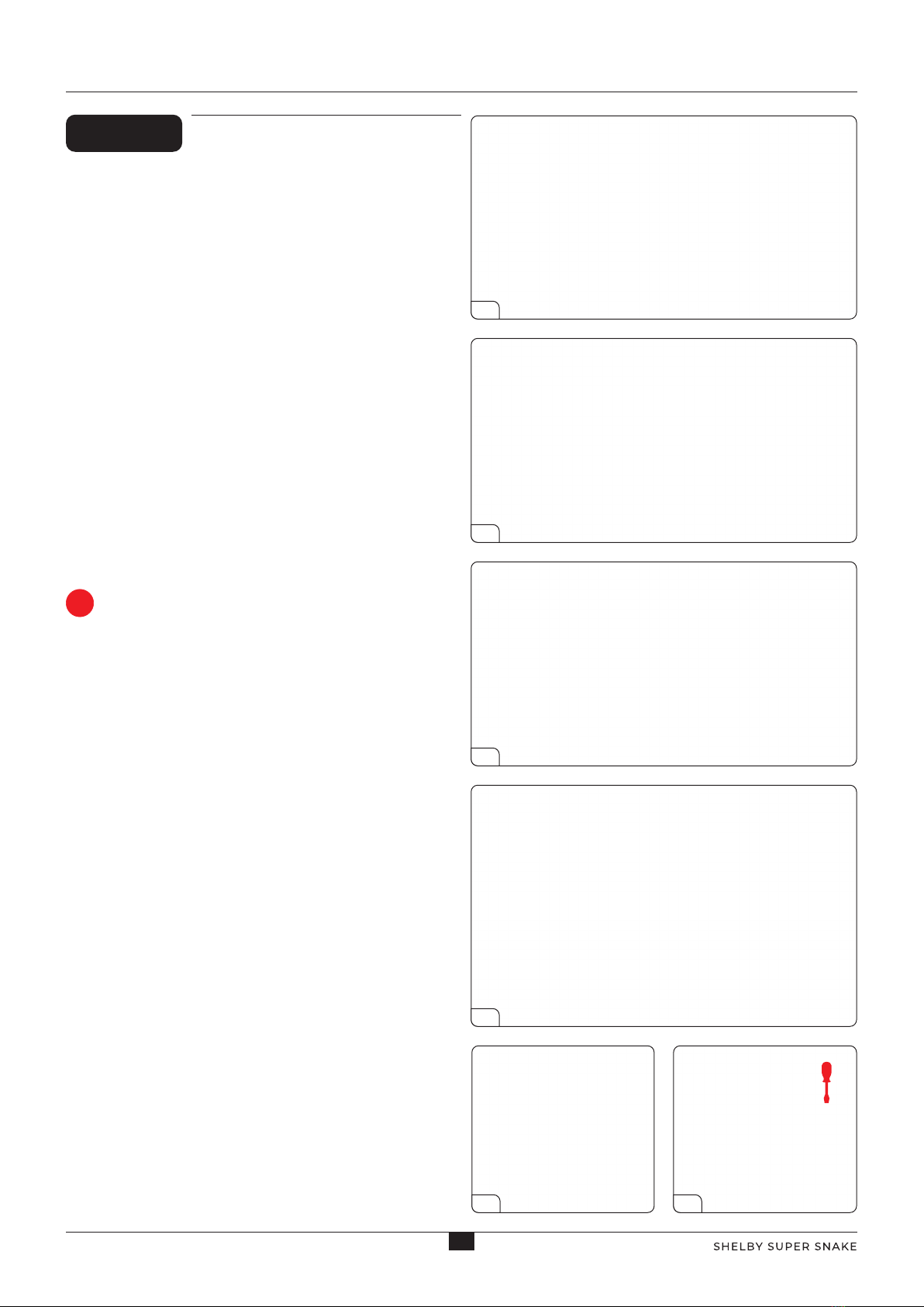
Take the Chassis Assembly and place it upside down on your
worktable. Place the Stabilizer Bar in front of the frame as
shown. Check you have it the right way up – the flat surface
of the Stabilizer Bar faces down. This Bar is equipped with a
Lower Suspension Arm for each front wheel. Now position
the Lower Suspension Arm in the Arm Mounts fitted in Stage
30. Align the holes in the Arms and the Mounts. Insert one
of the pins into the hole as shown in picture 3. Ensure that
the ridged end of the pin protrudes from the hole. Squeeze
the pin into the hole using a pair of pliers as shown in picture
4, checking to see that the pin reaches the other side of the
Mount. Take extra care not to damage the paint work.
Repeat on the Lower Suspension Arm on the opposite side.
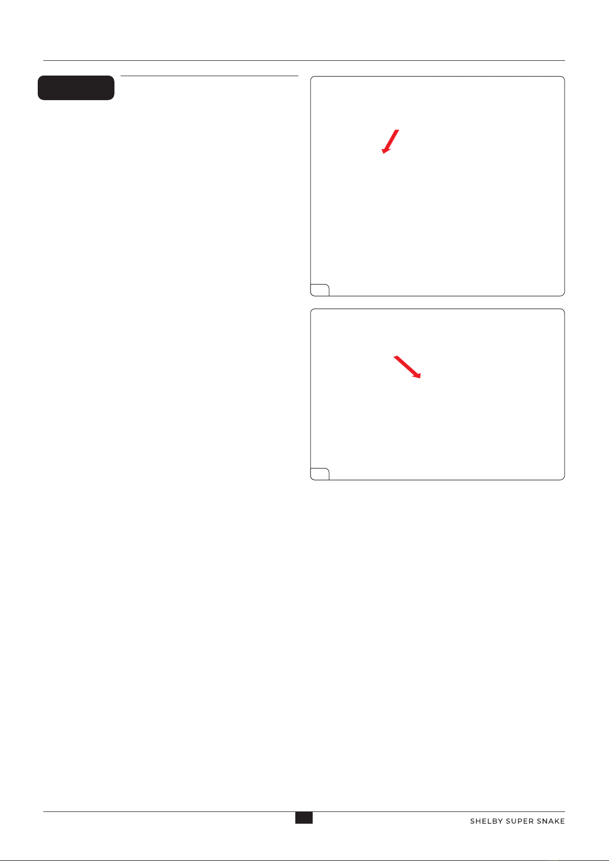
Insert the Strut Rods into the corresponding holes in the
chassis. Holding the Strut Rods in one hand, turn the Chassis
Assembly over and fix into place using 2 x TYPE MP03 screws.
Do not overtighten. The Strut Rods will be loose in the chassis
to allow the front suspension to move.
1
2
3
4
Stage 31: Stabilizer Bar and Lower Suspension Arms
5 6
ADVICE FROM THE EXPERTS
Cover your pliers in masking tape to help
prevent damage to your paintwork.
!

4
AGORAMODELS SHELBY SUPER SNAKE
STEP 2
FIT THE TIE-ROD ASSEMBLY TO THE CHASSIS
Turn the Chassis Assembly over again and position the
Tie-Rod Assembly completed in Stage 30, onto the chassis
as shown. Note that the Pitman Arm must be fitted on the
Steering Gear. Also note the Left Tie Rod must be fitted
under the Steering Gear mounted on the chassis beam
(indicated in picture 2). Keep screws MD02 safely as they
will be used later.
1
2
Stage 31: Stabilizer Bar and Lower Suspension Arms

5
AGORAMODELS SHELBY SUPER SNAKE
Stage 31: Stabilizer Bar and Lower Suspension Arms
Stage 31 complete!

6
AGORAMODELS SHELBY SUPER SNAKE
Stage 32: Attaching the Upper Suspension Arms
Construct the Upper
Suspension Arms and attach
them to the chassis.
Name Quantity
Upper Suspension Arms 2
Suspension Arm Supports 2
Pins 2
Screws TYPE MD06 5 [inc. 1 spare]
Screws TYPE MD02 3 [inc. 1 spare]
STAGE 32 PARTS LIST
Upper Suspension Arms
Pins
Suspension Arm Supports
Screws

7
AGORAMODELS SHELBY SUPER SNAKE
STEP 1
CONSTRUCT THE UPPER SUSPENSION ARMS
Take one of the Upper Suspension Arms and one of the
Suspension Arm Supports. Ensure you have the parts
the correct way up by checking the picture. Push the
two parts together so that the holes align. Push a Pin
through the holes, ensuring that you leave the ridged end
protruding. Push the Pin through so that it is flush with
the Upper Suspension Arms using a pair of pliers. Repeat
this process using the remaining parts.
1
2
3
4
Stage 32: Attaching the Upper Suspension Arms

8
AGORAMODELS SHELBY SUPER SNAKE
STEP 2
FIX THE UPPER SUSPENSION ARMS TO
THE CHASSIS
Take the Chassis Assembly and position the Upper
Suspension Arms created in STEP 1 on the side of the
chassis as shown. Check the Suspension Arm can
move freely to 90 degree position. Fix in place using
2 x TYPE MD06 screws. Repeat this process on the
opposite side of the chassis.
1
2
Stage 32: Attaching the Upper Suspension Arms
Stage 32 complete!

9
AGORAMODELS SHELBY SUPER SNAKE
Stage 33: Attaching the Gear Lever to the Front
Interior Floor
You are now going to start
building the front interior of the
Shelby Super Snake.
Name Quantity
Front Interior Floor 1
Gear Lever 1
Screws TYPE MP01 2 [inc. 1 spare]
STAGE 33 PARTS LIST
Front Interior Floor
Screws
Gear Lever

10
AGORAMODELS SHELBY SUPER SNAKE
STEP 1
FIXING THE GEAR LEVER
Position the interior floor on your workbench as shown.
Take the Gear Lever and align the lug on the base with
the hole in the Floor. Ensure the Gear Lever knob is facing
the direction shown. Holding the Gear Lever in position
with one hand, turn the Floor over; fix in place with a MP01
screw.
1
Stage 33 complete!
Stage 33: Attaching the Gear Lever to the Front
Interior Floor

11
AGORAMODELS SHELBY SUPER SNAKE
You will continue building the
front interior, adding switches
and pedals.
Name Quantity
Front Floor Right Side Wall 1
Front Floor Left Side Wall 1
Switch Holder 1
Accelerator Pedal Switch 1
Brake Pedal Switch
Pedals 1
Screws TYPE MP01 8 [inc. 1 spare]
Screws TYPE MP03 3 [inc. 1 spare]
STAGE 34 PARTS LIST
Front Floor Left Side Wall Front Floor Right Side Wall
Accelerator Pedal Switch
Brake Pedal Switch
Screws
Pedals
Switch Holder
Stage 34: Front Side Walls, Pedals and Switches

12
AGORAMODELS SHELBY SUPER SNAKE
1
3
2
Stage 34: Front Side Walls, Pedals and Switches
STEP 1
FIX THE SIDE WALLS TO THE FRONT
INTERIOR FLOOR
Take the Front Interior Floor from stage 33 and align the
Right Side Wall as shown. Snap the Side Wall tabs onto
the studs of the Interior Floor starting with the stud shown
by an arrow in picture 1. Fix in place using 2 x TYPE MP01
screws; followed by a MP03 screw as shown in picture 2.
Position the Front Left Side Panel on the opposite side of
the Floor and snap into place. Fix in place with 2 x MP01
screws and a MP03 screw as shown in picture 3.
MP01
MP01
MP01
MP03
MP03
MP01

13
AGORAMODELS SHELBY SUPER SNAKE
2
4
3
Stage 34: Front Side Walls, Pedals and Switches
STEP 2
CONSTRUCT THE SWITCHES AND FIX TO THE
FRONT INTERIOR FLOOR
Now take the Switch Support Box and position the
Accelerator and Brake switches as shown. Note: You must
ensure the buttons are facing upwards as shown, and
that the 01 and 02 switches, indicated by the numbers on
the white connectors at the end of each cable, are in the
correct position. Holding the switches in one hand, attach
the Support Box & Switch Assembly to the Front Floor. The
Assembly is positioned by snapping the top of the Support
Box over the hook shown in picture 3. Secure in place with
an MP01 screw. Make sure the buttons are inserted into
the holes.
1
02 01
ADVICE FROM THE EXPERTS
The switches may be a little loose in the
support box. This is perfectly normal.
!

14
AGORAMODELS SHELBY SUPER SNAKE
Stage 34 complete!
2
Stage 34: Front Side Walls, Pedals and Switches
STEP 3
ATTACH THE PEDALS
Turn the Floor the right way up and position the Pedals
as shown. Note that the brake pedal and the accelerator
pedal have tabs. These tabs will activate the switches, so
take extreme care not to damage them. Check that the
tabs are positioned on the switches and fix in position
using 2 TYPE MP01 screws. Gently press the pedals. You
will hear a ‘click’ if positioned correctly. If the switches are
not clicking, try loosening the screws a little.
1

15
AGORAMODELS SHELBY SUPER SNAKE
You are now going to start
building the dashboard.
Name Quantity
Dashboard 1
Fuse Cover 1
Screws TYPE MP03 2 [inc. 1 spare]
STAGE 35 PARTS LIST
Dashboard
Fuse Cover
Screws
Stage 35: Dashboard And Fuse Cover

16
AGORAMODELS SHELBY SUPER SNAKE
2
2
Stage 35: Dashboard And Fuse Cover
STEP 1
ATTACH THE FUSE COVER TO THE
DASHBOARD
Align the Dashboard and Fuse Cover as shown in the
picture. Press the Fuse Cover into place checking that the
notch on the cover is at the bottom. Turn the dashboard
over and fix the cover in place with a TYPE MP03 screw.
1

17
AGORAMODELS SHELBY SUPER SNAKE
Stage 35 complete!
Stage 35: Dashboard And Fuse Cover
This picture shows the Dashboard resting
in place on the Front Floor. There may
be a carpeted peg or screw in the front
floor (inset). This must be removed before
positioning the Dashboard.

18
AGORAMODELS SHELBY SUPER SNAKE
Stage 36: Dashboard Trim, Dials and Shelby Badge
In this stage you will continue to
construct the dashboard.
STAGE 36 PARTS LIST
Screws
Adhesive Dials
Glass Dial covers
Dashboard Strip
Dashboard Trim
Shelby Badge Support
Name Quantity
Adhesive Dials 1
Glass Dial covers 1
Dashboard Trim 1
Dashboard Strip 1
Shelby Badge Support 1
Screws TYPE MP01 4 [inc. 1 spare]
Screws TYPE MP05 3 [inc. 1 spare]

19
AGORAMODELS SHELBY SUPER SNAKE
STEP 1
ATTACH THE DIAL ADHESIVES TO THE
DASHBOARD
In picture 1, the adhesive dials have been identified by
letters to allow them to be placed in the correct order.
Remove letter A from the sheet using the point of a
scalpel or similar tool and place on the dashboard from
stage 35 as indicated by the arrow in picture. Ensure
the dial is centered and press to fix in place. Repeat this
process for dials B, C, D and E, placing them as shown in
picture 3.
1
2
3
Stage 36: Dashboard Trim, Dials and Shelby Badge
A B
D
A B C
D E
E
C
F

20
AGORAMODELS SHELBY SUPER SNAKE
4
3
5
Stage 36: Dashboard Trim, Dials and Shelby Badge
STEP 2
POSITION THE DIAL GLASS ON THE
DASHBOARD TRIM AND FIX BOTH THE
DASHBOARD TRIM AND DASHBOARD STRIP
TO THE DASHBOARD ASSEMBLY.
Take the Dial Glass and note that the larger dials are
thicker. Align with the Dashboard Trim and press to fit
them together so that the surface of the Glass is flush. The
thicker glass projects slightly into the holes. Position the
Dial and Dashboard Trim Assembly onto the Dashboard.
Next, align the holes on the Dashboard Strip with the
holes on the Dashboard Trim and press the two pieces
gently together. Turn the assembly over and fix together
using 3 x TYPE MP01 screws in the order indicated by the
numbers in picture (5).
1
2
2
13
ADVICE FROM THE EXPERTS
Polish any finger marks off the Dial Glass
before fixing the Dash Trim in place.
!
Other manuals for Shelby GT500 Super Snake
2
Other Agora Motorized Toy Car manuals

Agora
Agora Shelby GT500 Super Snake Manual

Agora
Agora Shelby GT500 Super Snake 1967 Manual

Agora
Agora SHELBY SUPER SNAKE Manual

Agora
Agora LAMBORGHINI MIURA Pack 03 Manual

Agora
Agora Shelby GT500 Super Snake Manual

Agora
Agora FDNY FIRE TRUCK TOWER LADDER 9 Pack 12 Manual

Agora
Agora SHELBY COBRA 427 SEMI-COMPETITION 1965 Manual
Popular Motorized Toy Car manuals by other brands

Team Losi
Team Losi BAJA REY instruction manual

Carrera RC
Carrera RC RC Power Mario Kart Circuit Special Mario Assembly and operating instructions

Kyosho
Kyosho CUP Series instruction manual

Jamara
Jamara Mini Cooper S instructions

REVELL
REVELL Control 01022 user manual

Reely
Reely Dune Fighter operating instructions