manuals.online logo
Brands
  1. Home
  2. •
  3. Brands
  4. •
  5. Mitutoyo
  6. •
  7. Measuring Instrument
  8. •
  9. Mitutoyo IMZ-MJ User manual

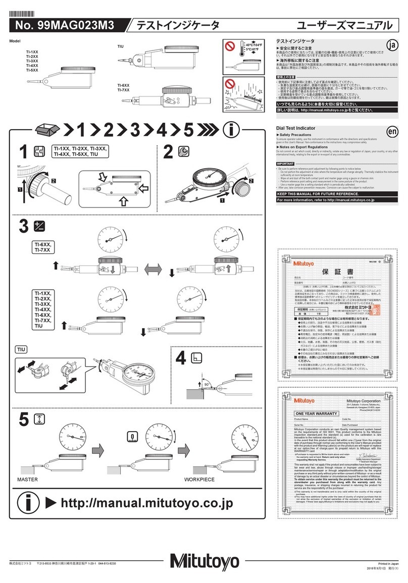
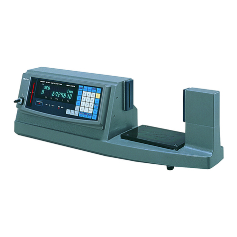
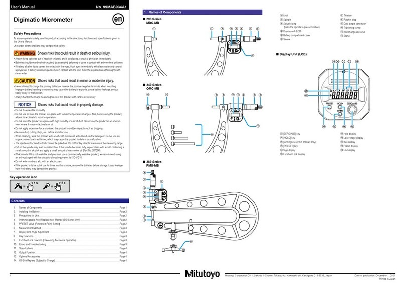
Mitutoyo IMZ-MJ User manual

Mitutoyo Corporation 20-1, Sakado 1-Chome, Takatsu-ku, Kawasaki-shi, Kanagawa 213-8533, Japan Date of publication: December 1, 2021
Printed in Japan
1
1. Names of Components
■Extension Rod Type Inside Micrometer (IMZ-MJ)
⑯
⑰
⑫
⑬ ⑭
④
③
⑮
①②
⑩
⑨⑪
■Extension Pipe Type Inside Micrometer (IMJ-MJ)
⑤
⑭⑬
⑫
⑥⑦⑧⑩
⑨⑪
⑮
⑯
⑰
For Extension Rod Type Inside
Micrometer (IMZ-MJ)
①Extension rod
②Cap
③Adjustment anvil
④Adjustment nut
For Extension Pipe Type Inside
Micrometer (IMJ-MJ)
⑤Extension pipe
⑥Adjustment anvil
⑦Adjustment nut
⑧Adjustment rod
Common
⑨Output connector
⑩Battery compartment cover
⑪Cover
⑫Swivel clamp
⑬Sleeve
⑭Thimble
⑮Waterproof mark
⑯LCD body
⑰Display unit
■Display Unit (LCD)
⑲⑳ ⑱
21
22
23
24 25 26 27 28
⑱[HOLD] key
⑲[ZERO/ABS] key
⑳[PRESET] key
㉑Sign display
㉒Function Lock display
㉓Hold display
㉔[in/mm] key (in/mm products only)
㉕Low voltage display
㉖INC display
㉗Preset display
㉘Unit display
2. Installing the Battery
When attaching the battery compartment cover, be sure to attach the gasket properly. The
product may display an error or malfunction if the battery compartment cover or gasket is not
mounted correctly.
Tips
• Be sure to use SR44 (silver oxide button battery part No. 938882) for the battery.
• Do not rotate the thimble until the count is displayed. Initial setting of the electrical components
may fail, or the product may not count normally. If you mistakenly move the thimble, reinstall the
battery.
• The battery supplied is for confirming the functions and performance of the product. Note that
this battery may not fulfill the predetermined life.
• Malfunction or damage due to depleted batteries, etc. is not covered by the warranty.
• Follow local rules and regulations regarding battery disposal.
Safety Precautions
To ensure operator safety, use this product in conformance with the directions, functions
and specifications given in this User's Manual.
Use under other conditions may compromise safety.
•
Always keep batteries out of reach of children, and if swallowed, consult a physician immediately.
• Batteries should never be short-circuited, disassembled, deformed or come in contact with
extreme heat or flames.
• If battery alkaline liquid comes in contact with the eyes, flush eyes immediately with clean
water and consult a physician. If battery alkaline liquid comes in contact with the skin,
flush the exposed area thoroughly with clean water.
Never attempt to charge the primary battery or reverse the positive-negative terminals
when mounting. Improper battery handling or mounting may cause the battery to explode,
cause battery leakage and/or serious bodily injury or malfunctioning.
• Do not disassemble or modify.
• Do not use or store the product in a place with sudden temperature changes. Adapt the
product to ambient temperature before use.
• Do not store the product in a place with high humidity or a lot of dust.
• Firmly close the battery compartment cover if the product is used in a place where it is
directly exposed to splashes of coolant, etc. When mounting the output cable and cover,
firmly tighten the fixing screws so that there is no gap. As well, clean and apply anti-rust
treatment after use. Rust may cause malfunction.
• Do not use submerged, as coolant ingress cannot be completely prevented. Complete
prevention of coolant ingress, etc., may also not be possible if the product is used in
locations exposed to direct jets of liquid.
• Do not apply excessive force or subject to sudden impacts such as dropping.
• When cleaning, wipe this product with a soft cloth moistened with diluted neutral
detergent. Do not use an organic solvent such as thinner, which may cause the product to
deform or malfunction.
• Do not write numbers, etc. with an electric pen.
• If the product is to be out of use for three months or more, remove the battery before
storage. Liquid leakage from the battery may damage the product.
• Do not pry out or suspend the product while it is inserted inside the workpiece.
Coolant-proof Extension Rod Type
Inside Micrometer IMZ-MJ
Coolant-proof Extension Pipe Type
Inside Micrometer IMJ-MJ
User's Manual No. 99MAB030A2
Contents
1. Names of Components ............................................................................................ Page 1
2. Installing the Battery ................................................................................................ Page 1
3. Precautions for Use ................................................................................................. Page 2
4. Reference Point Setting .......................................................................................... Page 2
5. Measurement Method ............................................................................................. Page 3
6. Key Functions .......................................................................................................... Page 3
7. Function Lock Function (Preventing Accidental Operation) .................................... Page 3
8. Errors and Troubleshooting ..................................................................................... Page 3
9. Mounting/Removing Rods (Pipes) ........................................................................... Page 3
10. Specifications .......................................................................................................... Page 3
11. Output Function ....................................................................................................... Page 3
12. Options .................................................................................................................... Page 4
13. Off-Site Repairs (Subject to Charge) ....................................................................... Page 4
Key operation icon
=
> 2 s
=
< 1 s
en
Mitutoyo Corporation 20-1, Sakado 1-Chome, Takatsu-ku, Kawasaki-shi, Kanagawa 213-8533, Japan Date of publication: December 1, 2021
Printed in Japan
2
The battery is not installed into the product at purchase. Install the battery as follows.
1Use the supplied Phillips screwdriver (No.05CAA952) to loosen and remove the battery
compartment cover fixing screws (M1.7 x 0.35 x 4/No.04AAB541).
2If replacing an existing battery, remove the old battery.
3Insert the battery (SR44) with the positive side facing upward.
Confirm that the gasket (No.05SAA372) is installed correctly in the proper position.
4
Place the battery compartment cover over the battery compartment and hold down the edge by
hand while making sure there is no gap between the cover and body, and then tighten it using
the screws.
》  The "------" display blinks.
5Press the [PRESET] key.
》  Count display appears and counting starts.
PRESET
3
4
1
5
①
+ -
+ terminal
- terminal
SR44
②
SR44
Tips
• Re-installing the battery will erase the PRESET value (reference point) position. Perform
reference point setting again (refer to "4. Reference Point Setting").
• If an abnormal display is shown, such as an error display or not counting, etc., try removing the
battery and reinstalling.
3. Precautions for Use
■Precautions for Measurement
•
This product, which is not equipped with a constant pressure device, is configured with heavier
operation than normal outside micrometers. The interior hydraulic oil will increase in viscosity if
used in low temperatures or left unused for a long time, and operation may feel heavier. In this
case, operate the thimble at full stroke several times to recover normal operation.
•
Use caution when measuring magnetized workpieces. If the product becomes magnetized,
measurement results may be affected.
■Precautions after Use
• After use, clean the entire product and check that none of the parts are damaged.
•
If using in places exposed to water-based cutting fluid, always apply anti-rust treatment after cleaning.
• If the product is to be out of use for three months or more, remove the battery before storage.
4. Reference Point Setting
Set an arbitrary preset value (reference point registration) prior to setting the reference point
(reference point setting).
•
Be sure to follow the procedure below to confirm and set the reference point prior to measuring.
•
When setting the reference point for this product, make sure to use a calibrated gage (setting ring, etc.).
• Remove any dirt or oil from the measuring surfaces of the gage and product prior to
setting the reference point.
•
Use the same orientation and conditions when measuring and setting the reference point.
• The preset value is within 999.999 mm (for metric products). To measure over 1000
mm, adjust the preset switch so that 1000 mm is 0 mm.
1) Reference point registration
Register (preset) the gage dimensions to the product. Two preset values (P1 and P2) can be
registered to the product.
Tips
Press and hold the [HOLD] key to switch between P1 and P2.
<Example> Registering 200.000 mm to P1
1 Briefly press the [PRESET] key.
》 
The previously registered number is displayed and [P1] blinks.
Tips
•
Zero will be displayed immediately after replacing the battery.
• If [P2] is blinking, press and hold the [HOLD] key to
cause [P1] to blink.
2Press and hold the [PRESET] key.
》  The sign blinks.
Tips
Briefly press the [PRESET] key to switch between [+]
and [-].
3Press and hold the [PRESET] key.
》  The number on the left blinks.
Tips
The numbers will switch in order from [0] to [1] to [2] up to [9]
and then [0] each time the [PRESET] key is briefly pressed.
4 Briefly press the [PRESET] key until [2] is displayed.
5Press and hold the [PRESET] key.
》  The number in the next digit blinks.
6Repeat steps 4and 5, so that [0] and [0] are
displayed for each digit.
7Press and hold the [PRESET] key until [P1] blinks.
8 Briefly press the [PRESET] key.
》  [P1] goes out and registration is complete.
1
PRESET
2
PRESET
3
PRESET
4
PRESET
5
PRESET
6
PRESET
PRESET
PRESET
7
PRESET
8
PRESET
Tips
•
To stop reference point registration, press the [ZERO/ABS]
key to return to the original display value.
• The display will not change during registration, even if
the thimble is rotated.
2) Reference point setting
1Remove any dirt or dust from the measuring surfaces of
the gage and the product.
2Set the dimension of the product slightly smaller than
that of the gage, and then slowly insert it into the gage.
3Rotate the thimble and bring the measuring surface
gently into contact with the gage.
4Move it in the direction of the arrow in Figure 1 within a
cross-section perpendicular to the axis to determine the
highest point (refer to Figure 1).
5
Move it in the direction of the arrow in Figure 2 with
regard to the axis to determine the lowest point (refer to
Figure 2).
6 Briefly press the [PRESET] key.
》  [P1] or [P2] blinks, and the registered preset value
(zero if not registered) is displayed.
Tips
• Press and hold the [HOLD] key to switch between P1
and P2.
• To change the preset value, refer to steps 2through
8in "1) Reference point registration".
7 Briefly press the [PRESET] key.
》  [P1] or [P2] goes out.
To use thimble graduations as well, set using the procedure
below.
8Perform steps 1through 4, and then use a hex
wrench to loosen the setting screw.
9Slightly rotate the sleeve and align it with the proper
display value.
10
Use the hex wrench to tighten the setting screw and fix
the sleeve.
11
Perform steps 1through 5, and confirm that the
proper number is displayed.
If the proper number is displayed, setting is complete. If it is
not displayed, repeat steps 8through
10
.
Tips
• The display of this product automatically turns off if not
used for 20 minutes or more. To display again, either
rotate the thimble or press the [ZERO/ABS] key.
• If the [PRESET] key is accidentally pressed during
measurement, press the [ZERO/ABS] key to return to
the former state. If this does not enable the product to
recover, perform the reference point setting procedure
once more.
• Once the product has been inserted, do not move it
until the reference point has been set.
Key operation icon
=
> 2 s
=
< 1 s
5
45
0
4
5
Figure 1. Top view
Figure 2. Side view
8
9
10
Mitutoyo Corporation 20-1, Sakado 1-Chome, Takatsu-ku, Kawasaki-shi, Kanagawa 213-8533, Japan Date of publication: December 1, 2021
Printed in Japan
3
5. Measurement Method
Be sure to perform reference point setting before measurement.
1Insert the product into the workpiece, and then retract the thimble until it makes contact with the
measurement location.
2Using the same orientation and conditions as for reference point setting, move the product left
and right within a cross-section perpendicular to the axis to determine the highest point, while at
the same time moving it forward and back versus the axis to determine the lowest point. Then
make contact with the workpiece and read the display value (refer to Figures 1 and 2 in
"2) Reference point setting" in "4. Reference Point Setting").
6. Key Functions
■[ZERO/ABS] Key
1 Briefly press the [ZERO/ABS] key.
》  [INC] is displayed, and the display
is set to zero.
2Press and hold the [ZERO/ABS] key
(for at least 2 seconds).
》 
[INC] goes out, and the length
from the reference point (anvil
measuring surface) is displayed.
■[HOLD] Key
1Press the [HOLD] key.
》  [H] is displayed, and the display
value is held.
2Press the key again to release the value.
■[in/mm] Key (in/mm products only)
• Press the [in/mm] key.
》 [in] and [mm] switch back and forth each time the
key is pressed.
7. Function Lock Function (Preventing Accidental Operation)
This product has the Function Lock function, which disables the PRESET function and ZERO/ABS
function in order to avoid accidental changes to the reference point position.
Setting the Function Lock causes [ ] on the LCD to light up and disables the [PRESET] key, [ZERO/ABS]
key, and [in/mm] key (in/mm products only), with only the hold operation function enabled.
1First press and hold the [HOLD] key, and then additionally press and hold the [ZERO/ABS] key
(for at least 2 seconds).
》  [H] display and [ ] display light up in sequence ([H] turns off first).
2Perform the same operation to release the Function Lock.
21
+
ZERO/ABSHOLD
+
ZERO/ABSHOLD
=
> 2 s
=
< 1 s
Key operation icon
ZERO/ABS ZERO/ABS
1
2
HOLD HOLD
12
in / mm
8. Errors and Troubleshooting
Error Display Causes and Countermeasures
Power Voltage Drop
The battery voltage is low. Replace the battery promptly.
Counting Error
A counting error has occurred due to excessive speed or noise.
Try removing the battery and reinstalling.
Counting Error
Initial setting of the electrical components failed, or a counting
error has occurred due to a sensor signal error. Try removing the
battery and reinstalling.
Display Overflow
The display value exceeds ±999.999. Rotate the thimble in the
opposite direction so that it starts counting again correctly.
9. Mounting/Removing Rods (Pipes)
Attach extension rods (or pipes) to measure the workpiece, according to the length of the workpiece.
Attach extension rods to the Extension Rod Type Inside Micrometer (IMZ-MJ), or extension pipes
to the Extension Pipe Type Inside Micrometer (IMJ-MJ).
When mounting or removing extension rods (pipes), do not grasp the display unit. Otherwise,
damage may result.
Be sure to perform reference point setting after mounting or removing rods (pipes).
Use the following procedure to install or remove rods (pipes).
■For Extension Rod Type Inside Micrometer (IMZ-MJ)
1
Wipe clean all extension rods to be mounted as well as the connection area on the body, to remove
any debris or dust.
2Loosen and remove the cap by hand.
3Mount the extension rod by manually screwing it into the place where the cap was.
4Mount the cap by screwing it onto the end of the extension rod.
■For Extension Pipe Type Inside Micrometer (IMJ-MJ)
Use the same procedure as for IMZ-MJ. However, IMJ-MJ uses an adjustment rod instead of a cap.
Use the same procedure to remove the extension rod (pipe).
Display unit
Cap (adjustment rod)
Extension rod (pipe)
Loosen
Tighten
10. Specifications
• Spindle feed error (20 °C) : 3 μm
0.00015 in (in/mm products only)
• Resolution : 0.001 mm
0.00005 in (in/mm products only)
• Display unit : LCD (6-digit and minus sign)
• Power supply : Button type silver-oxide battery (SR44 No.938882), x1
• Battery life : 1.2 years
• Operating temperature : 5 °C to 40 °C
• Storage temperature : -10 °C to 60 °C
• Standard accessories : Wrench, Phillips screwdriver (No. 05CAA952)
• IP protection level : IP65 (refer to IEC60529 for details).
Dust resistance (level 6) : No ingress of dust allowed.
Protection against water jets (level 5) : Water projected by a nozzle from any direction
shall have no harmful effects.
•
CE marking/UKCA marking
: EMC Directive/Electromagnetic Compatibility Regulations: EN 61326-1
Immunity test requirement : Annex A Table A.1
Emission limit : Class B
:
RoHS Directive/The Restriction of the Use of Certain Hazardous Substances
in Electrical and Electronic Equipment Regulations: EN IEC 63000
11. Output Function
■Display Value External Output
The display value can be output to a device by connecting the product and the external device with
a connection cable (option).
■Connection Cable Installation Method
• Always use the 0-size Phillips screwdriver (No.05CZA619) supplied with the connection cable
(option) when installing/removing screws, and tighten with a torque of 5 to 8 cN•m or so.
Otherwise, it may cause damage.
• When connecting the connection cable, ensure that the connector gasket does not protrude. If
the connector gasket is not installed properly, waterproof functionality may decrease and lead
to malfunctions.
•
When connecting the connection cable, pay attention to the connector direction. Otherwise,
damage may result.
Tips
Note that using this product in a location with high noise may cause malfunctions (flickering or errors).
Mitutoyo Corporation 20-1, Sakado 1-Chome, Takatsu-ku, Kawasaki-shi, Kanagawa 213-8533, Japan Date of publication: December 1, 2021
Printed in Japan
4
1
Use the Phillips screwdriver supplied with the connection cable to remove the cover fixing screws
(M1.7 x 0.35 x 2.5, No.04AAB543).
2Remove the cover.
3Check that the connector gasket (No.09GAA374) is correctly installed at the proper position
(do not remove the connector gasket).
4Mount the connection cable plug.
5 While holding in the connection cable plug by hand, tighten the fixing screws.
Tips
•
Ensure that there is no gap between the connection cable plug and the body connector.
• The display value hold (refer to "■[HOLD] Key" in "6. Key Functions") will be released if output
to an external device.
1
2
4
5
■Output Data Format
(1) Output
order
(2) All "F"
(3) Sign
(4) Measured
value
(5) Decimal
point
(6) Unit
■Timing Chart
200 ms
0.14 ms (Typ:0.122 ms)
0.27 ms (Typ:0.244 ms)
80 ms
0 ms
0.11 ms
0.11 ms
0.22 ms
T1
T2
T3
T4
T5
*1: DATAsw is LOW while the data output key is being pressed.
*2: The time T5 until DATAsw goes to the LOW level and REQ is input is determined by the data processing
device performance.
(1)
MSD LSD
(5)
(2)
(1111)
(4)
(3)
+:0(0000)
–:8(0001)
3(1100)
4(0010)
5(1010)
(6)
mm:0(0000)
in:1(1000)
12. Options
• Connection cable (1 m): No.05CZA662
• Connection cable (2 m): No.05CZA663
For options other than the above, refer to the General Catalog.
13. Off-Site Repairs (Subject to Charge)
Off-site repair (subject to charge) is required in the case of the following malfunctions. Please
contact the agent where you purchased the product or a Mitutoyo sales representative.
• Count value error/faulty operation
If the thimble of this product is retracted too far, the internal sensor will be damaged. This may
cause count errors or faulty operation.

This manual suits for next models

1

Other Mitutoyo Measuring Instrument manuals

Mitutoyo ID-F125 User manual

Mitutoyo

Mitutoyo ID-F125 User manual

Mitutoyo IT-012U User manual

Mitutoyo

Mitutoyo IT-012U User manual

Mitutoyo LG200 User manual

Mitutoyo

Mitutoyo LG200 User manual

Mitutoyo LGH Series User manual

Mitutoyo

Mitutoyo LGH Series User manual

Mitutoyo SURFTEST SV-3100 User manual

Mitutoyo

Mitutoyo SURFTEST SV-3100 User manual

Mitutoyo EJ-102N User manual

Mitutoyo

Mitutoyo EJ-102N User manual

Mitutoyo ID-C112GXB User manual

Mitutoyo

Mitutoyo ID-C112GXB User manual

Mitutoyo Digimatic MDC-S User manual

Mitutoyo

Mitutoyo Digimatic MDC-S User manual

Mitutoyo LGF-110ZL-B User manual

Mitutoyo

Mitutoyo LGF-110ZL-B User manual

Mitutoyo 500-712-20 User manual

Mitutoyo

Mitutoyo 500-712-20 User manual

Mitutoyo ID-H0530 User manual

Mitutoyo

Mitutoyo ID-H0530 User manual

Mitutoyo 500-150-30 User manual

Mitutoyo

Mitutoyo 500-150-30 User manual

Mitutoyo CONTRACER CV-2100 User manual

Mitutoyo

Mitutoyo CONTRACER CV-2100 User manual

Mitutoyo ID-C Series User manual

Mitutoyo

Mitutoyo ID-C Series User manual

Mitutoyo ID-CNX Series User manual

Mitutoyo

Mitutoyo ID-CNX Series User manual

Mitutoyo LGB2 User manual

Mitutoyo

Mitutoyo LGB2 User manual

Mitutoyo 99MAB034A1 User manual

Mitutoyo

Mitutoyo 99MAB034A1 User manual

Mitutoyo SJ-210 User manual

Mitutoyo

Mitutoyo SJ-210 User manual

Mitutoyo LSM-9506 User manual

Mitutoyo

Mitutoyo LSM-9506 User manual

Mitutoyo ID-SX User manual

Mitutoyo

Mitutoyo ID-SX User manual

Mitutoyo QM-Height User manual

Mitutoyo

Mitutoyo QM-Height User manual

Mitutoyo HDS-H30C User manual

Mitutoyo

Mitutoyo HDS-H30C User manual

Mitutoyo HDM-30AX User manual

Mitutoyo

Mitutoyo HDM-30AX User manual

Mitutoyo CG-S10A User manual

Mitutoyo

Mitutoyo CG-S10A User manual

Popular Measuring Instrument manuals by other brands

Honeywell DVC100 (M) MK2 installation guide

Honeywell

Honeywell DVC100 (M) MK2 installation guide

Benthowave Instrument BII7120 Series manual

Benthowave Instrument

Benthowave Instrument BII7120 Series manual

Hanna Instruments HI 717 quick start guide

Hanna Instruments

Hanna Instruments HI 717 quick start guide

PCB Piezotronics JM352C68 Installation and operating manual

PCB Piezotronics

PCB Piezotronics JM352C68 Installation and operating manual

LaserLiner MeterMaster Plus quick start guide

LaserLiner

LaserLiner MeterMaster Plus quick start guide

OEG 310 821 216 instruction manual

OEG

OEG 310 821 216 instruction manual

Smart Storm Universal Smart Meter instruction manual

Smart Storm

Smart Storm Universal Smart Meter instruction manual

Vetek MO.DTR.526.R6 operating manual

Vetek

Vetek MO.DTR.526.R6 operating manual

ThermoWorks ThermaQ 2 operating instructions

ThermoWorks

ThermoWorks ThermaQ 2 operating instructions

Landis+Gyr ULTRAHEAT T230 manual

Landis+Gyr

Landis+Gyr ULTRAHEAT T230 manual

MKS Granville-Phillips Mini-Convectron 275... instruction manual

MKS

MKS Granville-Phillips Mini-Convectron 275... instruction manual

Saluki S3602 Series user manual

Saluki

Saluki S3602 Series user manual

TriBrer AOP110 user guide

TriBrer

TriBrer AOP110 user guide

IA Networks Technology IPM3400 user guide

IA Networks Technology

IA Networks Technology IPM3400 user guide

Jesco FLOWCON Operation & maintenance instructions

Jesco

Jesco FLOWCON Operation & maintenance instructions

Vega VEGAPULS 62 operating instructions

Vega

Vega VEGAPULS 62 operating instructions

Ditel DINOS Series Quick installation guide

Ditel

Ditel DINOS Series Quick installation guide

HAZ-DUST HD-1100 instructions

HAZ-DUST

HAZ-DUST HD-1100 instructions

manuals.online logo
manuals.online logoBrands
  • About & Mission
  • Contact us
  • Privacy Policy
  • Terms and Conditions

Copyright 2025 Manuals.Online. All Rights Reserved.