Air-Bus CARK-10 User manual

IH - PS11438BMLAE01
09/2017
EN
DA
ET
FI
NO
SV
Car Kit
CARK-10
- Installation Guide
Bilsæt
CARK-10
- Installationsvejledning
Autokomplekt
CARK-10
- Paigaldusjuhend
CARK-10
-autosarja - Asennusopas
Bilkit
CARK-10
- Installasjonsveiledning
Komplett bilmonteringssats
CARK-10
- Installationsguide
print.book Page 1 Jeudi, 28. septembre 2017 10:41 10

09/2017
IH - PS11438BMLAE01
Copyright
®
2015 - 2017 Airbus DS SLC. All rights reserved.
EN
DA
ET
FI
NO
SV
Version 2
HR8890AA
print.book Page 2 Jeudi, 28. septembre 2017 10:41 10

IH - PS11438BMLAE01
09/2017
1/8
Copyright
®
2015 - 2017 Airbus DS SLC. All rights reserved.
EN
Car Kit CARK-10 - Installation Guide
Introduction
This installation guide has been prepared to provide the basic information necessary to
install CARK-10. This guide is not intended to be definitive, because different types and
models of vehicles will require different installation work. The information given is for
general guidance only.
The terms of warranty demand that this car kit be installed by an experienced installer
and that only specified parts are used. An end-user should never attempt to install this
car kit without professional assistance as the installation requires special tools and
knowledge.
Please refer to the radio’s User Guide for instructions on the radio’s operation, care and
maintenance, including important safety information.
Note:
Read the warnings below before beginning the installation procedure.
WARNINGS
1. ENSURE THAT THE VEHICLE’S BATTERY IS DISCONNECTED BEFORE YOU
START THE INSTALLATION PROCEDURE, AND THAT IT REMAINS
DISCONNECTED DURING THE PROCEDURE.
2. DO NOT SMOKE OR USE OPEN FLAMES WHEN WORKING NEAR THE
VEHICLE’S FUEL SYSTEM.
3. ENSURE THAT THE VEHICLE’S ELECTRICAL CABLES, HYDRAULIC LINES,
FUEL LINES, AND SAFETY EQUIPMENT ARE NOT DAMAGED DURING
INSTALLATION.
4. ENSURE THAT NORMAL CONTROL AND OPERATION OF THE VEHICLE IS
NOT IMPAIRED BY THE INSTALLATION, PARTICULARLY VISIBILITY, THE
BRAKES AND STEERING. ENSURE THAT AIRBAG OPERATION IS NOT
OBSTRUCTED.
5. ELECTRONIC AND OTHER SOPHISTICATED SYSTEMS (e.g. SPEED
CONTROL, ABS ANTI-LOCK BRAKE, FUEL INJECTION-, NAVIGATION-, AND
AIR-BAG SYSTEMS) ARE RELATIVELY IMMUNE TO MALFUNCTION CAUSED
BY NEARBY RADIO TRANSMISSIONS. HOWEVER, SHOULD YOU
EXPERIENCE FALSE OPERATION OF THESE SYSTEMS OR ARE IN ANY
DOUBT WHATSOEVER AS TO THEIR FUNCTIONALITY, PLEASE CONSULT
THE VEHICLE’S DEALER.
6. THE CAR KIT IS SUITABLE FOR USE ONLY IN VEHICLES WITH A 12 V
NEGATIVE GROUNDING. USE ON OTHER SUPPLY VOLTAGES OR
ALTERNATIVE POLARITY WILL DAMAGE THE EQUIPMENT.
7. THE RADIO SHOULD NOT BE LEFT SWITCHED ON FOR EXTENDED PERIODS
WITHOUT RUNNING THE VEHICLE’S ENGINE. FAILURE TO COMPLY COULD
DRAIN THE VEHICLE’S BATTERY.
8. ONLY QUALIFIED PERSONNEL MAY INSTALL OR REPAIR THIS PRODUCT.
print.book Page 1 Jeudi, 28. septembre 2017 10:41 10

2/8
09/2017
IH - PS11438BMLAE01
Copyright
®
2015 - 2017 Airbus DS SLC. All rights reserved.
EN
Car Kit CARK-10 - Installation Guide
Components of CARK-10
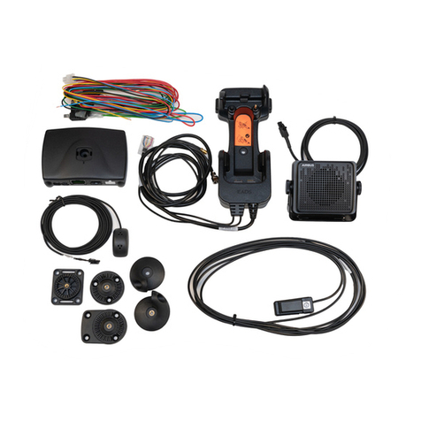
Fig. 1. Installation without the DTC-1 Adapter Cable
The CARK-10 includes the above parts. Please note that the items enclosed within
broken lines are not supplied with CARK-10.
print.book Page 2 Jeudi, 28. septembre 2017 10:41 10

IH - PS11438BMLAE01
09/2017
3/8
Copyright
®
2015 - 2017 Airbus DS SLC. All rights reserved.
EN
Car Kit CARK-10 - Installation Guide
Fig. 2. Installation using the DTC-1 Adapter Cable
Please note that all items shown above are included in CARK-10 except those enclosed
within broken lines.
*Two of these accessories can be connected simultaneously.
print.book Page 3 Jeudi, 28. septembre 2017 10:41 10

4/8
09/2017
IH - PS11438BMLAE01
Copyright
®
2015 - 2017 Airbus DS SLC. All rights reserved.
EN
Car Kit CARK-10 - Installation Guide
Component Parts
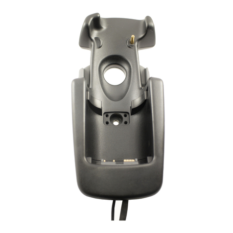
Advanced Active Holder MCR-6
The holder for the radio is attached to the vehicle’s interior in a convenient position using
the swivel mount HHS-15. The mounting is secured with a screw (included with HHS-15).
The screw recess is covered with the rubber plate.
The cable with the plug-in connector from MCR-6 connects to the
PHONE
socket in HFU-
2T. (The other 2 cables from MCR-6 connect to external antennas.)
Swivel Mount HHS-15 and Mounting Plate MKU-1
HHS-15 is a swivel mount which allows for adjustable fixing. MKU-1 is a fixed position
mounting plate.
Advanced HF Unit HFU-2T
The handsfree unit HFU-2T is attached to the vehicle interior using the mounting plate
MKU-1. The mounting is secured with a screw (included with MKU-1).
Power Cable PCH-4J
The power cable connects to the
DC
socket in HFU-2Tand to the vehicle’spower supply.
See the ”Installation” section for more information.
HF Microphone MP-3
The HF microphone connects to the
MIC
socket in HFU-2T. Push the plug to lock it firmly
in place.
HF Speaker HFS-12
The HF speaker connects to the
SPEAKER
socket in HFU-2T. Push the plug to lock it
firmly in place.
Adapter Cable DTC-1
The DTC-1 adapter cable connects to the HFU-2T DATA/HANDSET socket. It provides
for the possibility of connecting to two out of three possible accessories: PTT-1, HSU-1T
and DLR-3T. It comprises specified sockets for DATA and HANDSET connection.
Note that if only one of these three accessories is used, it must be connected directly to
the HFU-2T without using the DTC-1!
External Push to Talk Key PTT-1
The external push to talk key is to be used during a one-way call. The key connects
directly to the HFU-2T DATA/HANDSET socket or to either socket in the DTC-1 Adapter
cable (please refer to DTC-1).
Note that the external push to talk key is not allowed to be installed to a vehicle control
device!
Data Adapter Cable DLR-3T (not supplied)
The data adapter cable enables RS232 data connection totheradio. The cableconnects
directly to the HFU-2T DATA/HANDSET socket or to the DTC-1 adapter cable DATA
socket (please refer to DTC-1). For more information, please refer to the user guide for
the data adapter cable.
External Mobile Antenna (not supplied)
An external TETRA-band antenna is recommended for the car kit. It connects to MCR-6.
print.book Page 4 Jeudi, 28. septembre 2017 10:41 10

IH - PS11438BMLAE01
09/2017
5/8
Copyright
®
2015 - 2017 Airbus DS SLC. All rights reserved.
EN
Car Kit CARK-10 - Installation Guide
Handset HSU-1T (not supplied)
Thehandset HSU-1Toffersmoreprivacy duringa call.Duringa one-waycall thePTT key
must be used. It connects to the
DATA/HANDSET
socket of HFU-2T or to the DTC-1
adapter cable HANDSET socket (please refer to DTC-1). For more information, please
refer to the user guide for the handset.
Installation
For an example of installation locations, please see the cover.
Note:
Ensure that the battery of the vehicle is disconnected before you start the
installation or start making changes to the installations, and that it remains disconnected
during the installation procedure.
The HFU-2T and the different parts are connected as mentioned in the ”Component
Parts” section.
There are some important aspects that require special attention in positioning car kit
accessories.
The location of the holder should be selected so that the radio's display is easily visible
and that the driver’s attention is not distracted. The location of the holder should allow the
driver to easily reach the keypad. Under no circumstances should the holder in any way
prevent the driver from controlling or operating the vehicle.
The HF microphone should be installed according to the directions in the separate
microphone installation guide. Ensure that the microphone is as close to the driver’s
mouth as possible, and attached to a surface that is mechanically quiet. The microphone
should be mounted at least 3 ft/1 m away from the handsfree unit speaker to avoid
acoustic feedback.
Ensure that the cables are routed as far away as possible from the vehicle’s electronic
systems. This is to prevent interference. Also, ensure that the cables are not subjected to
undue mechanical stress e.g. under seats or against sharp edges.
PCH-4J
Thecablesfrom PCH-4Jare colourcoded. Theyarelistedin thefollowingtablein column
A and each cable should be connected to the corresponding item listed in column B.
A B
Red cable (with 2 amp fuse) The + voltage on the vehicle’s power supply.
Black cable The negative GND connection.
Blue cable (with 1 amp fuse) The +12 V voltage controlled by the vehicle’s
ignition key. (See section ”Ignition Sense IGNS”.)
Yellow cable Used for car radio muting (XCRM) and is connected
to the car radio. The line goes down to 0 volts during
a call. See section ”Car Radio Muting CRM”.
Green cable (with 1 amp fuse) The motor antenna (AMC). The voltage in this
output is +12 V whenever the phone is on. See
section ”Antenna Motor Control AMC”.
print.book Page 5 Jeudi, 28. septembre 2017 10:41 10

6/8
09/2017
IH - PS11438BMLAE01
Copyright
®
2015 - 2017 Airbus DS SLC. All rights reserved.
EN
Car Kit CARK-10 - Installation Guide
Ignition Sense IGNS
The ignition sense feature prevents your car kit from draining the car battery by executing
an auto power off 20 seconds after the ignition key has been turned off. The blue cable
from PCH-4J is used for the ignition sense feature. The use of ignition sense is
recommended to prevent accidental draining of the car’s battery. The cable is connected
via a 1-A fuse to a 12- V supply that is controlled by the ignition key. Do not connect it
directly to the high voltage sections of the ignition circuit.
Car Radio Muting CRM
The car kit offers a feature that can mute the car radio automatically during a
conversation. The following is the circuit diagram for CRM.
Another possibility is to use a special muting unit, which mutes the radio by connecting
load resistors to the speaker lines of the car radio.
Antenna Motor Control AMC
The antenna motor control may be used to turn different devices on and off. The
maximum output current is 200 mA; therefore, for example, a motorized antenna must be
controlled via a relay, see diagram below.
All installations should take into account any special requirements of the customer.
However, should the customer require an installation that is illegal or unsafe these facts
must be pointed out to the customer and a policy of non-compliance adopted.
CAR
RADIO
Relay (12 V)
12 V d.c.
12 V d.c.
Supply for
car radio
Fuse 200 mA
(not supplied)
To XCRM line
(yellow wire)
85
87
87A
30
86
GND
87
Relay (12 V)
12 V d.c.
Fuse 1 A
85
87A
30
86
GND
CONTROLLED
DEVICE e.g.
MOTOR ANTENNA
GND
Supply for
device
From AMC line
(green wire)
print.book Page 6 Jeudi, 28. septembre 2017 10:41 10

IH - PS11438BMLAE01
09/2017
7/8
Copyright
®
2015 - 2017 Airbus DS SLC. All rights reserved.
EN
Car Kit CARK-10 - Installation Guide
Testing
Once installed, the equipment should be tested to ensure that it is operating satisfactorily
and that the position of the units does not in any way impair the driver’s ability to control
and operate the vehicle.
print.book Page 7 Jeudi, 28. septembre 2017 10:41 10

IH - PS11438BMLAE01
09/2017
1/8
Copyright
®
2015 - 2017 Airbus DS SLC. All rights reserved.
1
DA
Bilsæt CARK-10 - Installationsvejledning
Indledning
Formålet med denne installationsvejledning er at give de grundlæggende oplysninger,
der er nødvendige for at installere CARK-10. Denne vejledning er ikke endelig, da
køretøjer af forskellige typer og modeller kræver forskellige installationer. De angivne
oplysninger er kun til generel vejledning.
Vilkårene for garantien kræver, at dette bilsæt installeres af en erfaren installatør, og at
kun de angivne dele benyttes. En slutbruger må aldrig forsøge at installere dette bilsæt
uden professionel assistance, da installationen kræver særligt værktøj og specialviden.
Læs brugervejledningen til radioen for at få vejledning i, hvordan radioen betjenes,
håndteres og vedligeholdes, herunder vigtige sikkerhedsoplysninger.
Bemærk! Læs advarslerne nedenfor, før installationen påbegyndes.
ADVARSLER
1. SØRG FOR, AT KØRETØJETS BATTERI ER FRAKOBLET, FØR DU STARTER
INSTALLATIONEN, OG AT DET FORBLIVER FRAKOBLET UNDER HELE
INSTALLATIONEN.
2. RYGNING ELLER ÅBEN ILD ER FORBUDT I FORBINDELSE MED ARBEJDE
I NÆRHEDEN AF KØRETØJETS BRÆNDSTOFSYSTEM.
3. SØRG FOR, AT KØRETØJETS ELEKTRISKE KABLER, HYDRAULISKE
KABLER, BRÆNDSTOFKABLER OG SIKKERHEDSUDSTYR IKKE
BESKADIGES I FORBINDELSE MED INSTALLATIONEN.
4. SØRG FOR, AT NORMAL KONTROL OG BETJENING AF KØRETØJET IKKE
FORRINGES AF INSTALLATIONEN, ISÆRUDSYN, BREMSER OG STYRING.
SØRG FOR, AT KØRETØJETS AIRBAGS IKKE BLOKERES.
5. ELEKTRONIK OG ANDRE SOFISTIKEREDE SYSTEMER (f.eks.
FARTKONTROL, ABS-BREMSER, BRÆNDSTOFINDSPRØJTNINGS-
NAVIGATIONS- OG AIRBAGSYSTEMER) ER FORHOLDSVIS IMMUNE OVER
FOR FEJL, DER SKYLDES RADIOTRANSMISSIONER. HVIS DU ALLIGEVEL
OPLEVER DRIFTSFEJL MED DISSE SYSTEMER ELLER ER I TVIVL OM
DERES FUNKTIONALITET, SKAL DU KONTAKTE BILFORHANDLEREN.
6. BILSÆTTET ER KUN EGNET TIL BRUG I KØRETØJER MED EN 12 V NEGATIV
JORDFORBINDELSE. BRUG MED ANDEN SPÆNDING ELLER POLARITET VIL
RESULTERE I BESKADIGELSE AF UDSTYRET.
7. RADIOEN BØR IKKE VÆRE TÆNDT I LÆNGERE PERIODER, MENS
KØRETØJETS MOTOR ER SLUKKET. HVIS DETTE IKKE OVERHOLDES,
AFLADES KØRETØJETS BATTERI MULIGVIS.
8. KUN KVALIFICERET PERSONALE MÅ INSTALLERE ELLER REPARERE
DETTE PRODUKT.
print.book Page 1 Jeudi, 28. septembre 2017 10:41 10

2/8
09/2017
IH - PS11438BMLAE01
Copyright
®
2015 - 2017 Airbus DS SLC. All rights reserved.
1
DA
Bilsæt CARK-10 - Installationsvejledning
CARK-10-komponenter
Fig. 1. Installation uden adapterkablet DTC-1
CARK-10 indeholder delene ovenfor. Bemærk, at de elementer, der er angivet
i en boks med stiplede sider, ikke leveres sammen med CARK-10.
print.book Page 2 Jeudi, 28. septembre 2017 10:41 10

IH - PS11438BMLAE01
09/2017
3/8
Copyright
®
2015 - 2017 Airbus DS SLC. All rights reserved.
1
DA
Bilsæt CARK-10 - Installationsvejledning
Fig. 2. Installation vha. adapterkablet DTC-1
Bemærk, at alle de elementer, der er vist ovenfor, medfølger CARK-10. Det gælder
dog ikke dem, der er angivet i boks med stiplede sider.
*Det er muligt at tilslutte to tilbehørsdele samtidigt.
print.book Page 3 Jeudi, 28. septembre 2017 10:41 10

4/8
09/2017
IH - PS11438BMLAE01
Copyright
®
2015 - 2017 Airbus DS SLC. All rights reserved.
1
DA
Bilsæt CARK-10 - Installationsvejledning
Komponentdele
Avanceret, aktiv holder (MCR-6)
Holderen til radioen placeres indvendigt i køretøjet på et praktisk sted vha. det drejelige
HHS-15-beslag. Monteringen sikres med en skrue (medfølger HHS-15). Skruehovedet
dækkes med en gummiplade.
Kablet med stikket fra MCR-6 tilsluttes PHONE-stikket i HFU-2T. (De to andre kabler
fra MCR-6 tilsluttes eksterne antenner.)
Drejeligt beslag (HHS-15) og monteringsplade (MKU-1)
HHS-15 er et drejeligt beslag, der muliggør regulerbar fastgørelse. MKU-1 er en
monteringsplade med fast position.
Avanceret HF-enhed (HFU-2T)
Den håndfri enhed (HFU-2T) monteres indvendigt i køretøjet vha. Monteringspladen
MKU-1. Monteringen sikres med en skrue (medfølger MKU-1).
Strømkabel (PCH-4J)
Strømkablet skal tilsluttes DC-stikket i HFU-2T og køretøjets strømforsyning. Du kan
finde flere oplysninger under afsnittet ”Installation ”.
HF-mikrofon (MP-3)
HF-mikrofonen tilsluttes MIC -stikket i HFU-2T. Tryk på stikket for at låse det på plads.
HF-højttaler (HFS-12)
HF-højttaleren tilsluttes SPEAKER -stikket i HFU-2T. Tryk på stikket for at låse det på
plads.
Adapterkabel (DTC-1)
Adapterkablet (DTC-1) tilsluttes HFU-2T DATA/HANDSET-stikket. Dette giver
mulighed for at tilslutte to ud af tre mulige tilbehør: PTT-1, HSU-1T og DLR-3T. Det
omfatter specificerede stik til DATA- og HANDSET-tilslutning.
Bemærk, at hvis kun ét af disses tre tilbehør bruges, skal det sluttes direkte til HFU-2T
uden at bruge DTC-1!
Ekstern tast til trykog tal (PTT-1)
Den eksterne tast til tryk og tal bruges til envejsopkald. Tasten har forbindelse direkte
til HFU-2T DATA/HANDSET-stikket eller til et af stikkene i adapterkablet (DTC-1)
(se DTC-1).
Bemærk, at den eksterne tast til tryk og tal ikke må installeres i køretøjets
kontrolenhed!
Dataadapterkabel (DLR-3T) (medfølger ikke)
Med dataadapterkablet kan der oprettes en RS232-forbindelse til radioen. Kablet
sluttes direkte til HFU-2T DATA/HANDSET-stikket eller til DATA-stikket til
adapterkablet DTC-1 (se DTC-1). Du kan finde flere oplysninger ved at læse
brugervejledningen til dataadapterkablet.
Ekstern mobilantenne (medfølger ikke)
Vi anbefaler en ekstern TETRA-antenne til bilsættet. Den sluttes til MCR-6.
print.book Page 4 Jeudi, 28. septembre 2017 10:41 10

IH - PS11438BMLAE01
09/2017
5/8
Copyright
®
2015 - 2017 Airbus DS SLC. All rights reserved.
1
DA
Bilsæt CARK-10 - Installationsvejledning
Håndsæt HSU-1T (medfølger ikke)
Håndsættet HSU-1T giver bedre beskyttelse af personlige oplysninger under et opkald.
PTT-tasten skal bruges til envejsopkald. Kablet tilsluttes DATA/HANDSET-stikket
i HFU-2T eller HANDSET-stikket til adapterkablet DTC-1 (se DTC-1). Du kan finde
flere oplysninger ved at læse brugervejledningen til håndsættet.
Installation
Se forsiden for at se eksempler på installationssteder.
Bemærk! Sørg for, at køretøjets batteri er frakoblet, før du starter installationen eller
foretager ændringer af installationen, og at det forbliver frakoblet under hele
installationen.
HFU-2T og de forskellige dele tilsluttes som beskrevet i afsnittet ”Komponentdele ”.
Der er en række vigtige aspekter, der kræver særlig opmærksomhed ved placering af
bilsættets tilbehør.
Holderen skal placeres, så radioens display nemt kan ses, og så føreren ikke
forstyrres. Holderen bør placeres, så føreren nemt kan nå tastaturet. Holderen må
under ingen omstændigheder forhindre føreren i at styre eller betjene køretøjet.
HF-mikrofonen skal installeres som beskrevet i instruktionerne i den separate
installationsvejledning til mikrofonen. Sørg for, at mikrofonen er placeret så tæt på
førerens mund som muligt, og at den er fastgjort på en overflade uden mekanisk støj.
Mikrofonen bør monteres mindst 1 m fra højttaleren til den håndfri enhed for at undgå
akustiske forstyrrelser.
Sørg for, at kablerne trækkes så langt fra køretøjets elektroniske systemer som muligt.
Dette gøres for at forhindre interferens. Sørg desuden for, at kablerne ikke udsættes
for unødigt mekanisk belastning f.eks. under sæder eller mod skarpe kanter.
PCH-4J
Kablerne fra PCH-4J er farvekodede. Kolonne A i den følgende tabel indeholder en
liste over farvekoder. Hvert kabel skal sluttes til det tilsvarende element i kolonne B.
A B
Rødt kabel
(med sikring på 2 A) Den positive spænding i køretøjets strømforsyning.
Sort kabel Den negative GND-forbindelse.
Blåt kabel
(med sikring på 1 A) +12 V spænding, der styres af køretøjets
tændingsnøgle. (Se afsnittet ”Registrering af
tænding – IGNS ”.)
Gult kabel Bruges til at slå radioens lyd fra (XCRM) og sluttes
til bilradioen. Kablet går ned til 0 volt under et opkald.
Se afsnittet ”Slå radioens lyd fra – CRM ”.
Grønt kabel
(med sikring på 1 A) Motorantennen (AMC). Spændingen for dette output
er +12 V, når telefonen er tændt. Se afsnittet
”Styring af antennemotoren – AMC ”.
print.book Page 5 Jeudi, 28. septembre 2017 10:41 10

6/8
09/2017
IH - PS11438BMLAE01
Copyright
®
2015 - 2017 Airbus DS SLC. All rights reserved.
1
DA
Bilsæt CARK-10 - Installationsvejledning
Registrering af tænding – IGNS
Funktionen til registrering af tænding forhindrer, at bilsættet aflader bilbatteriet ved
at automatisk at slukke 20 sekunder efter tændingsnøglen slås fra. Det blå kabel fra
PCH-4J bruges til funktionen til registrering af tænding. Det anbefales at bruge
registrering af tænding for at undgå at aflade bilens batteri ved en fejl. Kablet sluttes via
en 1 A sikring til en 12 V forsyning, der styres af tændingsnøglen. Slut den ikke direkte
til højspændingsdelene af tændingskredsløbet.
Slå radioens lyd fra – CRM
Bilsættet indeholder en funktion, der automatisk kan slå radioens lyd fra under en
samtale. Nedenfor ses kredsløbsdiagrammet for CRM.
Du kan også bruge en særlig enhed til deaktivering af lyd, der slår radioens lyd fra
ved at knytte belastningsmodstande til bilradioens højttalerkabler.
Styring af antennemotoren – AMC
Styring af antennemotoren bruges til at tænde og slukke forskellige enheder. Den
maksimale udgangsstrøm er 200 mA. Derfor skal f.eks. en motoriseret antenne styres
via et relæ. Se diagrammet nedenfor.
I forbindelse med alle installationer bør kundens eventuelle særlige behov tages
i betragtning. Hvis kunden kræver en installation, der er ulovlig eller farlig, skal disse
kendsgerninger understreges over for kunden, og en politik for afvigelse fra
specifikation indføres.
GND BILRADIO 87A
87
85
30
86
Relæ(12V)
12 V d.c.
12 V d.c.
Forsyningtil
bilradio
Sikring200mA
(medfølgerikke)
TilXCRM‐linjen
(gu lwire )
GND
KONT ROLLERET
ENHED,f. e ks .
MOTORANTENNE
87A
87
85
30
86
Relæ(12V)
12 V d.c.
Forsyning
tilenheden
FraAMC‐linjen
(grønwire ) GND
Sikring1A
print.book Page 6 Jeudi, 28. septembre 2017 10:41 10

IH - PS11438BMLAE01
09/2017
7/8
Copyright
®
2015 - 2017 Airbus DS SLC. All rights reserved.
1
DA
Bilsæt CARK-10 - Installationsvejledning
Test
Når udstyret er installeret, skal det testes for at sikre, at det fungerer tilfredsstillende,
og at enhedernes placering ikke på nogen måde ikke forringer førerens mulighed for at
styre og betjene køretøjet.
TRA/TR/APP/0005201.01/DA
print.book Page 7 Jeudi, 28. septembre 2017 10:41 10

IH - PS11438BMLAE01
09/2017
1/8
Copyright
®
2015 - 2017 Airbus DS SLC. All rights reserved.
1
2
ET
Autokomplekt CARK-10 - Paigaldusjuhend
Sissejuhatus
Paigaldusjuhend sisaldab põhiteavet komplekti CARK-10 paigaldamise kohta. Juhend ei
ole kõikehõlmav, kunatäpne paigaldustoiming sõltub sõiduki tüübist ja mudelist. Esitatud
teave on mõeldud üldjuhisena.
Garantiitingimuste järgi peab autokomplekti paigaldama kogenud isik ja paigaldamisel
tohib kasutada vaid ettenähtud detaile. Autokomplekti paigaldamisel on lõppkasutajal
vaja asjatundja abi, kuna selle jaoks on vaja spetsiaalseid tööriistu ja eriteadmisi.
Lugege kasutusjuhendist tähtsat ohutusteavet ning raadio kasutamise ja hooldamise
juhiseid.
Märkus.
Enne paigaldamist lugege allolevaid hoiatusi.
HOIATUSED
1. ENNE PAIGALDAMIST VEENDUGE, ET SÕIDUKI AKU ÜHENDUS ON
KATKESTATUD, JA ÄRGE ÜHENDAGE AKUT PAIGALDAMISE AJAL.
2. SÕIDUKI KÜTTESÜSTEEMI LÄHEDUSES TÖÖTADES ÄRGE SUITSETAGE
EGA KASUTAGE LAHTIST LEEKI.
3. OLGE PAIGALDAMISE AJAL ETTEVAATLIK, ET SÕIDUKI
ELEKTRIKAABLEID, HÜDRAULIKALIINE, KÜTUSEVOOLIKUID JA
OHUTUSSEADMEID MITTE KAHJUSTADA.
4. VEENDUGE, ET PAIGALDATUD SEADE EI TAKISTA SÕIDUKI TAVAPÄRAST
JUHTIMIST JA TALITLUST, ERITI NÄHTAVUST, PIDUREID EGA ROOLI
LIIKUMIST. VEENDUGE, ET PAIGALDUSTOIMING EI TAKISTA ÕHKPADJA
TALITLUST.
5. ELEKTROONILISED JA MUUD KEERUKAD SÜSTEEMID (nt KIIRUSE
REGULEERIMISSÜSTEEM, BLOKEERUMISVASTANE PIDURISÜSTEEM
(ABS), KÜTUSE SISSEPRITSESÜSTEEM, NAVIGEERIMISSÜSTEEM JA
ÕHKPADJASÜSTEEM) ON LÄHEDALASUVATEST RAADIOLAINETEST
PÕHJUSTATUD TÕRGETE SUHTES VÕRDLEMISI IMMUUNSED. KUI AGA
MÕNES NEIST SÜSTEEMIDEST ESINEB TÕRKEID VÕI NENDE TALITLUS
TUNDUB MIS TAHES MOEL EBATAVALINE, SIIS PÖÖRDUGE SÕIDUKI
EDASIMÜÜJA POOLE.
6. AUTOKOMPLEKT SOBIB KASUTAMISEKS VAID SÕIDUKITES, MILLEL ON 12
V NEGATIIVNE MAANDUS. MUU TOITEPINGE VÕI VASTUPIDINE
POLAARSUS KAHJUSTAB SEADET.
7. RAADIO EI TOHI OLLA PIKKA AEGA SISSE LÜLITATUD, KUI SÕIDUKI
MOOTOR EI TÖÖTA. MUIDU VÕIB SÕIDUKI AKU TÜHJAKS SAADA.
8. TOODET TOHIVAD PAIGALDADA JA REMONTIDA VAID ASJATUNDJAD.
print.book Page 1 Jeudi, 28. septembre 2017 10:41 10
2/8
09/2017
IH - PS11438BMLAE01
Copyright
®
2015 - 2017 Airbus DS SLC. All rights reserved.
1
2
ET
Autokomplekt CARK-10 - Paigaldusjuhend
CARK-10 komponendid
Joonis 1: paigaldamine ilma adapterkaablita DTC-1
CARK-10 hõlmab ülalolevaid detaile. Pange tähele, et katkendjoone sees olevad
esemed ei ole CARK-10-ga kaasas.
print.book Page 2 Jeudi, 28. septembre 2017 10:41 10
Other manuals for CARK-10
2
Table of contents
Languages:
Other Air-Bus Automobile Accessories manuals