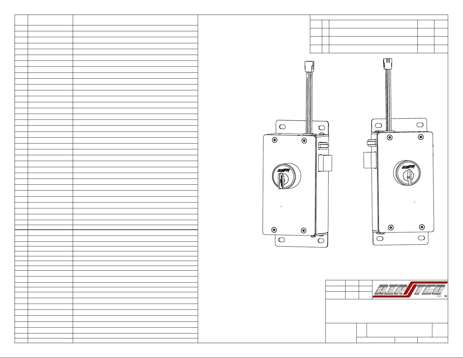
9900 Series Lock LH
NOTES:
1. 146-9900-126L may be substituted for 146-9900-125L in left
hand motor locks
2. 146-9900-126R may be substitued for 146-9900-125R in
right hand motor locks
3. Same length button head cap screws may be used in place
of hex head cap screws to mount motor/solenoid assemblies to
lock body. Specifically item numbers 36 (used to mount
solenoid assemblies) and 37 (used to mount motor assemblies)
9900 Series Lock RH
ITEM
NO.
PART NUMBER
DESCRIPTION
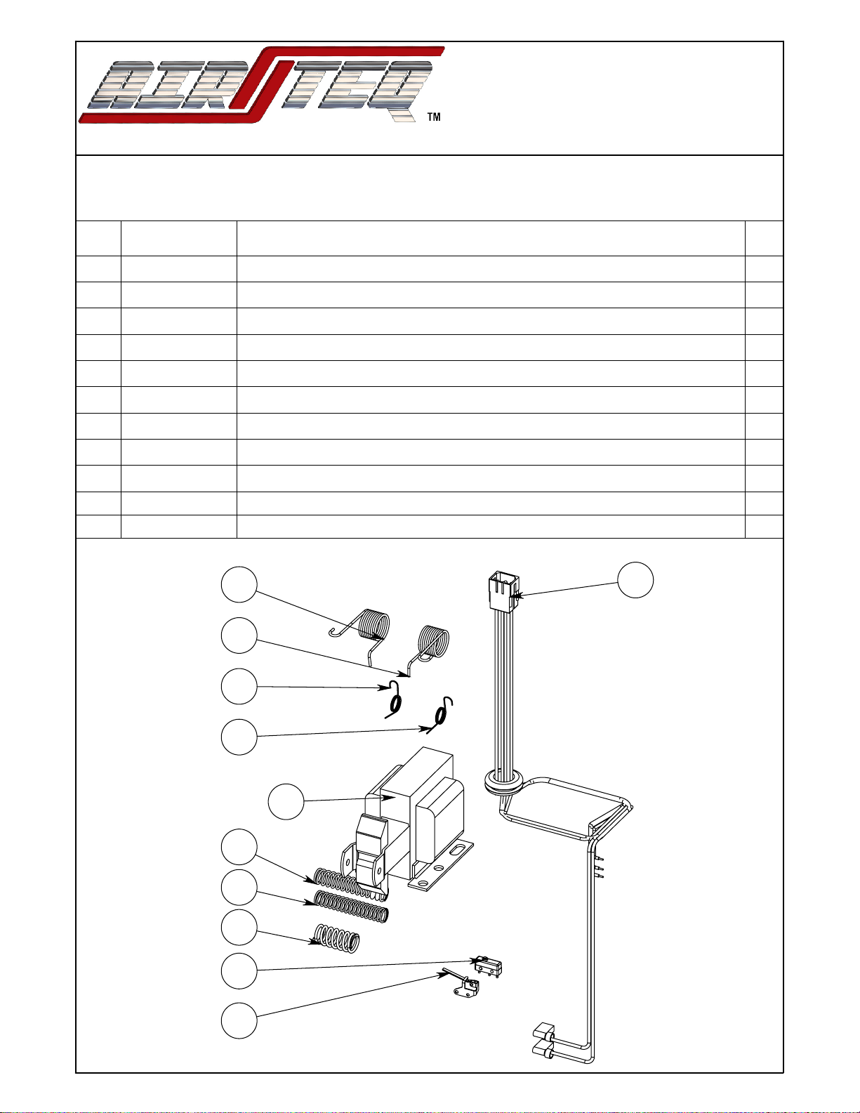
1 10002511
Shoulder Screw Ø3/8"x1 1/4", 5/16-18 Nylock
2 10002513
Shoulder Screw Ø3/8"x3/8", 5/16-18 Nylock
3 10003203
Spring Anchor, 7/8in, 8-32x5/8 Thread, Black Oxide
4 10003204
Hook End Ext. Spring, .375"OD, 2.5"Length
5
146-9900-107L
Actuator Assembly, Left Hand
6
146-9900-107R
Actuator Assembly, Right Hand
7
146-9900-107SL
Solenoid Lock Actuator Assembly, Left Hand
8
146-9900-107SR
Solenoid Lock Actuator Assembly, Right Hand
9
146-9900-122
Latchbolt Assembly
10
146-9900-124L
Left Hand Deadlatch Assembly
11
146-9900-124R
Right Hand Deadlatch Assembly
12
146-9900-125L
Deadlatch Catch Indication Assembly, LH
13
146-9900-125R
Deadlatch Catch Indication Assembly, RH
14
146-9900-126L
Deadlatch Pivot / Lock Status Switch Mount Assembly, LH
15
146-9900-126R
Deadlatch Pivot / Lock Status Switch Mount Assembly, RH
16
146-9900-272
9900 Key Switch Assembly, Keyed Two Sides
17
146-9912M-100L
9900 120VAC Left Hand Motor Assembly
*17*
146-9912M-100L-HC
Half Cycle, 9900 120VAC Left Hand Motor Assembly
18
146-9912M-100R
9900 120VAC Right Hand Motor Assembly
*18*
146-9912M-100R-HC
Half Cycle, 9900 120VAC Right Hand Motor Assembly
19
146-9912S-100
9900 120VAC Solenoid Assembly
20
146-9924M-100L
9900 24VDC Left Hand Motor Assembly
*20*
146-9924-100L-HC
Half Cycle, 9900 24VDC Left Hand Motor Assembly
21
146-9924M-100R
9900 24VDC Right Hand Motor Assembly
*21*
146-9924-100R-HC
Half Cycle, 9900 24VDC Right Hand Motor Assembly
22
150-9900-110L
Side Housing Weldment, Left Hand Lock
23
150-9900-110R
Side Housing Weldment, Right Hand Lock
24
160-9912M-100
9912M Main Wiring Harness
25
160-9912S-100
9912S Main Wiring Harness
26
160-9924-100
9924 Main Wiring Harness
27
216-1000-028
Mogul Cylinder, SPANNER Lock NUT
28
216-9900-100
Main Housing Back
29
216-9900-102
Back Mounting Plate Keyed Back Side
30
216-9900-105
Cover Plate
31
216-9900-217
Deadlatch Cushion
32
216-9900-220L
Spring Support Base, LH
33
216-9900-220R
Spring Support Base, RH
34
216-9900-255
RLB Arm
35
310-2520-001
BOLT, HEX HD, 1/4-20 X .62 LG, STL, PLATED
36
310-2520-004
BOLT, HEX, HD, 1/4-20 X .38 LG., STL, PLATED
37
310-2520-045
Screw, BHCS, 1/4-20 X 3/8, Black Oxide
38
310-3100-000
Shoulder Screw, Ø5/16"x3/8, 1/4-20x7/16
39
311-2520-082
Screw, FH,Pin TORX, 1/4-20x1/2, Stainless Steel, UC Head
40
312-3118-004
Thin "Jam" 5/16-18 Nylock nut. McMaster 94945A213 or eq.
41
313-3100-005
5/16in D Washer McMaster 96025A167 or Eq.
41
313-0000-003
WSHR, LOCK, SPLIT, 1/4, STL, PLTD
43
313-0000-120
Fender Washer
44
315-9900-001
Spring, .485"OD x 2.25" Length
45
315-9900-002
Spring, .405"OD x 2.25" Length
46
315-9900-005
.60"ODx1.25"length
47
315-9900-010
RLB Catch, Left Hand Torsion Spring
48
315-9900-011
RLB Catch, Right Hand Torsion Spring
49
315-9900-021
Actuator 360° Right Hand Torsion Spring
50
315-9900-022
Actuator 360° Left Hand Torsion Spring
51
340-0000-170
Anchor Mount Cable Tie Holder
52
340-0000-204
Cable Tie, 4in
REVISIONS
C
B
1/25/18
Added Half Cycle Part Numbers, 216-9900-205 Now Part
of Motor Assemblies
10/27/15
Cumulative: Hex Head motor/sol. mounting screws, add 313-0000-
120, add 216-9900-217 for Sol. locks, etc.
11/17/14
Initial Release
C
ECN #
11/17/14
RLP
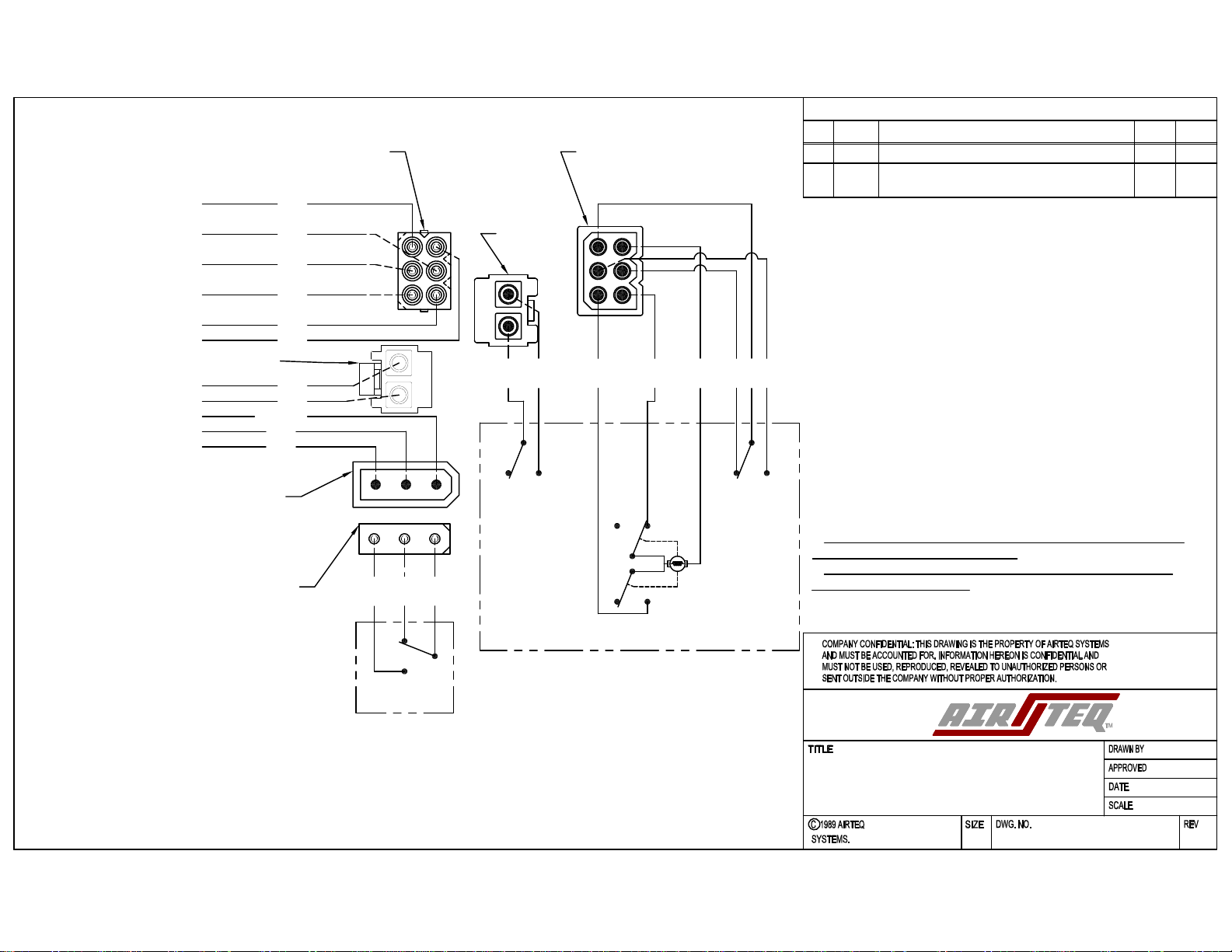
9900 Series 120VAC/24VDC Motor
& 120VAC Solenoid Lock
9912M / 9924M / 9912S
APPROV.
DATE
DESCRIPTION
REV.
SCALE: 1:4
SHEET 1 OF 7
REV
DWG. NO.
A
SIZE
TITLE:
NAME
DATE
CHECKED
DRAWN
FINISH:
A