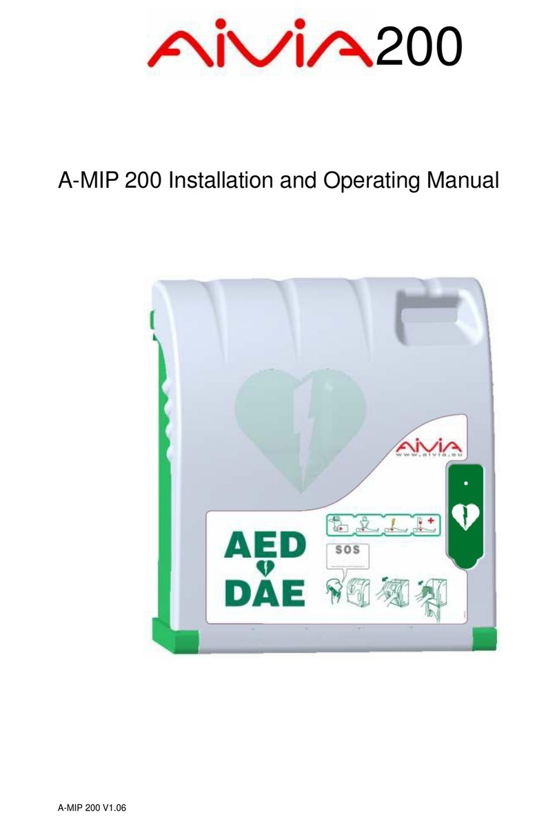
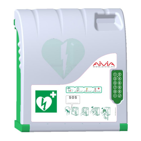
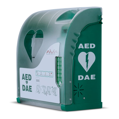
Aivia A-MIP 200 User manual

200
A-MIP 200 Installation and user guide

2
General Information
Environmental information
• When returning the AIVIA, you should only use the
original packaging.
• Do not dispose of the AIVIA or its packaging with nor-
mal household waste. Use the collection system in place
in your area. The use of collection systems will help pre-
serve the environment and your health.
•The AIVIA can contain batteries in compliance with EU
Directives 2006/66/CE and 2008/103/CE. These cannot
be disposed of with normal household waste. Please use
the system for collecting used batteries in place in your
area. The proper disposal of used batteries preserves
the environment and your health.
Warranty
Do not disassemble the various elements that constitute
the AIVIA.
Do not insert any objects into any openings.
Only qualified personnel may carry out repairs on the
AIVIA.
Failure to comply with this will void any warranty.
Any operation or assembly procedures expressly
prohibited or not recommended by this manual, will also
void the warranty.
Maintenance
CAUTION
THE AIVIA CONTAINS BATTERIES.
THERE IS A RISK OF EXPLOSION IF THE
BATTERIES SUPPLIED FOR USE BY THE AIVIA ARE
REPLACED BY INCORRECT BATTERIES.
ONLY AN AUTHORIZED OPERATOR CAN CARRY
OUT MAINTENANCE OPERATIONS, INCLUDING
REPLACING THE BATTERIES.
Safety
• To avoid risk of fire or electric shock, the AIVIA should
not be exposed to any naked flame.
• Leave a space of at least 13 cm around the AIVIA to
assure proper ventilation.
• Keep the AIVIA away from radiators or any other heat
source. Do not place the AIVIA near any devices that
generate heat. Do not place anything under the AIVIA.
• To avoid damage, do not insert objects into any of the
openings in the AIVIA.
• Never install the AIVIA in direct exposure to sunlight.
• Do not expose the AIVIA to any moisture when the
door is open.
Important
Read this manual before installation and use of the
Aivia. Read this section carefully and follow the
instructions.
The warranty does not cover damage caused by failure
to follow these instructions.
AIVIA PROTECTION are wall mounted protection units
that serve to house and shelter AEDs. The AIVIA
PROTECTION does not ensure control of the AED, it is
the sole responsibility of the DISTRIBUTOR to inform
their own SUB-DISTRIBUTORS and USERS of their
obligation to verify the presence and operating status of
the AED by carrying out regular on site checkups.
Depending on the options chosen, the AIVIA
PROTECTION can trigger a visual and sound alarm.
The alarm is intended as a warning signal in case of any
malfunction, but no data log of malfunctions is recorded.
In no event can the presence and operating status of
AEDs in an AIVIA PROTECTION be controlled from a
distance. The AIVIA should in no case be a substitute for
the checks and inspections recommended by the
manufacturer of the defibrillator.
Installation must be carried out by a qualified operator or
authorized by the Aivia’s manufacturer
Never install an AIVIA in direct exposure to sunlight.
The unheated AIVIA must be installed in a temperate
environment, in accordance with the manufacturer’s
specifications for the defibrillator.
The heated AIVIA must be installed in an environment
that respects the operating temperatures of the AIVIA.
You must monitor and follow up alerts related to
temperature.
The characteristics of the AIVIA are subject to changes
without notice.
The manufacturer of the AIVIA reserves the right to
change products at any time, including unlimited
modifications to previously delivered products.
The AIVIA brand is a registered trademark.
• The fixations must be adapted to the type of surface on
which the AIVIA is fixed.
• The manufacturer cannot be held liable for improper
installation or in the case of accident or injury during its
installation.

3
Installation 4
Important 4
Aivia presentation 4
Identification Label 4
Initial opening 4
Aivia installation 5
Connect power to the Aivia 6
Setting up the defibrillator 7
Installing seals 7
Pictograms 7
Contents
Use 9
Night mode operation 9
Heating option operation 9
Alarm operation 9
Using the Aivia 9
After using the defibrillator 9
Aivia Maintenance 9
In case of malfunction 10
Aivia 200 W 12
Electrical Installation 13
Specifications 14
Mechanical properties 14
Technical properties 14
Compliance 14

4
Installation
Identification Label
• The identification label is located inside the Aivia.
• In the event you need to reach customer services or
your distributor, please make sure you have your Aivia
reference and serial number available.
Initial opening
• To open the Aivia door before wall mounting, use a
small screwdriver.
• Slide the screwdriver between the door and the Aivia
frame.
• Lift up the screwdriver, taking care not to mark the
components.
. Do this on both sides of the Aivia.
Serial Number
Reference Options
Aivia presentation
1Electronic compartment.
2Light sensor.
3Seals support
4Heating film *.
5Night and alert indicators.
6Door
7Identification plate. * Option
1
2
4
3
6
5
7
9
8
8Fixation holes.
9AED holding sandow .
Important
Read this manual carefully before setting up and using
the Aivia.
Never install an Aivia in direct exposure to sunlight.
You risk exposing the defibrillator to excessive
temperatures.

5
Installation
Aivia Installation
Never install an Aivia in direct exposure to sunlight.
You risk exposing the defibrillator to excessive
temperatures.
• Installation must be carried out by a qualified operator
who adheres to the Bornavie charter or authorized by
the Aivia manufacturer
• If the Aivia is installed in a public street or place with
public access, install a fixed ground plate (abutment) or
column.
• Fixations must be suitable for the type of surface which
the Aivia is attached to.
• Aivia working zone must be kept free as specified
above.
• The exact dimensions of the Aivia are provided at the
end of this document in the Specifications section.
• Make sure that every cable has been taken through the
cable passage before affixing the Aivia to the wall.
• Let a free space of 140 cm (55,11 in) in front of the
supporting wall to allow for easy opening of the Aivia.
• To mark fixations and cable passageway, use the
drilling template provided with the packaging.
• Put the template against the wall, with the arrow facing
upwards and towards you.
Fixation holes
24VDC Cables
passage
Useful zone for Aivia working zone
215 mm
190 mm220 mm 220 mm
150 mm
1300 mm
8,5 mm
0,33 in
8,66 in 8,66 in7,48 in
5,90 in
8,46 in
51,18 in
1400 mm
Useful zone for Aivia implantation
55,11 in

6
Installation
• Use suitable mounting method for the type of substrate
on which Aivia is installed.
• Mounting must be able to support a minimum load of
20 Kg.(44lb).
• Fixing example:
• Washer plus screw head thickness must not exceed 8
mm. (0,31 in)
Affix the Aivia using the 3 fixation holes
Connect power to the Aivia
The Aivia must be supplied with 24VDC power,
ensure compliance with the "Electrical Installation"
section
• Unscrew the fixing screw with a phillips screwdriver
and pull out the hatch from the top.
• Pass power wiring through the wiring pass through
• Connect cables to the supply terminals, respecting
proper polarity.
• Connect the terminal to the power connector.
• Ensure that the Aivia is under power by checking that
the red warning lights are blinking.
• Replace the access door by insert the lower edge
first.
•Insert mounting screws using a Philips screwdriver.
12
3
4
1Supporting wall.
2Pin/Nylon plug.
3Fixing screw, M6 minimum, M8 maximum.
4Shim 14mm (0,55 in) maximum.
1
2
1
2
2
1
2
1
1
Access door mounting screws.
Electronics access door
1 Power connection
1+24V DC Red cable.
20V Black cable.
1Cable passage
2Power supply cables

7
Installation
Installing seals
• The Aivia is shipped with two seal kits
• Seals give evidence of door having been opened
• Regularly inspect seal condition
• You must install the AED status sensor on the
AIVIA W before establishing the seals. Please refer
to the AIVIA 200 W section
Seal installation
• Completely close the Aivia door. Be sure to pull the
door base toward you before shutting the door
• The surfaces must be clean, dry and without any
grease
Setting up the defibrillator
Pull on the holding strap and insert the AED behind the
strap
• The strap allows for a simple extraction of the AED
while ensuring the AED is securely held.
2
1
Pictograms
• The signs on the door of AIVIA inform you of what to
do in an emergency.
• You must mark the emergency number to call in the
SOS pictogram if one is not already noted there.
• Remove the protective film from the seal
• Stick the seal covering both the AIVIA door and
chassis
• Seals must be installed on both sides of the AIVIA
1- AED to be inserted vertically.
2- AED holding strap
.

8
Notes

9
Use
Night mode operation
• The Aivia is equipped with a light detector. In low
ambient light, blinking white lights help identify the
location of the Aivia.
• Take the defibrillator out
• Go to the victim
• Switch on the defibrillator
• Follow the defibrillator instructions
Heating option operation
• The heating option allows to maintain the AED
operating temperature within working temperatures. In
extreme cold temperatures, it is worthwhile checking that
the alert temperature is not signaled by the flashing of
the red indicators.
• The fan allows the heat to be extracted from the Aivia.
In hot weather, it is worthwhile checking that the alert
temperature is not signaled by the flashing of the red
indicators
Using the Aivia
If you are a witness of an incident requiring use of a
defibrillator.
Call emergency services.
Speak in a strong, clear voice, describe the situation
and specify the location of the incident.
Open the Aivia door by pulling the top.
The visual warning will be given by blinking red lights.
If your Aivia is equipped with an audible alarm, it will
sound for about 3 minutes (30 seconds for an AIVIA W).
Aivia Maintenance
• Clean the surfaces of the Aivia using a soft damp
cloth. Wipe the Aivia with a soft, clean and dry cloth. Do
not use chemical products or cleaners, which may
damage the Aivia.
• Do not rub the Aivia with a hard object, which may
scratch or permanently damage the surfaces.
• Do not use any high pressure cleaner.
• Regularly inspect seals conditions
• If the Aivia seals have been broken, make sure that all
items of the defibrillator are present and working
properly.
In case of any doubt, contact your defibrillator distributor.
Alarm operation
Door opening alarm:
• When the door is opened the visual alert is given by
the flashing of the red indicators.
•If your Aivia is equipped with an audible alarm
(Reference: X2A200-XX100 or X2A200-XX101) it will
sound for 3 minutes (30 seconds for an AIVIA W).
•Close the door to stop the alarm.
Temperature alarm:
•The temperature alarm, indicated by a continuously
flashing red light when the door is closed, is
triggered below 5º or above 40º.
After using the defibrillator
• Do not place the defibrillator back inside the AIVIA
before reactivating it.
• Follow the instructions in the defibrillator’s manual to
reset it for use.
• The manufacturer may be able to help reactivate the
defibrillator. Please feel free to contact them.
• After reactivating the defibrillator, replace it inside the
AIVIA using the instructions in the section "Setting up
the defibrillator."
• Replace the seal using the instructions in the section
"Installing seals".

10
In case of malfunction
•When power is applied red lights do not blink.
1. Check wiring polarity.
2. Check power supply connection.
3. Check voltage (24VDC) at the terminals.
4. Check proper insertion into terminals
5. Contact distributor.
•White lights do not blink in night operation.
1. Check the AIVIA power supply.
2. Contact your distributor.
•Red lights do not blink when the door is being opened.
1. Check the AIVIA power supply.
2. Contact your distributor..
•Siren does not works when the door is opened.
1. Check the Siren option on the identification plate
2. Check the AIVIA power supply.
3. Contact your distributor.
•Red lights flash (Aivia 200 W).
Number of flashes Cause Solution
2Faulty memory Contact your distributor
3Lost setting Re-parameterize the Aivia
4Temperature senso problem Contact your distributor
5Temperature alarm Check defibrillator function. If necessary, contact your
distributor
6Absence AED Check the presence of AED and attach the sensor AED
to its base
7AED out of order Check defibrillator function

11
Notes

12
Aivia 200 W
Aivia 200 W
The Aivia 200 W permits to verify and trace the AED
monitoring information of the AIVIAnet server.
• Maintenance operations.
All maintenance operations must be performed after
pressing the maintenance button.
Maintenance mode stops the siren and the red warning
lights. It blocks the data transmission at the AIVIAnet
server.
A maintenance operation without activating the
maintenance mode may result an additional cost of the
subscription.
• Installation of the AED status sensor
The AED Status sensor requires that the AED and its
status indicator be operational in order to correctly check
the operational status of the indicator. Please check your
AED instructions if needed..
• The AED status sensor connects to the base and then
comes to rest on the base it self attached to the AED.
• For the installation of the adhesive base on the AED
and the calibration procedure of the sensor, please refer
to document.
1
1Maintenance button
1RJ12 for AED Status Sensor
2RJ12 from the AED Status Sensor
1
2
• Connection to the AIVIANET server.
After powering up, the connection to the AIVIANET
server is automatic.
Visit the supervision website : monitoring.aivia.eu for
more information sent by your Aivia.
On the supervision website, you can download the
manual of the AIVIANET A-GUS in the documentation
section.
• Battery of the Aivia 200 W.
The Aivia is equipped with a battery enabling it, in the
event of a power failure, to continue to monitor the AED
and to transmit the information to the server AIVIANet.
This battery provides autonomy to the Aivia 200 W over
3 days.
In this mode, the white and red leds and siren do not
work.
• Stop of the Aivia 200 W.
To stop the Aivia, open the door and press the
maintenance button for 5 seconds.

13
Electrical installation
Power Supply Unit
Must be located outside the Aivia, never installed
inside the Aivia.
•The power supply block must include:
• A 10A/30mA residual current device, serving both
to protect and disconnect the hardware.
• A SELV or equivalent 24VDC +-2% / 3A Class 2,
with limited power output, and IEC 60950-1 conform.
• The cable connecting the residual current device
and the power supply must be a section of 1,5 mm²
•The main connection must include the primary phase,
neutral, and earth.
•The maximum full load secondary voltage drop must
not exceed 2%, or 23.5V at the Aivia terminal.
•The power block must be dust and water proof, and
ventilated**.
•Wires must be held against themselves by a collar
at the nearest of the holding terminals. The power
block wiring must conform to standards in force in
the country of use.
* Recommended power supply: PYRESCOM C_AL/HDR100-24CA.
** Natural or forced convection depending on the environnment and
thermal characteristics at maximum load.
SELV Wiring:
• Type U1000R2V. 2 insulated jacketed conductors, 1.5
mm² area, 10 metres maximum length.
• Use red or maroon colour cable for the +24V line.
• Use black or gray colour cable for the 0V line.

14
Specifications
Mechanical properties
• Weight
X2A200-XX000: 5.95 Ib
X2A200-XX100 (siren option): 6.61 Ib
X2A200-XX001 (heating option): 6.39 Ib
X2A200-XX101 (heating & siren option): 7.05 Ib
•Materials:
Door: Polycarbonate.
Frame: ABS.
Bracket: ABS.
Hatch : ABS.
Technical properties
• Power supply:
24 VDC +-2% / 3A, TBTS source to limited power,
complies with IEC 60950-1.
.
•Electrical consumption:
• X2A200-XX000:
Minimum: 0.9 mA.
Maximum: 80 mA.
• X2A200-XX100 (siren option):
Minimum: 0.9 mA.
Maximum: 500 mA.
Sound level: 103 dB / 39 inchs (1 metre).
•X2A200-XX001 (heating option):
Minimum: 0.9 mA.
Maximum: 2000 mA.
•X2A200-XX101 (heating & siren option):
Minimum: 0.9 mA.
Maximum: 2400 mA.
Sound level: 103 dB /39 inchs (1 metre).
• Operating temperatures and humidity:
Minimum: -4°F (-20°C)
Maximum: 131°F (55°C)
Relative humidity: 95% without condensation.
• Temperature alarms:
Low temperature alarm: 41°F (5°C)
High temperature alarm: 104°F (40°C)
• Heating option:
(References: X2A200-XX001 or X2A200-XX101)
Heating setpoint: 55°F (13°C)
Ventilation setpoint: 81°F (27°C)
• Maximum weight capacity: 11 lb (5 kg)
• Maximum altitude: 78740 inchs (2000 m)
Compliance
IEC 60950-1:2005+A1:2009
EN 60950-1:2006 (Second Edition) +A11:2009
+A1:2010 +A12:2011
UL 60950-1:2007 R12.11
CAN/CSA-C22.2 No.60950-1-07+A1:2011
EN 61000-6-2:2005+A1:2006
EN 61000-6-3:2007+A1:2011
FCC Part 15:2009
ICES 003:2004

15
Notes
Other manuals for A-MIP 200
1
Table of contents
Other Aivia Medical Equipment manuals
Popular Medical Equipment manuals by other brands

Maquet
Maquet CS100i Operator's guide

Medela
Medela Supplemental Nursing System Instructions for use

Haemonetics
Haemonetics Cell Saver 5+ Operator's manual

Bodypoint
Bodypoint Moduform Dynamic Arm Support AS001 manual

EMS
EMS Swiss LithoCast Trilogy FT-231 Instructions for use

GIBAUD
GIBAUD MALLEOGIB Instructions for use