DESCRIPTIONREF.NO. KANRI
NO.
PARTNO. KANRI
NO.
REF.NO. DESCRIPTIONPARTNO.
ELECTRICAL MAIN PARTS LIST
IC
87-002-677-080 C-IC,TA2002F
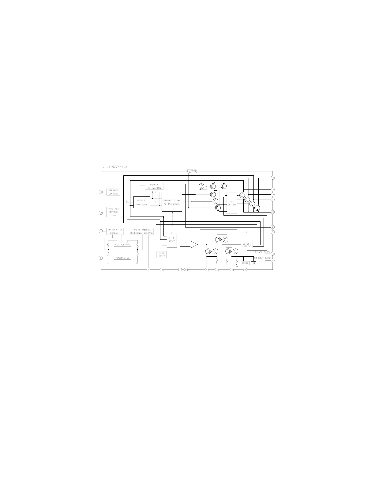
87-A20-532-140 C-IC,LB1977M-TLM
87-A21-567-040 C-IC,TMP47C443LDM-1B45(EL)
87-A21-566-040 C-IC,S-80820ANNP
87-A21-565-040 C-IC,S-80817ANNP
TRANSISTOR
89-327-125-080 C-TR,2SC2712GR
89-113-625-080 C-TR,2SA1362GR
87-026-581-080 C-TR,RN2405
87-A30-085-040 C-TR,CSA1362GR
87-026-267-080 C-TR,RN2407
DIODE
87-A40-822-040 C-DIODE,CRS01
MAIN C.B
C101 87-012-275-080 C-CAP,U 1200P-50 B
C102 87-012-275-080 C-CAP,U 1200P-50 B
C103 87-012-275-080 C-CAP,U 1200P-50 B
C104 87-012-275-080 C-CAP,U 1200P-50 B
C105 87-012-276-080 C-CAP,U 1500P-50
C106 87-012-276-080 C-CAP,U 1500P-50
C107 87-010-501-010 CAP,E 47-4V
C108 87-010-501-010 CAP,E 47-4V
C111 87-015-688-010 CAP,E 4.7-35
C112 87-012-142-080 CAP, S 0.33-16
C113 87-010-805-080 CAP, S 1-16
C114 87-012-141-080 C-CAP,S 0.22-16 Z F C2012
C117 87-012-278-080 C-CAP,U 2200P-50 B
C118 87-012-278-080 C-CAP,U 2200P-50 B
C119 87-A10-263-080 C-CAP,U 0.1-16 Z F
C120 87-A10-263-080 C-CAP,U 0.1-16 Z F
C121 87-010-502-010 CAP,E 100-4 M KS
C122 87-010-503-010 CAP,E 220-4 GAS
C125 87-010-501-010 CAP,E 47-4V
C127 87-010-805-080 C-CAP,S 1-16
C128 87-010-805-080 C-CAP,S 1-16
C303 87-010-196-080 C-CAP,S 0.1-25
C304 87-010-196-080 C-CAP,S 0.1-25
C401 87-A10-201-080 C-CAP,S 0.33-16 KB
C403 87-010-805-080 C-CAP,U 1-16 Z F
C404 87-016-526-080 C-CAP,S 0.47-16 K B
C405 87-010-992-080 C-CAP,S 0.047-25 B
C406 87-A10-263-080 C-CAP,U 0.1-16 Z F
C407 87-010-992-080 C-CAP,S 0.047-25 B
C408 87-010-992-080 C-CAP,S 0.047-25 B
C409 87-010-992-080 C-CAP,S 0.047-25 B
C410 87-A10-263-080 C-CAP,U 0.1-16ZF
C701 87-A10-263-080 C-CAP,U 0.1-16 Z F
C702 87-012-141-080 C-CAP,S 0.22-16 Z F
C705 87-A10-263-080 C-CAP,U 0.1-16 Z F
C706 87-010-805-080 CAP, S 1-16
C707 87-010-196-080 C-CAP,S 0.1-25
C708 87-A10-263-080 C-CAP,U 0.1-16 Z F
C710 87-A10-263-080 C-CAP,U 0.1-16 Z F
C714 87-A10-263-080 C-CAP,U 0.1-16 Z F
C801 87-A10-489-010 CAP,E 220-4 7L SR
D601 87-A91-355-040 C-LED,BR1112H-TR-RED
J101 87-A60-438-010 JACK,3.5 BLK ST W/O SW (1537)
J801 87-A61-124-010 JACK,DC DIA2.75 BLK TC
PS501 87-A90-440-010 SNSR,PHOTO GP2S24N2-B
R713 87-022-245-080 C-RES U 18K-1/16W F
R727 87-A10-263-080 C-CAP,U 0.1-16 Z F
S101 87-A90-050-010 SW, SL 2-2-2 NS (BLK)
S301 87-A90-050-010 SW, SL 2-2-2 NS (BLK)
S701 87-A90-665-280 C-SW,TACT LS7A2M
S702 87-A90-665-280 C-SW,TACT LS7A2M
S703 87-A90-665-280 C-SW,TACT LS7A2M
S704 87-A90-665-280 C-SW,TACT LS7A2M
S705 87-036-379-180 C-SW,SL1-1-2 SS350
S706 87-A91-365-080 C-SW,PUSH 1-1-1 SPVG21
SFR401 87-A91-653-040 C-SFR,K 33K H RH03AEC
TH401 87-A91-675-080 C-THMS,NTH5G16P39B472K 07TH
VR101 87-A91-650-010 VR,RTRY 50KCX2 H XV0102G
X701 87-A70-241-010 VIB,CER 4.000MHZ CSTS0400MG03
88
A
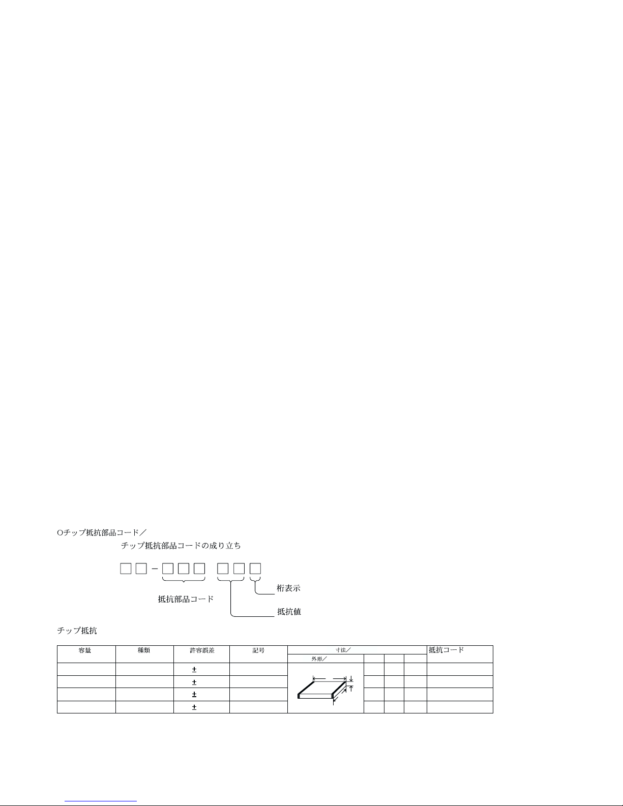
Resistor Code
Chip Resistor Part Coding
Figure
Value of resistor
Chip resistor
Wattage Type Tolerance
1/16W
1/10W
1/8W
1608
2125
3216
5%
5%
5%
CJ
CJ
CJ
Form LW t
1.6 0.8 0.45
2 1.25 0.45
3.2 1.6
108
118
128
: A
: A
CHIP RESISTOR PART CODE
0.55
Resistor Code
Dimensions (mm)
Symbol
1/16W 1005 5% CJ 1.0 0.5 0.35 104
Lt
W
- 3 -