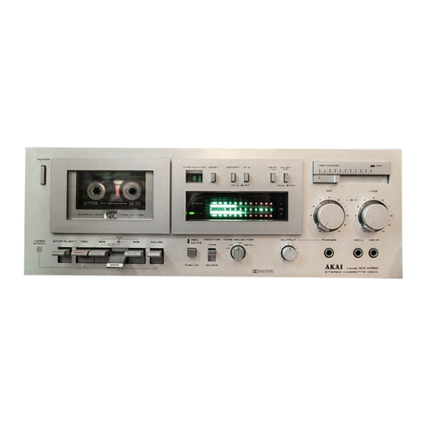
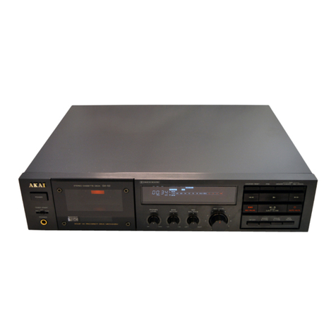
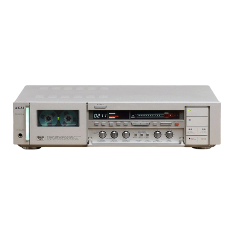
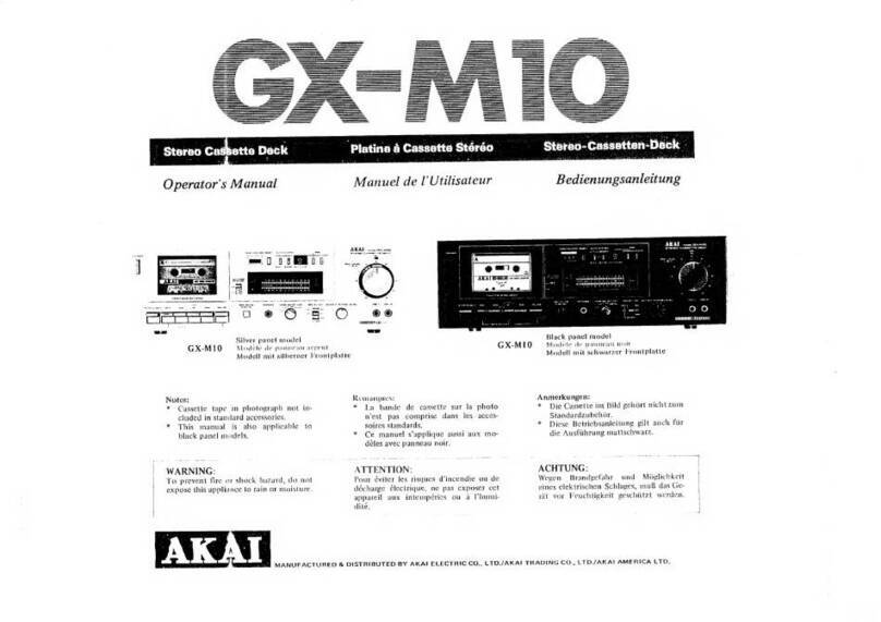
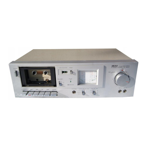
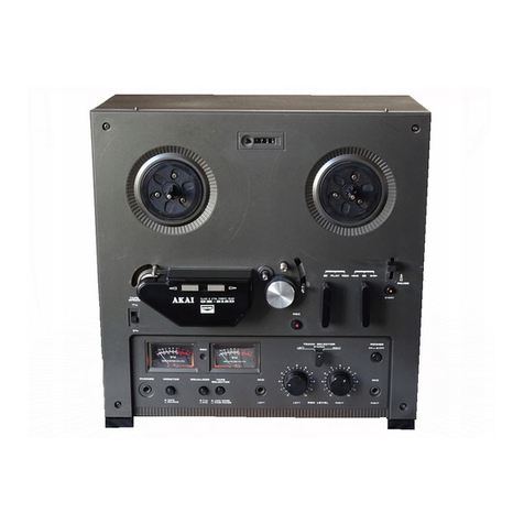
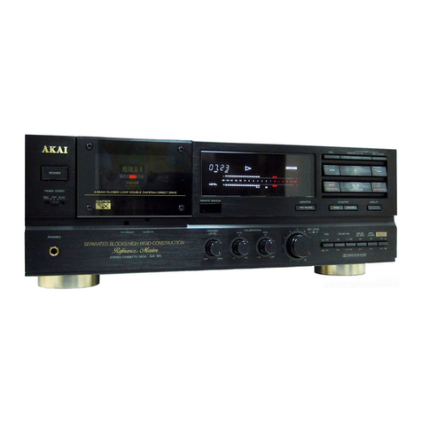
Akai M8 User manual


MODEL
NUMBER
:
WEIGHT
(NET
IN
CARTON):
DIMENSIONS
POWER
REQUIREMENTS
:
POWER
CONSUMPTION
:
‘RECORDING
SYSTEM
:
PLAYBACK
SYSTEM
:
TAPE
SFEED
TAPE
SPEED
DEVIATION
:
WOW
AND
FLUTTER
:
FAST
FORW..RD
AND
REWIND
TIME:
FREQUENCY
RESPONSE
:
DISTORTION
SIGNAL-TO-
NOISE
RATIO:
CROSS
TALK
|
SPECIFICATICNS
ere
errr
en
TS
Akai
Model
M-8,
portable
4-track
stereo
tape
recorder.
47.3
lbs.
2.4
Ibs.
supplied.
20°H
-:13’W
49’D,
overall,
case
clo-
sed.
(510H
340W
x
226D
in
m/m)
{21.5
kg.)
for
M-S
il.l
kg.)
for
ell
accessories
A.C.
100,
110,
129,
200,
220,
or
240
volts
interchangeable.
50-60
cycles.
100
VA.
Specific
“cross-field”
recording
based
on
the
theory
of
trailless
recording
bias
system.
Inline
4
track
stereo
and
4-track
monaural
recording.
Inline
4-track
stereo,
monaural
play-
back.
Three
speeds;
7'4”
(19cm.),
3-34”
(9.50em.)
and
1-%*
(4.75cm.)
per
second,
115”
second
with
an
acces-
sory
capstan
and
pinch
wheel.
Less
than
+3
per
cent
at
all
tape
speeds.
Less
than
0.15%
at
7-%
ips.
R.MS.
Less
than
0.2570
at
3-%
ips.
R.M.S.
Less
than
9.35%
at
1-
ips.
RMS.
SO
seconds
for
1,200
ft.
tape
at
50
cycles
and
75
seconds
at
60
cycles.
30
to
25.000
cps.
at
7-'%
ips;
£3
db.
40
to
21,000
cps.
2+3db.40
to
18,000
cps.
+4db.40
to
10,000
cps.
Within
2%.
at
1,000
cps,
hermonic:
at
7-4
ips;
at
3-34
ips
;
at
1-%
ips.
OVU
«total
40
db
below
recorded
level
signal
at
all
speeds.
Within
53
db
beiween
each
track.
CHANNEL
SEPARATION
:
POWER
INPUT
LEVELS
:
POWER
OUTPUT:
INSULATION
RESISTANCE:
INSULATION
YIELD
STRENGTH
:
MONITORING
yvorpiur.
SYSTEM
:
MOTOR
HEADS
MICROPHONE
USED:
SPEAKER
INCLUDED:
TUBES
USED
REELS
USED
RECORDING
LEVEL
INDICATOR:
a
TO
er
pe
rary
snaeminsetiee
a
a
EY
A
He
meme
ee:
Better
than
80
db
at
1,000
cps-i
3
VU.
Microphone
input
level
-55
db
(VR.
max}
at
1,000
cps.
Phono
and
radio
input
level
-15
db
(VR.
max)
at
1,000
cps.
Head
output,
1
mv.
at
1,000
cps.
Pre-Amplifier
output,
0.6
V
at
1,000
cps,
impedance
10,000
ohms
Main
outrnnt,
34
dbm.
up
(in
600
ohms).
fy
More
than
10
MEG
ohms
More
than
one
minute
at
A.C.
1,000
¥
with
Headphone
With
headphone
(8
ohms)
during
recordin:
Hysteresis
two-speed
motor,
dynamically
talanced.
1/100
HP.
Power
ratio,
70
per
ceni..
3,000
to
1,500
r.p.m.
at
SO
cps,
synchronous,
~
3600
to
1,800
r.p.m.
at
6C
cps.
Inline
four-track
stereo/monaural
re-
cord-play
head;
leadannn
SOND
shes
2t
1
000-
sm
PCGGHOS...
Guy
Sais
at
apy
&
Four-track,
cross-field
bias
head;
Impedance...14,000
ohms
at
60
ke.
Four-track
erase
head
Impedance...18.
000
ohms
at
60
ke.
Square-shaped,
dynainic
microphone
~
Impedance...56,000
chms
Sensitivity...
—55
db.
Frequency
Response...70
to
15,000
cps
=10db.
Two
4-inch
dynamic
speakers
for
vertical
stereo
sound
eifect
Impedance...8
chms
Allowable
Input...6
waits
Frequency
Response...80
to
12,006
cps,
2-10
db.
6267
\EF8Si
+2,
12ZAD7
.12AXK7i:-.2,
6BQ5»
2,
6%4.2,
BARS
«1.
Up
to
7”
reel
Horizonial,
A-model
VU
meter

I
HOW
TO
MEASURE
DESIGNATED
VALUES
IN
SPECIFICATIONS
TAPE
SPEED
TOTAL
HARMONIC
DEVIATION:
Record
the
1,000
cps.
sine
curve
of
DISTORTION
the
tape
speed
at
rating
speeds
with
FACTOR:
Provide
the
input
terminal
of
the
a
standard
sound
recorder
(AMPEX
351A,
for
instance)
which
is
little
af-
fected
by
the
tape
speed
deviation
throughout
the
whole
length
of
the
tape.
Put
this
standard
tape
on
the
tape
recorder
under
test
for
playing
back,
and
measure
its
output
by
a
counter,
then
convert
the
value
into
rating
power
frequency
to
evaluate
the
tape
speed
deviation.
For
a
rough
measurement,
the
tape
speed
deviation
can
also
be
measured
with
a
speed
test
timing
tape
by
the
count
on
a
stop
watch.
lested
recorder
with
1,000
cps.
sine
curve
signals
and
record
these
signals
on
a
recording
tape
at
the
zero
level
on
the
recorder‘s
internal
VU
meter.
Then
playback
the
signals
under
the
normal
recording
condition
to
meas-
ure
the
distortion
factor
by
an
oscil-
lator.
Remove
the
recording
tape
from
the
recorder,
then
read
the
noise
level
on
tne
oscillator
to
get
the
required
distortion
factor
by
the
following
formula:
dO=d—dli—d2
dO...required
d...overall
distortion
factor
dl...noise
levei
d2...distortion
factor
of
the
oscilla-
tor
used
NOISE:
Playback
the
sine
curve,
250
cps.
that
guarantees
wow
and
flutter
wiih-
tape.
recorded
on
a
glanclard
record-
in
0.07
per
cent,
and
read
the
effec-
tive
value
on
wow
meter
er
on
the
tested
recorder
to
measure
Since
the
sensibility
of
wow
and
the
voltage.
flutter
frequency
below
2cps.
and
Remove
the
tape,
then
measure
the
ahove
5cps.
drops,
the
frequency
noise
level
under
the
same
condition,
over
Scps.
is
put
to
3
db/OCT
cir-
cuit,
and
the
frequency
below
2
eps.
is
put
to
6
db/OCT
circuit
for
adjust-
ment.
This
adjusted
value
is
called
OUTPUT
:
Playback
on
the
test
recorder
the
auditory
compensated
value.
Calculate
the
ratio
betw2en
the
two
in
decibel.
WOW
AND
FLUTTER:
Playback
the
3,000
cps.
standard
tape
SIGNAL
TO
1,000
cps.
sine
curve
tape
which
was
reccrded
at
the
zero
VU
level
on
a
standard
recerder.
Terminate
the
test
recorder
with
eight
ohnis.
Square
the
voltaye
reading,
then
FREQUENCY
divide
the
figure
by
eight
ohms
to
RESPONSE:
Connect
to
the
input
terminal
of
the
(OVERALL
FREQU-
test
recorder
a
sweep
frequency
of
ENCY
RESPONSE)
the
level-20
db.
Record
the
sweep
CROSS
TALK
:
Record
1,000
cps.
signal
at
+3
VU
get
the
rms.
power
output.
signal,
playback
the
tape,
terminate
the
output
with
eight
ohms.
Read
the
frequency
response
which
should
have
a
maximum
deviation
of
6
db.
te
en
the
third
track,
then
playback
this
signal
thru
a
1,000cps.
Band
Pass
Filter.
Compare
the
output
of
tracks
1
and
2
in
decibels.

TI
LOCATION
OF
CONTROLS
SOUND
MIRROR
SPEED
CHANGE
&
ON/OFF
SWITCH
TOP
(DECK)
PANEL
TAKE-UP
REEL
SPINDLE
CAPSTAN
SHAFT
PINCH
ROLLER
CAP
PINCH
ROLLER
AUTOMATIC
SHUT-OFF
LEVER
INSTANT
STOP
LEVER
START
BUTTON
RECORD,
PLAY
SWITCH
REWIND,
FAST-FORWARD
SWITCH
RECORD
SAFETY
BUTTON
AUTO
STOP,
SHUT-OFF
SWITCH
RECORD/PLAY
HEAD
PILOT
LAMD
(RECORDING
INDICATOR)
INTERNAL
SPEAKER
ON/OFF
SWITCH
POWER
SWITCH
SPEAKER
OUTPUT
JACK
(LEFT)
TONE
CONTROL
(LEFT)
EQUALIZER
SWITCH
(LEFT)
VOLUME
CONTROL
(LEFT)
VOLUME
UNIT
METER
(LEFT)
SOUND
ON
SOUND
SWITCH
STEREO
HEADPHONE
JACK
FUNCTION
SWITCH
SPEAKER
OUTPUT
JACK
(RIGHT:
VOLUME
UNIT
METER
(RIGHT)
FEED
REEL
SPINDLE
GUARD
CIRCLE
weet
CYCLE
CONVERSION
SWITCH
CAPSTAN
STORAGE
POST
RETAINING
SCREW
TRACK
SELECTOR
KNOB
TAPE
GUIDE
ROLLER
’
TAPE
CLEANER
RELEASE
BUTTON
HEAD
COVER,
MAIN
ERASE
HEAD
INDEX
(REVOLUTION)
COUNTER
RESET
BUTTON
CROSS-FIELD
HEAD
DIN
(ONE
CONNECTION)
JACK
DICE
LD
INDUT
(LEET
CHANNET)
PRE-AMP
OUTPUT
(LEFT)
LINE
INPUT
(LEFT)
MICROPHONE
INPUT
(LEFT)
PICK
UP
INPUT
(RIGHT
CHANNEL)
PRE-AMP
OUTPUT
(RIGHT)
LINE
INPUT
(RIGHT)
MICROPHONE
INPUT
(RIGHT)
VOLUME
CONTROL
(RIGHT)
EQUALIZER
SWITCH
(RIGHT)
TONE
CONTROL
(RIGHT)
CARRYING
CASE
YHGFOHOSCBHOSHSOSHOSOOQQOGHOHOOO
SEDHOGHHHHHGHHHOOHOPHSHOLOGOLHO®

V
DISASSEMBLY
TO
REMOVE
TAPE
TRANSPORT
UNIT
&
AMPLIFIERS
(1)
Loosen
the
RETAINING
SCREW
(G)
of
PINCH
|
(3)
Disconnect
all
of
the
PLUGS
marked
(P1), (P2), (P3),
ROLLER
(H)}
using
a
Phillips-headed
screw
driver
to
|
(P4),
(P6), (P7),
(P8)
and
(P10)
by
hand.
remove
the
PINCH
ROLLER
(H)
by
hand.
Remove
HEAD
WHEEL
'D)
and
DECK
CONTROL
KNOBS
(I)
&
(J)
by
loosening
their
retaining
screws.
Also
take
off
all
of
the
screws
identified
from
(A)
to
re
(K}
to
remove
DECK
PANEL
IP).
Bee
DO
NOT
REMOVE
™
ales
i
ete
ee
tae
coe
am.
{4)
Loosen
ail
of
the
screws
marked
from
(A!
to
(L).
to
remove
VENTILATOR
(VY).
Pte
miet
kage
o>
2
Semen
er
ner
a
ecco
TT
{2}
Loosen
the
screws
marked
from
(A)
ta
(D)
in
order

(5)
Lift
the
LEFT
AMPLIFIER
“(L)
from
the
carrying
case.
"Use
a
soldering
iron
to
disconnect
soldered
ends
of
speaker
cables
and
remove
these
cables.
Now
re.
move
TAPE
DECK
(M)
from
the
case.
(7)
(6)
Lift
the
R/IGHT
AMPLIFIER
(R)
from
the
carrying
case,
a
eri
neni
ae
perintnt
ns
ilt
e
Pamstny
—-5
-

Fig.
1
y
TRANSPORT
MECHANISM
Driving
of
Capstan
Figure
1.
(A)
Motor
{B)
Driving
Belt
(flat
belt)
(C)
Capstan
(D)
Flywheel
High-speed
rotation
of
Motor
(A)
is
reduced
by
Driv-
ing
Belt
(B)
and
transmitted
to
Capstan
(C),
which
is
connected
tc
Flywheel
with
ample
inertia
and
enables
rating
rotation
by
absorbing
minor
rotation
distortion
of
.
motor
itself.
(see
Fig.
1)
Capstan
Rotation
606
r.p.m.
at
7-14"
(19
m.}
per
sec,
303
r.p.m.
at
3-34”
(9.5
cm)
per
sec.
151.5
r.p.m.
at
1-%*
(4.75cm.)
per
sec.
Motor
Rotation
3,000
to
1,500
r.p.m.
at
50
cps.
.
'
3,000
to
1,800r.p.m.
at
60
cps.
Driving
of
Pinch
Roller
Put
tape
between
rotating
capstan
and
pinch
roller
and
‘push
pinch
roller
against
capstan,
this
will
transport
the
tape
at
rated
speed.
The
appropriate
pressure
of
Pinch
roller
at
this
time
is
between
1,000
to
1,150
grams
at
the
tape
speed
of
7-14”
(19cm.)
per
second.
Recording
and
Play
Back
Tum
the
RECORD,
PLAYBACK
knob
{A}
to
"PLAY"
position,
and
pinch
roller
presses
hard
against
capstan
to
move
tape
at
the
rated
speed.
Aiihe
same
time,
idier
(Bj
moves
between
Motor
Bushing
(C)
and
the
Take-Up
Reel
Spindle
{D)
te
transmit
the
motor
rotation
to
(D)
so
that
the
tape
is
moved
and
wound
on
the
take-up
reel.
The
Take-Up
Reel
Spindle
Base
is
made
up
of
two
plastic
rollers
(1
and
2)
with
a
clutch
felt
in
between.
The
Idler
is
rotating
the
plastic
roller
(2)
below.
There-
fore,
the
tape-winding
friction
is
adiusted
by
the
slipping
of
the
felt
to
enable
rated
winding
of
the
tape.
On
the
other
hand,
the
Supply
Reei
Spindle
(Hj
has
a
Brake,
roller
(E)
hung
on
the
Plastic
Roller
(4)
below
which
provides
appropriate
back
tension
by
the
clutch
felt
slipping
to
the
rotation
of
the
Pulley
(3)
above.
To
prevent
accidental
erasure,
the
Record
Interlock
Button
(F)
must
be
depressed
before
the
RECORD,
The
Safety
device
(G)
is
depressed
to
enter
the
record
mode.
(See
Figures
2
and
3)
Braked
Rotation
Slipping
Rotation
o
SOF
f
Fig.
3

Modes
of
Operation
:
(a)
STOP
(b)
FAST-FORWARD
|
(c)
REWIND
(d)
RECORDING
PLAYBACK
|
pinch
[Pake-up
iRewind
'Take-
ae
der
|
‘Supply
‘up-side
iside
Roller
twreel
(Wheel
|
Brake
|
Brake
{dler
x
|
x
x
en
x
|
x
-O}
0
|
0
|
x
Oo
ee
Res
ele
NOTES:
X-marks
indicates
“open”
and
O-marks
“engaged”
FAST-FORWARD
MECHANISM
Turn
the
FAST
FWD-REWIND
knob
{A)
to
"FAST
FWD”
position,
and
fhe
cam
(B)
under
the
knob
pushes
up
fhe
Lever
(C}.
The
Idler
(D)
moves
into
the
space
between
the
Plastic
Roller
(F)
above
the
Take-Up
Reel
Spindle
and
the
upper
part
of
the
rotating
motor
drive
bushing
tc
transmit
the
motor
rotation
to
the
take-up
reel
spindle.
At
the
same
time,
the
Brake
Band
(H)
and
Brake
Roller
(1)
come
off
ine
reel
spindle
to
free
ihe
Supply
Reel
Spindle
(G),
thereby
allowing
fast
winding
of
the
tape
onto
the
take-up
reel.
(See
Figures
4
and
5}
Free
Rotation
High-Speed
Rotation
ROG
O
Fig.
5
'
REWIND
MECHANISM
Turn
the
FAST
FWD-REWIND
knob
(A)
to
"REWIND”
position,
and
the
cam
(B)
under
the
knob
pushes
the
Lever
(C)
up.
The
Idler
(D}
moves
into
the
space
between
the
upper
part
of
the
rotating
Motor
drive
bushing
(B)
and
the
Intermediate
Pulley
(F!
to
transmit
the
high-speed
rotation
of
the
motor
through
the
intermediate
puiley
io
the
Supply
Reel
Spindle
|G).
At
the
same
tim>,
Brake
roller
(H)
and
Brake
Band
(1)
come
off
the
reel
spindle
to
free
the
take-up
reel
spindle
(J),
thereby
rewinding
the
taps
into
the
supply
reel
at
2
fast
speed.
(See
Figures
6
and
7)
High-Speed
Rotation
Free
Rotation
Fig.
7
STOP
CONTROL
Push
the
stop
lever
to
“STOP”
position,
Brake
Roller
(A),
and
Brake
Band
1B)
depress
reel
spindles
to
stop
rota-
tion
of
the
reel
spindles.
As
brake
rubber
depresses
the
plastic
rollers
under
the
reel
spindles,
no
friction
works
on
the
tane
itself.
Rewind
Idlerwheel
Take-up
Reel
Spindle
Take-up
Side
‘e
ser
fo™®
Urake
Bard
f
°
Cy
.
|
°
=
@.
Swpply
Side
pe
owint
sho
pw:
brake
Raltoolg
:
Gaite
Koller
Suyply
Reel
Soindle

Fig.
9
AUTOMATIC
STOP
MECHANISM
When
the
tape
is
threaded
on
the
pin
(B)
at
the
top
of
the
Automatic
Stop
Lever
{A)
comes
off
the
pin,
the
Auto.
matic
Stop
lever
returns
to
the
original
position
by
the
action
of
springs.
At
this
time,
the
panel
spring
(C)
below
the
Automatic
Stop
lever
slightly
pushes
down
the
projected
part
of
the
eccentric
gear
(D},
which
gears
into
the
Flyweel
Gear
(E)
to
start
rotating
and
pushing
up
the
Momentary
Stop
Lever
(G}
thst
is
connected
with
the
eccentric
gear
base
(F).
Thus,
the
eccentric
gear
maintains
the
mechanism
in
the
state
of
tentative
stop
for
“Playback”
or
“Recording”.
For
“Fast-forwa:a’,
or
“Rewind”,
the
Corkscrew
lever
'H)
works
to
push
back
the
"FAST
FWD,
REWIND”
knob
to
the
“Stop”
position
before
stopping
itself.
When
the
Automatic
Cut-Off
Switch
is
moved
to
“CUT
OFF"
position,
the
Shut-Off
lever
(J)
moves
to
the
arrow-
mark
direction
to
cut
the
power
circuit,
thereby
depres-
sing
the
attached
Micro
Switch
(K)
to
shut
off
the
current.
(See
a,
b,
c
and
d
in
Fig.
9)
SOUND
ON
SOUND
MECHANISM
By
pushing
SOUND-CN-SOUND
BUTTON
{A)
while
the
recorder
is
set
to
recording
condi-
tion,
LEVER
(D)
is
depressed
and
LEVER
(C)
is
lifted
through
LEVER
(B).
Refer
to
Fig.
10-a.
As
a
result,
LEVER
'C)
is
veieased
from
stop-
per
of
SW-l
and
SW-1
is
reset
to
play
condi-
.tion
as
LEVER
(E)
is
pulled
by
SPRING
(F).
Refer
to
Fig.
10-b.
In
this
condition,
SOUND-ON-SOUND
device
is
operative.
If,
however,
SOUND-ON-SOUND
is
not
operative,
checx
all
of
the
foregoing
LEVERS
to
see
that
SW-1
is
set
to
play
condition.

Wo
ADJUSTMENT
OF
TAPE
TRANSPORT
UNIT
1.
ADJUSTMENT
OF
PINCH
WHEEL
It
is
important
that
the
pinch
wheel
shaft
be
kept
in
complete
alignment
with
the
capstan
shaft.
A
proper
pinch
wheel
pressure
is
between
1,000
and
1,150
grams
when
the
unit
is
operated
at
the
tape
speed
of
7-1/2
ips.
Any
deviation
from
this
specification
will
result
in
wow
and
flutter.
Check
pinch
wheel
pressure
using
a
spring
scale
and,
if
necessary,
adjust
the
pinch
wheel
load
spring
to
suit.
2,
ADJUSTMENT
OF
TAKE-UP
IDLER
WEEERL
The
take-up
idler
wheel
must
be
kept
in
complete
alignment
with
the
take-up
reel
shaft.
When
the
unit
is
set
in
fast
forward
condition,
the
idler
wheel
will
contact
to
the
upper
knurled
wheel
of
the
take-up
reel
shaft
assembly,
and
it
will
contact
to
the
lower
knurled
wheel
during
record
or
play
mode.
Adjust
idler
wheel
load
spring
so
that
the
idler
wheel
pressure
is
kept
between
50
and
80
grams.
The
idler
wheel
wears
rapidly
if
the
pressure
is
excessive,
and
slinpage
occurs
in
case
the
pressure
is
smaller
than
the
specification.
(0)
Rewind
reel
salt
asey.
(6
Tate—ap
reel
shaft
aser.
ine
———omoe
Fetainer
ee
nylon
washer
ailite
wetat
a
itive
metal
re
mu
plate
3
star
shaped
TN
shsapeiog
ewe
!
ravsiner
——"
hh
ites
B
Se
ectainer
|
cr
i
if
han
sprog
_
ae
t
:
}
alley
Cee
ei¢
p<
ser
}
Ce"
‘
Fig.
ll
Recording
Tape
25meau
0.125mm
0.025mm
VOTE
VF
Yh
Wy
Bias
Head
PLEA
Ree
/
Play
Head
ae
+
Erase
Head
Ree/
Play
Head
Fig.
12
me
3.
ADJUSTMENT
OF
REWIND
IDLER
WHEEL
The
rewind
idler
wheel
must
be
kept
in
complete
align-
ment
with
the
rewind
reel
shaft.
The
amount
of
pressure
to
the
knurled
motor
bushing
should
be
maintained
about
50
grams
during
rewind
operation.
Adjust
both
the
idler
load
spring
and
rewind
roller.
4.
ADJUSTMENT
OF
INTERMEDIATE
WHEEL
The
intermediate
wheel
is
located
between
the
rewind
idler
wheel
and
the
rubber
ring
which
is
used
on
the
upper
part
of
the
supply
reel
shaft
assembly.
Wher
the
unit
is
set
in
rewind
mode,
it
will
contact
to
these
parts
simultaneously
delivering
torque
of
motor.
An
adequate
pressure
to
be
kept
is
50
grams.
Adjust
the
load
spring
of
the
intermediate
wheel
in
case
the
pressure
is
not
sufficient.
5.
ADJUSTMENT
OF
TAKE-UP
REEL
SHAFT
ASSEMBLY
A
felt
clutch
material
is
attached
to
the
bottom
side
of
the
reel
table
base
plate
so
that
recording
tape
will
not
be
siretched
during
fast
forwarding
operation
due
to
excessive
tension.
To
check
the
amount
of
friction
of
this
part,
place
onto
the
take-up
reel
table
a
5-inch
reel
with
recording
tape
wound
by
60
m/m
in
diameter,
and
gently
pull
the
end
of
tape
upward
using
a
spring
scale.
Adjust
the
conical
spring
so
that
the
amount
of
tension
at
this
part
will
be
kept
between
400
to
500
grams.
Another
felt
clutch
material
is
attached
to
the
take-up
drive
wheel.
Itis
used
to
provide
proper
slipping
opera-
tion
during
record
or
play
mode.
The
procedure
for
checking
friction
of
this
part
is
same
as
the
foregoing,
and
between
120
and
200
grams
of
friction
will
provide
the
bert
result.
Adjust
the
star-shaped
spring
immediate
below
the
take-up
drive
wheel.
When
the
unit
is
set
in
rewind
mode,
the
amount
of
friction
of
this
part
will
great:y
be
reduced
and
will
become
10
to
20
grams.
Check
to
see
if
this
is
satisfactory
and,
if
not,
readjust
the
star-shaped
spring
for
Brake,
and
spring
retairar
washes
accordingly.
(See
figure
11
(a)
at
left)
6.
ADJUSTMENT
OF
SUPPLY
REEL
SHAT
ASSEMBLY
A
felt
clutch
material
is
used
between
the
lower
side
‘of
the
reel
table
base
plate
and
the
rewind
rubber
ring
to
protect
recurding
tape
from
an
excessive
tension
while
rewinding
operation.
To
check
the
amount
of
friction.
of
this
part,
place
onto
the
supply
reel
table
a
5-inch
reel
with
recording
tape
wound
by
60m/m
in
diameter
and
gently
pull
the
end
of
tape
upward
using
a
spring
scale.
Adjust
the
conical
spring
so
that
the
amount
of
tension
be
kept
between
400
an
500
grams.
Another
felt
clutch
is
attached
to
the
rewind
drive
wheel
and
is
used
to
provide
proper
slipping
operation
during
record
or
play.
mode.
The
procedure
for
checking
friction
of
this
part
is
same
as
the
foregoing,
and
between
80
and
120
grams
of
friction
will
give
the
best
result.
‘When
the
unit
is
set
in
fast
forward
mode,
the
amount
of
friction
will
greatly
be
reduced
and
will
become
10
to
20
grams.
Check
to
see
if
this
is
proper
and,
if
not,
readjust
coil
spring
and
spring
retainer
washer
to
suit.
7,
ADJUSTMENT
OF
TAPE
HEAD
(See
figure
12
{b)
at
left)
A
vertical
azimuth
alignment
of
tape
head
is
the
only
adjustment
that
can
be
made
at
the
field
of
service.
To
align
tape
head,
play
8,000
cycles
recorced
on
an
Ampex
standard
alignment
tape.
Fotate
the
azimuth
alignment
screw
until
a
maximum
piayback
leve:
through
the
small
hole
which
is
positioned
on
the
shield
cover
of
the
tape
head
assembly.

Wo
ADJUSTMENT
OF
AMPLIFIER
1,
ADJUSTMENT
OF
RECORDING
BIAS
FREQUENCY
Recording/erasing
bias
frequency
has
been
set
at
60
KC
plus
or
minus
5
KC
before
shipment.
It
is
decided
by
inductance
of
the
oscillator
coil
(part
3
OSC
60)
and
its
resonant
capacitor
(part
%
C-22).
To
measure
recording
bias
frequency,
insert
a
10
or
100
ohm
resistor
in
series
to
the
record/play
head
and
connect
vertical
input
terminals
cf
an
oscilloscope
as
shown
in
the
Fig.
13.
Another
testing
instrament
to
be
prepared
is
an
audic
frequency
oscillator
and
its
output
should
be
connected
to
horizontal
input
terminals
of
the
oscilloscope.
Vary
frequency
being
generated
by
the
audio
frequency
osci-
lator
around
60
KC,
and
set
the
oscillator
at
the
point
where
a
lissajous
figure
appears
on
the
oscilloscope.
The
recording
bias
frequency
now
corresponds
to
the
reading
of
the
oscillator.
Check
oscillator
coil,
C-22,
C-27
and
bias
head
if
recording
bies
frequency
measured
is
not
within
60
KC
plus
or
minus
5
KC.
2.
ADJUSTMENT
OF
RECORDING
BIAS
VOLTAGE
A
proper
recording
bias
voltage
differs
on
each
head
from
130
to
230
volts
A.'c.,
and
it
is
stammed
on
the
mounting
bracket
of
tape
head
assembly.
To
measure
recording
bias
voltage,
connect
a
V.
T.
V.
M.
(Vacuum
T243
Volt
Mete:)
to
the
record/play
head
as
shown
in
the
Fig.
14.
Check
C-21,
C-27
and
bias
head
if
record-
ing
bias
voltage
does
not
meet
to
the
above-mentioned
specification
after
adjusting
C-27,
a
100
pf
variable
capacitor.
3.
ADJUSTMENT
OF
ERASING
BIAS
VOLTAGE
A
proper
erasing
bias
voltage
is
decided
automatically
as
recording
bias
voltage
is
set.
The
erasing
bias
volta-
ge,
however,
should
always
be
more
than
170
volts
A.C.
To
measure
erasing
bias
voltage,
connect
a
V.T.
V.
M.
to
the
erase
head
as
shown
in
the
Fig.
15.
Check
C-21
‘(1000
pt
mica
capacitor)
and
erase
head
if
erasing
bias
voltage
measured
is
lower
than
170
volts
A.C.
4.
ADJUSTMENT
OF
RECORDING
LEVEL
A
basic
recording
level,
usually
referred
to
as
“O
VU",
a
set
at
the
poirt
where
current
of
20
wA+10%
flows
to
the
recording
head
at
1000
cycles.
The
VU
meter
indi-
cates
0
VU
+2
VU
when
a
signal
of
55
db
+5
db
at
the
microphone
jack
or
—15
db
+5
db
at
the
line
input
jack
a
given
with
the
volume
control
set
at
its
maximum.
Adjustment
of
recording
level
can
be
accomplished
by
varying
sensitivity
of
VU
meter,
however,
it
is
not
neces-
sary
to
make
in
a
field
of
service
as
all
VU
meters
have
correctly
been
calibrated
at
factory
before
shipment.
See
Fig.
16
for
details.
NOTE:
Make
sure
to
stop
oscillation
by
disconnecting
the
oscillator
coil
$
CSC
60
at
the
points
marked
"RP"
and
"G"
prior
to
measurement
of
recording
level.
Cal
OOP
—
Osc~
tt
OSCILLOSCOPE
AUDIO
FREQUENCY
OSSRLATCR
Fig.
14
7
-
A
nrof
Ce
Fig.
15
TO
OSC-bU
4
RPH
Gs,
"
1000PF
'
RBH
JC,
}
@3)
4
VT
Fig.
16
:
Voltage(
V.
TLV.
ML)
Current
(iad)
=
--—
wa
x10

Vi
MAINTENANCE
PROCEDURES
1.
LUBRICATION
INSTRUCTION
For
maximum
service
life
and
optimum
performance,
lubricate
the parts
identified
below
after
each
500
hours
of
operation.
Use
only
light
machine
oil
of
good
quality
Motor
:
3
drops
Drive
Capstan
Shaft
2
drops
Rewind
Idler
Wheel
Bearing
and
Wind
take-up
Idler
Bearing.
1
drop
Intermediate
Idler
Bearing
1
drop
Pinch
Wheel.
Bearing
2
drops
Take-up
and
Supply
Reel
Shaft
Bearing
&
2
drops
Also
apply
a
liberal
film
of
light
machine
grease
to
each
roller
surface
of
all
levers
and
cams.
CAUTION:
DO
NOT
OVER-LUBRICATE,
AND
WIPE
OFF
EXCESS
IMMEDIATELY
USING
A
COTTON
SWAB
SCAKED
IN
ALCOHOL.
OTHERWISE,
THE
OVER-FLOWED
LUBRICANT
MAY
BE
SCATTERED
DURING
OPERATION
AND
DETERIORATION
OF
RUBBER
COMPONENT
PARTS
WILL
RESULT.
FLYWHEEL
AS"
MOTOR
Fig.
17
2.
CLEANING
TAPE
HEADS
AND
OTHER
PARTS
Wipe
surface
of
tape
heads,
guide
roller
bearing,
capstan
bushing
and
pinch
wheel
periodically
with
a
soft
cloth
soaked
in
alcohol
or
carbon-te}.

errr
nn
CL
OR
TE
TE
LIST
Cr
REPLACENE
NT
PARTS
Parts
No.
Nomenclature.
TOP
PANEL
81-001
002
003
004
005
007
012
013
Ol4a
014b
Olde
Ql4d
Ol4e
014£
014g
1
Dek
ror
DECK
FRAME
4,
2
_
wr
Screw,
Without
Head
3x17
OBS
Cover,
Rotary
shieid
26
4
82-001
002
002a
002b
002c¢
002d
002e
002
:
002g
002h
003
|
003a
003b
|
OO3e
004
;
004a
004b
004c
004d
O04e
od4f
004g
004h
004i
004)
Deck
Panel
ROO™WI
OLS
Guard
Circle,
Metal
93
63
Konb,
Track
Selector
1.9
27
Centrol
Head
Cover,
Main
1222
Head
Cover,
Sub
y
OLY
Name
Plaie
10309
Screw,
Retaining
Sub
2
Head
Cover
rose
*
Base,
Head
Cover
133
ie
Tape
Guide,
complete
12
Top
Plate,
Tepe
Guide
pa
Table,
Tape
Guide
C587
Bearing,
Tape
Guide
a3
52
Bottom
Plate,
Tape
Guide
S37;
Small
Table,
Tape
Guide
952
Tape
Cleaner,
Complete
O3<,
Screw
a
+e
Felt
O44)
Lever,
Tension
O43
Spring,
Tension
Lever
2
+3
Prop
A,
Heed
Cover
O'r
Prop
B,
Head
Cover
O45
Prop
C,
Head
Cover
O
+6
Screw,
Retaining
Track
0557
Selector
Cc..trol
Knob
+Screw
Flat
Mould
3x12
>:
+Screw
Truss
3x4
C4
+Screw
Flat
Mould
3x8
05C
Mounting
screw
0557
3
mm
Nut
foie
fam
4
mm
Nut
os7é
Vertes
VIowoGE7D
Deck
Frame
2OCD
1
OS
Head
Assembly,
Complete
05f
Erase
Head
Nse
Record/Playback
Head
©97
Bias
Head
(Cross
Field
Head)
2
Field
pase
Spring,
C
Prop,
Head
ast
DG
34
L364
Index
Counter,
Complete
264
Pulley,
Counter
CED
Belt,’
Counter
oe
4&Saraw
Semi-Cuhie
3x8
Oo7
Supply
Reel
Assembly
O¢
7
Plate,
Reel
Table
O570
Reel
Shaft,
Supply
Reel
O39
7Fi
Rubber
Ring
2339
Rewind
Puiley
DSszi
Spring
G,
Left
i
o%4
Washer
2523
Washer
Fin,
Large
OSf'p
Felt
Washer
o7E
Teke-up
Roller
O3c3
Holder,
Reel
O72
|
(Star
type
spring)
-
He
Von
paw)
Parts
No.
82-004:
C041
004m
004n
0040
Q04p
004q
004r
004s
004t
+
OO04u
00s
00S
O00Sb
Sc
005d
Q05e
OOSE
005g
!
|
00Sh
005i
00Sj
00Sk
0051
005m
005n
006h
007c
0074
007e
O008a
COE
O08
AAO
J
we
COSe
1
\
|
002a
009b
00Ec
C0Sd
OGSe
00S:
|
He
019
Nomenclature
Parts
No.
Nylon
Washer
2OO
210754
92.-010b
Washer
20
010c
Washer
o:
010d
Nylon
Washer,
Small
Metal
B.
Reel
Table
Washer
Pin
2b
Pulley,
B
23
Pulley,
C
OG
+Screw
Semi-Cubic
3x6
Screw,
Without
Head
4~7
+Screw
Flat
3x6
©2377
4
Take-up
Ree]
Assembly
Ree!
Shaft,
Take-up
Reel
24
Felt
Washer
rau
Take-up
Roller,
A
3
Spring
G,
Right
Dat
Deer
Skin
Ooqs
Take-up
Roller,
B
Ode
Holder,
Reel
+72
e)
Vi
a
a2
o
‘2
t
a
5
(Ster
type
spring)
Metal
A,
Reel
Toble
Spring,
F2
Washer
Roow
Nylon
Spring
i
Nylon
Washer
'
Set
Sleeve
i
Serew,
Without
Head
3x
-~.~990O
oYf
-ogr
WG
e
AS
Lever,
Complete
22%
2
Spring,
AS
Lever
126
Plate,
AS
Lever
oT
Spring
Doody
Plate,
Gear
}O%
Screv,
Gear
iid
Eccen'ric
gezr
iid
|
Gear,
Stopper
Ob?
Spring,
Stopper
Wee
|
Lever,
Autiomatic
switch
¢
1%
Screw,
Gear
Plate
mys
Instant
Stop
Lever,
Complete
i
|
Instant
Stam
Lever
i
1?
Spring,
Instant
Stop
Lever
7
tel
Holding,
Instant
Stop
Lever
y
ae
Holder,
Instant
Stop
Lever
,
of
4
Lever,
Shut-off
a
A
A
et
RE
SS
I
ER
Recording
Safety
button
|
{
Cam
Stcpper
Tie
a
|
Fiber,
Cam
BlOpPer”’
ae
|
ee
oe
ee
oe
ee
ay
—
=
|
Tasulator
Plats,
Cam
Stoppers
+Screw
4x5
126
|
|
Pinch
Whee!
20
O
ME
Metal
Cap,
Pinch
ae
i
|
Lever,
Finch
Whee!
Shaft,
Carn
Roiler
Cam
Roiler,
13
mm
Shait,
Pinch
Wheel
ae
i
Take-rp
Brake
Gand,
}
3°33
Complete
i
Lever,
Taxe-uo
Brake
Banu
i
a
oll
Olla
Olib
Ollc
Ol2a
012b
Q12c
012d
Ol2e
013b
Ol4a
014b
014c
014d.
01S”
“016
017a
017b
0138
019
C020a
020b
021
C22
023
024
C25a
025b
026:
027
028
029
030
031
032
033
034
0358
035
037
038
0394
39b
039¢
0496
040b
049
C-ila
041b
O4ic
041d
Odie
o4if
Nomenclature
Take-up
Brake
Band
!
39
Helder,
Take-up
Brake
Band
:
Shait,
Take-up
Brake
Band
¢
Lever
Qos
11
37
Supply
Brake
Roller,
Complete
Dowrsi
a?
Lever,
Cupply
Brake
Roller
1
|
3¢
Supply
Brake
Roller
OV
29
g++
Screw,
Brake
Roller
ial
Switch,
Automatic
Shut-oif
on
2
Plate,
Automatic
Shut-off
1
Switch
Saiety
Lever
A
a
Satety
Lever
B
Shaft,
Safety
Lever
{
2
Oeouk
ins
ir
G
4
Switch,
Speed
Change
;
7
(8
P
Slide
Switch)
Plate,
Speed
Change
Switch
14h
Idier
Wheel
B
29:3
guj>
oe
Bearing
(635-22).
290
225
¢
Cover,
Bearing
Say
+Screw
Truss
3x6
19
Idt,
MWhsal
A
Coon
oenet
Internal
eas
202039
Lever,
A
Loowisss
Shatt,
Lever
.
325439
Lever,
B
i37
Lever,
C
152
Lever,
G
Aeay
Metal,
Lever
G
1éO
Lover,
K
roi
Field
Lever,
A
162
Field
Lever,
B
i643
Yield
Lever,
D
+o
Field
Lever,
E
165
serew,
Field
Lever
E
4
66
Lever,
FA
it?
Lever,
FB
ib/¢
Lever,
A2
ibe
Prop
4,
Panei
72
Spring
Pin,
B
i
74
Hum
Bucking
Coil
i
7s
Switch,
Cycle
Change
|
7
3
(N3S-122)
Spring
Holder
T+
Cam
Roller,
A
73
Te
Washer
Pin,
Smeil
Stopper,
Lever
Gt
7B
Micro
Switch
(V-1A)
|
7%
Lever,
Belt
Change
i
Metal,
Belt
Change
,
4
iPai
me
WN
a,
Spring
Belt
Change
,
Prop,
Panel
Support
1
24
Nut
1
Sth
+Screw
4x12
Torsion
Spring
Spring,
Lever
3B
Spring,
Idler
Spring,
Pinch
Wheel
Spring,
B
Spring,
D
GW
ax
Gai
OY
SOA
CHW
|
|
|
Cam
Relier,
B
:
>
|
iat
|
|
|
|
|
-
oO

SVATCH
BLOCK
Parts
No.
Nomenclature
Parts
No.
82-041g
Spring,
D
(New
type)
1G
2
ooli
O4ln
Spring,
E
iq3
091;
042a
=+Screw
Truss
4x8
2902
9447p
~
001k
042b
4
+Scraw
Semi-Cubic
4x10
i¢,
0011
042c
+Screw
Semi-Cubic
4x8
23ScR
hit
OOlm
042d
+Screw
Semi-Cubice
4x6
1G
0Oln
042e
+Screw
Flat
3x6
ig2
0010
042
+Scraw
Semi-Cubic
3x6
O2}4
OClp
042g
+Screw
Semi-Cubic
3x5
Qao
OOlq
042h
+Screw
Semi-Cubic
3x18
2D
042i
Screw
A
Zoe
043a
4mm
Nut
2953
043b
3
mm
Nut
2
Od
85-001
0442
4mm
Ground
Lug
295
O0la
04465
3
mm
Ground
Lug
Lan
Ag
045a
Lock
Washer
4
mm
pares)
00th
045b
Lock
Washer
3
mm
ee
Ole
045a
Washer
20agn1
20¢G
001d
046b
Nylon
Washer
Lio
Ole
047
Button,
Start
it
OOlt
048
Lug
Plate,
3
P
219
001g
OOih
DRIVE
MOTOR
ae
83-001
»
Motor,
Complete
2O¢C2Q2'12R¢
001k
Odla
-+Screw
Semi-Cubic
3x15
|
Rt
coll
OOlb
Stepped
Pulley-3
aog1ai
ge
001m
COle
Balt
Holder
121
0022
001d
Motor
Pulley
1217
ae
OOle
Oil
Retainer
212
ON1q
OOlf
Motor
Holder
214
|
00lr
OOlg
Rotar
2AM’
4
§
OOls
0O0Lh
Cover,
Motor
|
OOlt
OOli
=
Statur
222
|
OOlu
GOij
Cover,
Motor
223
fof
O0lv
COlk
+Screw
Flat
Mould
4x56
0°
+3
00lw
OOlL
=
Metor
Fan
Tre
iael
001x
O0lm
Condenser
2.2
pF+0.6
uF
DAG
Q0ln
Holder,
Motor
Condenser
227
CASE
00lo
Hexagonal
Nut,
20mm
22/2
85-001
i
OOlp
Prop,
Moter
225mm
224%
Ola
“I1q
Prop,
Motor
21.5
mm
3
39
~
001b
O01:
Flete,
Motor
Condenser
2
3
j
poe
OOls
Suppe.'-r.
Cord
Sap
|
OOlt
+Screw
Sem-Cubie
daz4
afasf
ld
OOiu
+Screw
Semi-Cubic
4x10
2?
"7
Ole
OOlvy
+Screw
Flat
4x10
235
voit
OOlw
+Screw
Flat
3xS
2
3g
OSlg
O0lx
Washer
QDs
1237
OOlh
2002)
oS
2.
}
wh
FLYWHEEL
ASSESBLY
a
84-001
Flywheel,
Complete
=
32
CO1K
QCOla
‘Capsten
234
ool
COlb
Main
Metal
Cap,
B
Og
001m
OCic
Washer
Pin
QAO
2DIIS
O1n
OOtd Main
Metai
Case
Date
2
&
COle
Flywheel
243
Olo
SClf
4mm
Ball
Beering
Da
O0lp
OOlg
Plate,
Flywheel
eS
|
001q
OOlh
Washer,
65
mm
aa
s
oOlr
Capra
dewe
ohabr
QaAIAiASSe
Me
.1,2
Spem:
2QOAI3R+
Nig
bin
tiem,
2LOQ9K'N332
Nomenclature
Washer,
6mm
DoODsLIaA+e
Wing
Nut
ao
Rne
a4]
Screw,
Flywheel
Adjust
250
S
mm
Nut
235i
Prop
A,
Flywheel
2s
Prop
B,
Flywheel
2353
4
mm
Spring
Washer
2
3
Prive
Belt
235
+Screw
Flat
4x10
Switch
Block,
Comptate
Knob,
Record/Play
&
252
Rewind
Fast
Forwerd
Cam
A
DBAOODIIDWE:
Cam
B
241
Cara
Roller,
12mm
262
Switch
Table
A
263
Lever,
I
2b+t+
Fast/Forward
Rewind
Shaft
2
Rotary
Switch
‘V-123)
ME
Resistor
14
W
500]
2b?
Pin
19021068
Miate,
Casa
2b
Spring,
K
270
Cam
C
XT
Switch
Table
B
272
Prop,
Receptacle
273
UZ
Receptecle
A7+
Cam
Amp.
Switea
LVS
Prop,
Switch
2°76
Switch
Lever,
A
277
Switch
Lever,
Bl.
272
Switch
Lever,
C
X74
Switch
Lever,
52
DZS
Ball
Bearing,
81am
Bi
Screw,
Without
dead
4x5
2
Carrying
Case
2
O09
je
Handle
a
e-a
o
Catch
2335
Speaker
1
B6
4
P
Flug
o2)
Nut
a2
22
Hinges
2
2G
Reel
Holder,
&
Zag
Metel
Foot
ty
Caien,
Comparineni
Cover
Lad
5
P
Escutcheon
Qa
5S
P
Receptacis
oenes
+Screw
Truss
3x20
AGS
Rubber
Foot
(large)
DCG
Rubber
Foot
{smali
2.47
Ventilator
Panel
242
Ventilator
Panel
BQQqQ
Fuse,
2A
>»
a0
Fuse
Holder
3234
ORI”
Q
ae
Parts
No.
8-AL101
AR101
AL102
AR102
A103
Al04
A108
A106
A107
8-AK2
C4
cs
C6
C7
C8
C19
C20
C21
Nomenclature
Auop.
panel,
Left
5
ache’
Amp.
panel,
Right
so
Ls
Ventilator
bace,
Lett
3.
Ventilator
bas2,
Right
30+
Amp.
chassis
Bay
Amp.
chassis,
A
$90)
Amp.
chassis,
B
Bde:
Hum
balancer
mount
"3
ae
4P
jack
mount
355
C.R.
compound
body
(100
KQ
SO
PF)
Rit
C.R.
compound
body
(300
KQ
50
PF)
352
C.
R.
compound
body
(20
KQ
SOO
PF)
313
Mica
condenser
250PF
t
1KV
Bit
Tubular
type
electrolytic
condenser
25
pf
25
WV
3
Tubuler
type
electralytic
-
>
condenser
1
pf
150
WV
3G
Condenser,
enclosed
:
in
AK2
50
PF
31
Tubular
type
paper
condenser
0.01
pf
400
WV
$h3
Tubular
type
paper
a
os
condenser
0.02
»i
400
WV
Sh
Tubular
type
electrolytic
3ho
condenser
20
uf
300
WV
“Pe
Tubular
type
paper
condenser
9.02
uf
400
WV
Tubuiar
type
paner
condenser
0.02
pi
405
WV
‘Tubular
type
electrolytic
condenser
25
pf
25
WV
323
Tubular
type
paper
condenser
0.01
pf
400
WY
Tubuler
type
electrolytic
condensaa
75
ni
23
WV
?
Tubular
type
oaper
}
condenser
0.0]
wf
40O
wy
i
Mica
condenser
50
PF
1
KV
3425
Mi-»
condenser
a
:
:
4
‘
1
t
t
dyn
“>
1000
PF
1KV
Tubular
type
electrolytic
i
condenser
25
yf
25
WV
i
Tubular
type
electrolytic
y
condenser
20
uf
300
WV
2
Tubular
type
paper
3
condensar
0,002
pf
400
WV
Tubular
type
paper
t
condenser
U.UL
ut
4uU
WY
Lh
Mica
condenser
50
PF
i
kV
375)
Mica
condenser
|
ALAS
3
A
5
‘2D
cee
ee
oeae
1600
PFI
KV
AGE
i
Tubular
type
electrolytic
condenser
3
ut
350
WV
3
Tubuiar
type
paper
condenser
0.005
pf
400
WV
Ye
FM
condenser
4cOPF
1
RV
4
2
>)
342
aS
Lug
terminal
tyne
jectrolytic
condenser
20420
pf
250
WY
S34
SUE
eanEIREdienaeeeanemeemnmenanenasteamnanemennaammnnianeenrensnmeremdnsmmene

AMPLIFIER
ene
renege
ere
Parts
No.
C27
C28
C29
C30a
C30b
C31
C32
8-Fl
F2
R10
Rll
Riz
R13
R14
R15
R16
R17
R18
R19
R20
R21
R22
R23
R24
,
Vol
(Cae
Nomenclature
Parts
No.
Condenser,
enclosed
in
AK4
5CO
PF
2
OO
2
if
2
-+
R25
Patting
condenser
100
PF
1
KV
3°Fi
R26
Oil
condenser
0.5
pf
350
WV
Bee
2
R27
M.
P.
condenser
2.2+0.6
pf
300
WV
N28
Mylar.
condenser
0,002
pi
400
WV
Bes
R29
Tubular
type
paper
condenser
0.05
pf
400
WV
3]'+
S
R30
Fuse
Post
LOS
VjiBre
R3l
Fuse
3:47
R32
2P
Jack
A
Bird
R33
2P
Jack
-A
3
re
R34
2P
Jack
B
350
R35
2P
Jack
A
334
8-SW1
2P
Jack
D
BS
SWw2
4P
Jack
3353
sw3
1P
Jack
33+
Sw4
§
P
Tack
(DIN
Jack)
335
Sws
4P
Jack
SW6
UZ
Receptacle
357
SW7
SP
Connector
Jack
3382
Sws
1
P
Jack
3
34
sw9
3P
Jack
3
6°
swl0
4P
Jack
Bei
AC
Consent
362
swll
4P
Jack
be
Output
transformer
(5
K
:
an
222
Q/
Sa.
swi2
Oscillater
coil
(OSC-60-450)
2Q02
0
330,
8-Tl
Choke
coil
(6H-60
mA)
2[ZOORB
BES
8-TB1
219
VU
meter
2201364
TB2
Neon
tube
brackct
ueon
49
02}3
os
8-V1
4P
Plug
36a
v2
UZ
Plug
370
v3
1P
Pug
3
hp
V4
4P
Plug
pie
ial
“Pat
VS
AC
Plug
373
©
8-vs1
AC.
Plug
37+
VS2
4?
Plug
|
vs3
4P
Plug
;
VS4
5
P
Connector
plug
2QO233°777
¥SS
1?
Plug
8-Z101
Pilot
lamp
(meter
lemp)
Bow
BO’
2102
P-type
fixed
resistor
1/4
P
l0OOKQ
29Q02p24
2103
P-type
fixed
resistor
1/4
P
LKQ
Qoowise
2104
L-type
fixed
resistor
ALW
1MQ
32)
2105
L-type
fixed
resistor
ALY
1OKQ
2
Z106
P-type
fized
resistor
1/4
P
SOOKQ
3235
|
2107
L-type
fixed
resistor
ALW
100KQ
3s
|
2108
L-type
fixed
resistor
CLY
250
K Q
326
2109
Resistor,
enclosed
in
AK2
1cOKQ
33
é|
2110
L-tyzs
fixed
resistor
CLY
1MQ
‘Ba
Z111
L;type
fixed
resistor
ALW
I1C0ZQ
323
Z112
L-type
fixed
resistor
ALW
SUOKQ
32%
Z113
L-type
fixed
resisior
ALW
SRG
349
L114
L-iype
fixed
resister
CLY
.
250KQ
34
Z115
L-type
fixed
resister
ALY
2KQ
ZL1E
L-type
fixed
resistor
ALY
SOKQ
303
Z117
L-type
fixed
resistor
AL'Y
3KQ
394
|
Z1ia
L-type
fixed
resistor
CLY
250
KQ
2119
L-type
fixed
resistor
ALW
S500KQ
-
3949
{
2123
L-type
fixed
resistor
ALW
2M2
343;
Zia¢
L-type
fixed
resistor
ALW
SOOKQ
<p==p
|
gia)
L-type
fixed
resistor
CLY
180
2
GOO
|
ae
L-type
fixed
resistor
CLY
SEQ
492
{
ate
Resistor,
enclosed
in
AK2
300
K
Q
402
|
2158
L-type
tixed
resistor
ALW
1MQ
a
2220
BER
jo
QI2AWBNY?
—4—
MZ
Cure
Nomenclature
L-type
fixed
resistor
ALW
SKQQVOCUVME
Oe
Flexible
fixed
resistor
1
W
8
QQ
&OS
L-type
fixed
resistor
ALW
300KQ
woe
L-type
fixed
rasistor
ALW
SKQ
to?
|
L-type
fixed
resistor
ALW
100KQ
4
O2
H
P-type
fixed
resistor
1/4P
2OKQ
poe
j
Flexible
fixed
resistor
1
W
8B
Q
tet
Oo
|
L-type
fixed
resistor
ALW
100
Q
mii
}
L-type
fixed
resistor
ALW
30.
2)
4h
L-type
fixed
resistor
ALW
500
Q
wus3
P-type
fixed
resistor
1/4
P
IKQ
wi-k
|}
Slide
switch
SL
62M
wis
Toggle
switch
F-103A
wel
Gg
'
Rotary
switch
attached
to
VRI
“17
Rotary
switch
1-2-3
switch
tie
Toggle
switch
F-103A
wid
|
Rotary
switch
head
change-over
switth
U
‘2.4
Rotary
switch
c/s
change-over
42
1
Micro
switch.
bp
22
J
8
P
Slide
switch
for
motor
speed
change
23}
Micro
switch,
automatic
shut-off,
we
DY
|
for
power
source
6
P
Slide
switch,
automatic
shut-oit,
|
for
power
source
|
Push
switch,
spsaker
on/cff
Power
transformer
a.
GOO
FD
|
40
P
lug
plate
L-
3P
lug
plate
:
.
;
Vacuum
tube
6267
2.
O0LO
|
OF
oa
Vacuum
tube
ZANT
DOVAO
WIS
-
Vacuum
tube
6605
DAoRAOYW)
Vecuum
tube
SARS
DODOQAAIAD
j——7
Vaouum
tube
694
-ROOBW
Qoyws
fae
Vacuum
tubs
socket,
9
P
mould
type
with
sheath
|
Vacuum
tube
socket,
9%
mould
tyne
with
sheath
|
Vacuum
tube
socket,
$
F
mould
type
5
Vacuuin
tube
socket,
7
P
mould
type
Vacuum
tube
socket,
7
P
mould
type
Amplifier
knob
A
Equaiizer
1
O09
NUD
Amplifier
knob
B
Tone
TO
Ge
|
Amplifier
knob
C
Volume
yan.
eie
ce
he
H
Shield
plate
amplifier
sueld
paris
A
Qe
‘Lith
S
Shield
plate
output
shield
_'
ie
Hr
ub
Rubber
cap
shield
rubber
V1
cap
dpe
4
7)
Clamp
for
7
P
Ge
!
Clamp
for
9PM
|
Amplifier
lever
sot
screw
4-39
|
Support
AC
resertacle
support
~—
>
|
H
Spring,
lett
emplifier,
attached
io
amplifier
lever
kp
S2
+Screw
fiat
mould
4x6
a
ae
a)
H
Amplifier
lever,
leit
+S
Se
|
Vere
clamp
©
uy
S>
|
3mm
rut
sé
j
Mounting
post,
4?
jack
+357
{
Screw,
without
heed
4x68
+32
|
Scraw,
without
head
4x85
BE
se}
|
.
Screw,
Without
head
4107
6&0
|
Push
button
+O
}
5.0.5
Push
switch
button
&
LL
|
$.0.5
Dush
switch
Legs
1
S.O.5
Push
swites
lever
ot
G&G
+
5.0.5
Sub-asapiifier
lever
+
64
{
amplifier
lever,
right
‘+
bb
:
Spring,
C
+6
}
|
Spring,
2
oe
\
;
mo
i
a
—
4

xX
EXPLODED
VIEW
OF
COMPONENT
PARTS

ep
ae
-014a
81-003
¢
y—
y
81-004
H-
ye
006
81-014b-
81-009———__
81-009
“=
81-002
8l-014d
81-010a~
ce)
81-0105
—t
Ut
81-010c
81-010d
8l-0lde—
y-—
81-0142
81-009e

82-00de
Sa
e——___—82-y
—__
82-0051.
ch-32-004j
e
S\[\
_-—82-
004m
Soap.
Swe
|
ae
S-82-004p
82-004
—17—

82-042/.
!
82-007
¢
=)
82-007a
INS)
———82-042f
82-0l4e
82-014d
\
<A
82-036
pe
82-0
i.
09-03
Pas
3-06
82-026
82-0170
LEB
-89-047
\
Te
—
82-042
f
“
a
y
azo
eee
-
ay
Ss
|
é
SSF
=
ik
Hei)
ey
ee
a}
fore
ont
i
i
jt
al
82-0054
=~
:
fo}
82-0444
~
u
——"
82-041
¢
coat
Tava.
yy
82-0415
On
nate
“
82-0206
82-007
d
82-008e
82-COBd
32-203e
2-017
32-0085
32-008
—
18
—

(jem
‘
84-0016
84-001
¢
=
S001
9.
B-001f
j82-043el
©
_f}-82-042i
fh
1
aac
85-001k
85-001
¢
ats
OSA
yy
82-040c
82-0434
82-040
f
3)_-85-00lp
85-001
u
82-045a
erat
|
Maes
Table of contents
Other Akai Cassette Player manuals