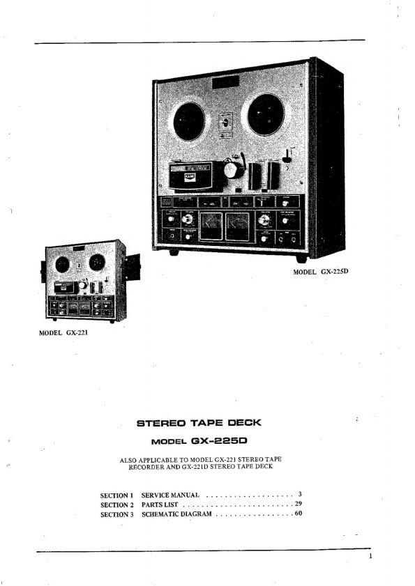
Akai GX-225D User manual

:
PART
SUSTEY

MODEL
GX-225D
MODEL
GX-221
STEREO
TAPE
DECK
°
MODEL
GX-225D
.
ALSO
APPLICABLE
TO
MODEL
GX-221
STEREO
TAPE
.
RECORDER
AND
GX-221D
STEREO
TAPE
DECK
SECTION
1
SERVICEMANUAL
........-.6-¢2
20
eee
3
SECTION
2
PARTSLIST
...........
ia
aesesets.
4s
fs
6
ase
SECTION
3.
SCHEMATIC
DIAGRAM
........-.--.+.---60

_
*
<
F
SECTION
1
SERVICE
MANUAL
TABLE
OF
CONTENTS
SPECIFICATIONS
2.000
cc
ccc
ee
center
te
eee
eee
eens
4
MEASURING
METHOD
......0000
cc
cece
e
cee
cere
creer
ee
ene
ee
aeeee
6
1.
TAPE
SPEED
DEVIATION
1.0...
00
ccc
ee
eee
eee
eee
eens
6
+
WOW
AND
FLUTTER
..
ox
ccc
pba
ecw
dane
a
a
ae
wo
we
Re
ae
ee
Oe
6
3,
FREQUENCY
RESPONSE
....-
0.0
ce
ete
eee
erence
etes
6
4
RICNAL
TO
NOISE
RATIO
\-soidw
doo
poh
oe
OR
eo
a
ee
Oe
6
5.
TOTAL
HARMONIC
DISTORTION
FACTOR
....-0..00
0000
eee
eer
tee
7
6.
CROSS
TALK
(Cross
talk
between
the
channels)
.
06-66
0
ee
eee
ee
es
q
@
ERASE
RATIO“
|
cect
6's
289
6S
Uk
OE
Ne
eS
TS
Oi we
eS
7
8.
POWER
OUTPUT
.....
bi
an
seg
this
duds
wee
bie
ut
RUE
ec
OHS
AR
VCE
ERAGE
SD
2
7
DISMANTLING
OF
UNIT
.......000
00
cece
cece
eee
ete
eet
eeees
‘eee
B
-
TRANSPORT MECHANISM
...-.-0-
00000
eect
e
eee
eee
ete
eee
ee
eens
10
if
FORWARD
PLAYBACK
RECORDING
MODE
......
Pe
er
ee
ee
ae
it
.
FAST
FORWARD/REWIND
MODE
......-
20sec
eee
ere
ee
teeters
11
:
BLOCK
DIAGRAM
OF
VOLTAGE
SUPPLY
CIRCUIT
TO
MOTOR
AT
EACH
MODE
....
!1
4.
SYSTEM
CONTROL
CIRCUIT
OPERATION
,..
0.2000
eee
eee
ee
eee
13
MECHANISM
ADJUSTMENTS
........-0
0-0-0
ee
eee
eee
cereeee
Sid
Sore
eee
14
1.
REEL
TABLE
HEIGHT
ADJUSTMENT
..
0.0...
0s
eee
eee
eee
eee
ets
14
2,
PINCH
WHEEL
PRESSURE
MEASURING
METHOD
Aiki
ated
rks
he
eine
bee
14
3.
BRAKE
TENSION
ADJUSTMENT
..
2.0.0
eee
ee
eter
eres
15
4,
SUPPLY
VOLTAGE
AND
TENSION
AT
VARIOUS
OPERATING
MODES
......----
15
HEAD
ADJUSTMENTS
.......
sos
se
ttn
od
athchv
a
du
Ns
fet
desc
Goad:
Saal
oS
taass
teh
16
1.
HEAD
HEIGHT
ADJUSTMENT
.......
0.0002
te
eee
reese
BAG
Parity
arg
ites
anette
16
2,
HEAD
AZIMUTH
ALIGNMENT
ADJUSTMENT
....
26-02
-
seer
ees
17
AMPLIFIER
ADJUSTMENTS
1.0.0.0
00
cece
ee
teeter
eee
eee
18°
1.
PLAYBACK
OUTPUT
LEVEL
ADJUSTMENT
......000
00
ee
eee
eee
rece
ree
18
3.
VU
METER
SENSITIVITY
ADJUSTMENT
.....
St
dnokudiend
upesoe
ata
peated
18
3.
HIGH
RANGE
VARIATION
CHECK
2.0.0.0
2.
cee
eee
et
eet
nneee
18
4.
RECORDING
LEVEL
ADJUSTMENT
..........
Bacio
Gaerne
ein
Aiae
&
Bitte
Bushs
21
5.
RECORDING
BIAS
FREQUENCY
MEASURING
METHOD
.........--
2022s
2
6.
RECORDING
BIAS
VOLTAGE
ADJUSTMENT
(Frequency
Response
Adjustment)
.-....-
21
_
AUTOMATIC
NOISE
REDUCTION
AMPLIFIER
ADJUSTMENTS
(GX-225D)
......-+++22
i
AN
RAMP:
ADTUSTMENT
6a.
as-eGice
XS
So
hae
ae
Sed
a
SES
Si
are
Ee
Be
22
‘>.
A.N.R.
OPERATION
AND
CHARACTERISTICS
...-...---00-035
Bie
phan
Readers
23
COMPOSITE
VIEWS
OF
COMPONENTS
.....
2-22-02
e
ete
rece
rts
tte
24

i.
SPECIFICATIONS
An
asterisk
next
to
a
figure
indicates
the
minimum
guaranteed
performance.
TRACK
SYSTEM
REEL
CAPACITY
TAPE
SPEED
WOW
AND
FLUTTER
FREQUENCY
RESPONSE
AKAIS.R.T.
Tape
Regular
Tape
SIGNAL
TO
NOISE
RATIO
'
HUM
AND
NOISE
DISTORTION
FACTOR
TONE
CONTROLS
Treble
Bass
CROSS
TALK
ERASE
RATIO
BIAS
FREQUENCY
BIAS
LEAK
HIGH
FREQUENCY
DEVIATION
Between
Channels
Between
FWD/REV
REC./P.B.
LEVEL
|
INPUTS
Mic
Input
Line
Input
.
Din
Input.
_
OUTPUTS
Line
Output
Din
Output
Speaker
Output
HEAD
PHONE
OUTPUT
REVERSING
TIME
FAST
FORWARD
AND
REWIND
TIME
MOTORS
Main
Motor
"
Reel
Motor
Erase
Head
4
track
2
channel
stereo/monaural
system
Up
to
7”
reel
7-1/2
ips(19
cm/sec.)
+0.7%(*+0.8%)
3-3/4
ips(9.5
cm/sec.)
£0.7%(*£0.8%)
1-7/8
ips(4.75
cm/sec.)
+0.7%(*4£0.8%)
Less
than
0.089%{*0.12%)
R.M.S,
at
7-1/2
ips
_
Less
than
0.12%
*0,25%)
R.M.S.
at
3-3/4
ips
Less
than
0,20%(*0.4%)
R.M.S,
at
1-7/8
ips
30
to
25,000
Hz
+3
dB
at
7-1/2
ips
30
to
20,000
Hz
+3
dB
at
3-3/4
ips
30
to
10,000
Hz
£3
dB
at
1-7/8
ips
30
to
23,060
Hz(*36
to
22,000
Hz}
+3
dB
at
7-1/2
ips
30
to
19,000
Hz(*38
to
18,000
Hz)
+3
dB
at
3-3/4
ips
30
to
9,000
Hz(*40
to
9,000
Hz)
+3
dB
at
1-7/8
ips
Better
than
50
dB(S3
dB
with
N.R.
process)
*
Better
than
48
dB
at
7-1/2
ips
*
Better
than
47
dB
at
3-3/4
ips
*
Better
than
45
dB
at
1-7/8
ips
*
Better
than
44
dB
at
Reverse
Mode
§
mV
Tone
Control
and
Main
Volume:
Min.
(Model
GX-221
only)
Less
than
1.5%{*3%)
at
1,000
Hz
“0”
VU
Recording
12 +2
dB(Max.)
and
—14
+2
dB(Min.)
at
10
kHz
12
+2
dB(Max.)
and
-10
+2
dB{Min.}
at
100
Hz
(Model
GX-221
only)
Better
than
65
dB(*58
4B)
monaural
Better
than
50
dB(*43
dB)
stereo
Better
than
70
dB
100
kHz
2
5%
Less
than
—20
VU
Within
2
dB,
using
an
8,006
Hz
3-3/4
ips
recorded
tape
at
7-1/2
ips
Within
3
dB,
using
an
8,000
Hz
3-3/4
ips
recorded
tape
at
7-1/2
ips
441.5
dB
0.2
m¥{*0.4
mV)
Impedance:
10
kQ
50
mV(*60
m¥)
Impedance:
150
kQ
2
mV(low)
and
50
mV{*60
mV}
(high)
1,228V
(4+
1dB)}
Impedance:
20kQ
0.4V
30
W
total
music
power
at
89
(GX-221
only)
20
W
continuous
power
at
82
{GX-221
only)
30
to
40
mV
at
82
2
to
6
sec.
85/65
sec.,
using
a
1,200
ft.
tape
at
50/60 Hz
3
speed
hysteresis
synchronous
motor
Type:
HC-16X
=
oh
Revolutions:
3,000/1,500/750
r.p.m.(50
Hz)
3,600/1,800/900
r.p.m.(60
Hz)
Two
6-pole
eddy
current
outer
rotor
motors
Type:
24X0-MR
Revolutions:
930
r.p.m.
(50
Hz)
1,120
r.p.m.
(60
Hz)
Type:
E4-250
Gap:
0.6
mm
Impedance;
1952
+
10%
at
100
kHz.
D.C.
Resistance:
3.52
ions

Recording
Head
Playback
Head
TRANSISTORS
Type:
R4-200
Gap:
44
+
15%
Impedance:
1,8702
at
100
kHz
D.C.
Resistance:
82
Type:
P4-200
Gap:
1,75y
15%
Impedance:
3
4
1k
at
1
kHz
D.C.
Resistance:
5002
LD3141.,.2
28C372(Y}
...1
28C871(F)..,12
28C945(Q)(R)...6
28C968(3}(4)
-..3
28C458LG(C)...6
STKOLS
...
2(GX-221
only)
28C971(2)(3)
RED...
2
28C1211(C}(D)
,
..
1
2SD223(G)(Y)..-
1
2SCTLICE)...4
DIODES
(N.R.
Amp.)
(N.R.
Amp.)
IN34A...7
5B2...1(GX-221
only)
10D1...3
WZ-240.,.1
lop4...1
WG-599
...
4(N.R.
Amp.}
POWER
SUPPLY
100
to
240
V
A.C.
50/60 Hz
POWER
CONSUMPTION
INSULATION
RESISTANCE
90W
Models
GX-225D,
GX-221D
135W
Model
GX-221
Mare
than
50
M@
INSULATION
DURABILITY
DIMENSIONS
WEIGHT
500V
D.C.
for
more
than
1
min.
duration,
430(W)
x
425(H)
x
230(D)
mm
(17.2"
x
17”
x
9.2")
20.5
kg(45.1
Ibs.)
Models
GX-225D,
GX-221D
22.5
kg(49.5
Ibs.)
Model
GX-221
NOTE:
Specifications
subject
to
change
without
notice.

ll.
MEASURING
METHOD
1,
TAPE
SPEED
DEVIATION
Frequency
counter
input
GX-225D
Line
output
Fig.
1
As
shown
in
Fig.
1,
connect
a
Frequency
Counter
to
the
Line
output.
Playback
a
1,000
Hz
pre-recorded
test
tape.
Take
a
frequency
counter
reading
at
the
beginning,
middle,
and
end
of
tape
winding
during
playback.
The
maximum
value
of
these
respective
readings
will
represent
tape
speed
deviation.
2.
WOW
AND
FLUTTER
GX-225D
Wow
and
Flutter
Line
output
Meter
input
Fig.
2
Method
A
As
shown
in
Fig.
2,
connect
the
Line
output
to
the
Input
of
a
Wow
and
Flutter
Meter.
Playback
a
3,000
Hz
pre-recorded
test
tape
and
take
a
wow
and
flutter
meter
reading
at
the
beginning,
middle,
and
end
of
tape
winding.
The
maximum
yalue
of
these
respective
readings
will
represent
the
wow
and
flutter.
Method
B
Supply
a
3,000
Hz
sine
wave
signal
from
an
Audio
Frequency
Oscillator
and
make
a
recording
on
a
blank
tape
at
the
beginning,
middle,
and end
of
tape
winding.
Rewind
and
playback
the
resultant
signal.
Measure
wow
and
flutter
with
a
Wow
and
Flutter
Meter.
(The
wow
and
flutter
value
of
Method
B
will
be
close
to
twice
that
of
Method
A.)
3,
FREQUENCY
RESPONSE
GX-225D
Line
Frequency
input
ane
Oscillator
ae
8
output
High
Sensitivity
V.T.V.M,
Fig,
3.
For
measuring
frequency
response,
connect
instru-
ments
as
shown
in
Fig.
3
and
proceed
as
follows:
1)
Supply
a
1,000
Hz
sine
wave
to
the
Line
input
from
an
Audio
Frequency
Oscillator
through’
an
Attenuator.
2)
Set
recorder
to
recording
mode
and
turn
recording
level
contro!
volume
and
line
output
level
control
volume
to
maximum,
Adjust
attenuator
to
obtain
a+4
dB
V.T.V.M.
reading.
3)
Under
conditions
described
in
2)
above,
re-adjust
attenuator
so
that
the
Line
Output
is
—16
dB,
and
record
30
to
22,000Hz
at
7-1/2
ips
spot
fre-
quencies.
4)
Rewind
the
tape
and
playback
from
the
beginning.
Take
V.T.V.M.
spot
frequency
readings
and
plot
values
on
a
graph.
.
NOTE:
When
measuring
frequency
response,
new
tape
should
be
used.
4,
SIGNAL
TO
NOISE
RATIO
GX-225D
High
Sensitivity
Line
output
VIVM,
Fig.
4
As
shown
in
Fig.4,
connect
a
High
Sensitivity
V.T.VM.
to
the
Line
output.
Playback
a
250
Hz
“Q”
VU
pre-recorded
test
tape
and
mieasure
the
output.
Then
remove
the
tape
and
measure
the
noise
level
under
the
same
condition,
Convert
each
of
the
measured
values
into
decibels.

-
§,
TOTAL
HARMONIC
DISTORTION
GX-225D
Line
input
—Line
output
Audio
Frequency
Oscillator
Distortion
Meter
Fig.
5
Connect
the
measuring
instruments
as
shown
in
Fig.
5
and
record
a
1,000
Hz
sine
wave
signal
at
“0”
VU.
Playback
the
resultant
signal
and
measure
the
overall
distortion
factor.
Measure
the
noise
level
of
the
tape
recorder
without
the
tape.
Connect
the
audio
fre-
quency
oscillator
directly
to
the
distortion
meter
for
measurement
of
the
distortion
factor
of
the
oscil-
lator.
The
required
distortion
factor
can
be
obtained
from
the
results
of
the
above
measurement
by
the
following
formula:
do
=d—di
—d2
where,
do
=
Required
distortion
factor
d
=
Overall
distortion
factor
di
=
Noise
level
d2
=
Distortion
factor
of
the
oscillator
NOTE:
When
measuring
the
distortion
factor,
new
’
tape
should
be
used.
6.
CROSS
TALK
|
(Cross
talk
between
the
channels}
(TAPE)
REV
oy
Se
ees
GS
TAPE
DIRECTION
Fig.
6
As
shown
in
Fig.
6,
first
record
a
1,000
Hz
sine
wave
signal
on
Track
No.
3
at
+3
VU
level.
Next,
record
under
a
non-input
condition.
Then,
playback
the
tape
on
Tracks
No.
3
and
4
(reversed
condition
of
tape)
through
the
B.P.F,
(band
pass
filter
sensitivity
...
1:1)
and
obtain
a
ratio.
between
the
two
from
the
following
formula:
,
Eo
E2—-E1
where,
C
=
Desired
cross
talk
ratio
(dB)
Bo
=
1,000
Hz
signal
output
level
[i
’
Be
=
1,000
Hz
cross
talk
level
Ei
=Non-input
signal
recorded
level
Bax
'C
=
20
log
(dB)
7.
ERASE
RATIO
As
shown
in
Fig.4,
connect
a
High
Sensitivity
V.T.V.M.
to
the
Line
ouput.
Playback
a
virgin
tape
and
take
a
V.T.V.M.
reading
of
the
output
level.
Next,
record
a
1,000
Hz
sine
wave
signal
at
+3
VU,
‘then
playback
this
recorded
signal
and
take
a
V.T.V.M.,
reading
of
the
output
level.
Next,
using
this
pre-recorded
tape,
record
under
a
non-input
condi-
tion
and
take
a
reading
of
the
noise
level
output
of
the
erased
signal
and
obtain
a
ratio
between
the
two
from
the
following
formula:
Eo
Er
=
20
log
(dB)
E2-E1
where,
Er
=
Desired
erase
ratio
(dB)
Eo
=
1,000
Hz
signal
output
level
Ez
=
Non-input
signal
recorded
level
Ex
=
Virgin
tape
noise
output
level
8.
POWER
OUTPUT
(GX-221
only)
High
Sensitivity
output
V.T.VM.
Fig.
8
As
shown
in
Fig.
7,
connect
an
89
dummy
load
resistor
to
the
speaker
output
and
connect
this
terminal
to
a
High
Sensitivity
V.T.V.M.
Playback
a
250Hz
“0”
VU
pre-recorded
test
tape
and
take
a
V.T.V.M.
reading
of
the
output
level.
The
resultant
output
can
be
obtained
from
the
above
measurement
by
using
the
following
formula:
al
-2
P=
Ww)
where,
P
=
Desired
power
output
(watts)
E
=
Measured
voltage
(R.M.S.)
R=
8&Q

Il.
DISMANTLING
OF
UNIT
In
case
of
trouble,
etc.
necessitating
disassembly,
please
disassemble
in
the
order
shown
in
photographs.
Reas-
semble
in
reverse
order.
SIDE
PLATE
h
REAR
PLATE

MECH.
BLOCK
&
MECHANISM
ADJUSTMENT
LOWER
FRAME
cena
-
P.B.
AMP.
P.C.
BOARD
REC.
AMP.
P.C.
BOARD
CARD
HOLDER
7
SCREWS

IV.
TRANSPORT
MECHANISM
Fig.
10
F.FWD/RWD
MODE
10

I
1.
FORWARD
PLAYBACK
RECORDING
2.
FAST
FORWARD/REWIND
MODE
MODE
(Refer
to
Fig.
9)
(Refer
to
Fig.
10)
Setting
Recording/Playback
lever
(A)
to
playback
1)
Setting
Fast
Forward/Rewind
lever
(B)
to
Fast
position
causes
brake
lever
(E’)
to
move
in
the
Forward
or
Rewind
position
causes
brake
lever
direction
of
the
arrow
and
release
the
brake
of
both
(E')
to
move
in
the
direction
of
the
arrow,
and
torque
motors,
and
at
the
same
time,
operation
micro
release
the
brake
of
both
torque
motors,
and
at
switch
(SW-006)
is
turned
ON
by
lever
(G),
and
the
the
same
time,
operation
micro
switch
(SW-006)
is
torque
motors
begin
to
rotate
in
the
direction
of
the
-
turned
ON
by
lever
(G)
and
the
torque
motors
arrows.
Also-the
capstan
contacts
the
pinch
roller
and
begin
to
rotate
in
the
direction
of
the
arrows.
the
tape
is
transported
at
constant
speed.
2)
For
fast
forward
or
rewind,
the
mechanical
opera-
tion
is
the
same,
but
the
voltage
supply
is
different
at
each
mode.
(Refer
to
Chart
2)
3.
BLOCK
DIAGRAM
OF
VOLTAGE
SUPPLY
CIRCUIT
TO
MOTOR
AT
EACH
MODE
TAPE
SPEED
SW.
A.C.
100VE
7-w-3-,
—
1-%
AC,
HOV
©
MAIN]
MOTOR
I—o_¢
0
Swolda
—
50Hz2—~—-GOHz
P
—sHe—
NORMAL
CLOSED
CONTACT
S0Hz———60Hz
;
—t-
NORMAL
OPEN
CONTACT
Fig.
11
NORMAL
PLAYBACK
MODE
A.C,
COM.
O
50Hz—---GOHz
TAPE
SPEED
SW.
A.C,
LOOV
©
AS.
OV
o
REVS
swolda
S0H2——-
GOHZ
ie
NORMAL
CLOSED
CONTACT
S0Hz——~—-60Hz
—il—
NORMAL
OPEN
CONTACT
Fig.12
REVERSE
PLAYBACK
MODE
A.C,
COM.
©
11

50Hz—=-60Hz
TAPE
SPEED
SW,
Ac,
100V0
7-3-3},
=e
1-%
AC
TOV
©
MAIN;
MOTOR
O26
©
swoida
50Hz—-~
6OHz
REVS
4.C.
COM,
O
—ai—
NORMAL
CLOSED
CONTACT
50Hz——60Hz
1
NORMAL
OPEN
CONTACT
Fig.
13.
F.FWD
MODE
‘BOH2—-GOHz
TAPE
SPEEO
SW.
|
Y,
7-3-3,
—
1-%
Swoica
'
BOHz——-60Hz
REVS
A.C,
COM,
©
—sit<—
NORMAL
CLOSED
CONTACT
50Hz———-60Hz
—k—
NORMAL
OPEN
CONTACT
Fig.14
RWD
MODE
12
oe

€020)
AT/NG
GROUNDS
|
Mode
ransis-
.
|
tor
|TRO201/
TRO202
TRO203/FRO401
TR204
|
|
|
Normal
|
orp
|
oN
|
OFF
OFF
|
OFF
B.
1
Ree
|
on
|
orF
|
on
|
on
|
oN
Chart
1
4,
SYSTEM
CONTROL
CIRCUIT
OPERATION
1)
Tension
Relay
Operation
The
tension
relay
functions
to
switch
the
supply
voltage
only
when
the
main
motor
is
first
started
or
at
reverse
time
when
the
starting
torque
changes
until
stability
is
obtained.
The
tension
relay
also
prevents
strong
tension
from
being
applied
to
the
tape
when
tape
direction
is
changed
by
supplying
uniform
voltage
to
both
torque
motors.
2)
Mute
Relay
Operation
Because
tape
travel
is
show
when
the
machine
is
first
switched
to
or
from
Forward
and
Reverse,
the
mute
relay
mutes
the
line
output
signal
until
proper
main
motor
revolutions
are
reached.
3)
System
Controi
Operation
In
Schematic
1,
at
Forward
Playback
time,
because
transistor
TRO202
base
bias
is
high
when
compared
with
transistor
TRO201,
TRO202
is
held
at
ON
condition.
Consequently,
the
collector
_
voltage
of
TRO202
is
low,
and
transistor
TRO203
is
OFF,
Also
because
the
condenser
C0202
is
charged
by
the
collector
voltage
of
transistor
TRO201,
the
base
bias
of
transistor
TRO401
as
well
as
TR204
is
low
and
is
held
at
OFF
condition.
When
the
Reverse
Button
is
depressed,
or
the
sensing
tape
passes
the
reverse
sensing
pole,
the
base
of
transistor
TRO202
is
grounded,
the
collec-
tor
voltage
of
TRO202
increases
and
TRO203
is
turned
ON,
and
because
Rev.
Relay
RLO201
_
operates,
main
motor
reverse
revolutions
begin.
REVRSE
PLUNGER
SOLENOID
B.S,
9p.c,
24V
TR204
MUTE
RELAY
RL206
Schematic
1
Also
because
of
the
TRO202
collector
voltage
increase,
the
charge
cument
which
has
passed
diode
DO204
as
well
as
resistors
RO401
and
R218
and
also
the
internal
impedance
of
transistors
TRO401
and
TR204
flows
to
condenser
C0205,
and
while
this
current
is
flowing,
TRO401
and
TR204
is
mdfintained
at
ON
condition,
and
Tension
Relay
RLO401
as
well
as
Mute
Relay
RL201
operates.
:
When
the
main
motor
begins
reverse
revolutions
and
proper
tape
speed
is
reached,
the
charge
of
condenser
C0205
will
be
stopped,
TRO401
and
TR204
base
bias
will
disappear
and
these
two
transistors
are
turned
off,
the
tension
relay
as
well
as
the
Mute
Relay
is
turned
off,
and
proper
reverse
mode
operation
begins.
During
reverse
playback
when
the
FWD
Button
is
depressed
or
the
sensing
tape
passes
the
FWD
sensing
pole,
the
base
of
transistor
TRO201
is
grounded,
TRO201
is
turned
off
and
the
collector
voltage
increases.
Accordingly,
transistor
TRO202
base
bias
becomes
high,
TRO202
is
turned
ON
and
the
collector
voltage
decreases,
At
this
time,
TRO203
is
turned
OFF,
and
Rev,
Relay
RLO201
is
also
turned
OFF.
Thus,
main
motor
revolutions
are
switched
to
normal
playback
direction,
Also
because
of
the
TRO201
collector
voltage
increase,
as
at
reverse
time,
charge
current
flows
to
condenser
C0202,
and
transistor
TRO401
and
TR204
are
turned
ON.
Consequently,
Tension
Relay
RLO401
as
well
as
Mute
Relay
RL201
operates.
The
main
motor
begins
forward
revolutions
and
when
proper
tape
speed
is
reached,
condenser
C0202
charge
will
be
stopped,
the
Tension
Relay
as
well
as
Mute
Relay
is
turned
OFF,
and
proper
forward
mode
opera-
tion
begins.
At
Stop
or
Recording
mode,
voltage
is
supplied
to
TRO202
base,
and
because
Reverse
Button
and
sensing
tape
is
irrelevant,
main
motor
revolutions
are
always
in
forward
playback
direction.
i
13

V.
MECHANISM
ADJUSTMENTS
Nie
HHL
om
a
Els
tit
/
REEL
TABLE
HEIGHT
REEL
TABLE
ADJUSTMENT
SCREWS
~
Fig,
15
1,
REEL
FABLE
HEIGHT
ADJUSTMENT
As
shown
in
Fig.
15,
loosen
reel
table
height
adjust-
ment
screws,
and
adjust
reel
table
height
by
moving
table
in
direction
of
arrow
and
positioning
so
that
ne
tape
winds
in
the
center
of
the
reel.
2,
PINCH
WHEEL
PRESSURE
MEASURING
METHOD
Measure
pinch
wheel
pressure
with
a
tension
gauge
as
shown
in
Fig.
16.
Read
the
value
on
the
tension
gauge
as
soon
as
the
pinch
wheel
separates
from
the
tape
_—
and
tape
travel
stops.
Ideal
pinch
wheel
pressure
is
Fig.
17
1.8
kg.
14

3.
BRAKE
TENSION
ADJUSTMENT
1)
As
shown
in
Fig.
17,
use
a
60
mm
diameter
tape
wound
on
a
5”
reel
and
measure
the
brake
tension
with
a
tension
gauge.
Ideal
brake
tension
is
from
300
to
370
grams.
2)
Brake
tension
adjustment
can
be
made
as
follows:
(Refer
to
Fig.
18)
a)
Change
position
of
suspended
spring
(a).
b)
Loosen
screws
(b)
and
(c)
and
adjust
the
vertical
position
of
spring
suspension
metal
(d).
c)
Loosen
screws
(e)
and
(f)
and
adjust
the
horizontal
position
of
brake
band
suspension
metal
(g).
d)
Only
the
left
side
is
shown
in
Fig.
18,
but
the
right
side
must
be
adjusted
in
the
same
way.
NOTE:
In
making
brake
tension
adjustment,
at
all
modes
except
stop
mode,
confirm
that
the
brake
band
completely
separates
from
the
cloth
tape
on
the
brake
drum.
(Refer
to
Fig.
18)
Fig.
18
4.
SUPPLY
VOLTAGE
AND
TENSION
AT
VARIOUS
OPERATING
MODES
orque
Motor
|
Left
Side
Right
Side
Mode
30
V
(34
V)
60
V
(68
V)
|
Normal
P.B.
608
200
g
60
V
(68
V)
30
V
(34
V)
Reverse
P.B.
200
g
60g
5.8V(6V)
|
94.2
V
(103
Vv)
roe
Sg
460.to
480
g
94.2
V
(103
V)
5.8V(6V)
ROP
460
to
480
g
15¢g
Tension
Relay
at)
45
V(51
V)
45V
(51
V)
Operating
Time
100g
100g
The
voltage
shown
in
parentheses
are
at
60
Hz.
Chart
2
15

VI.
HEAD
ADJUSTMENTS
RECORDING
PLAYBACK
HEAD
HEAD
—s
ee
aE
=
|
Fig.
19
1.
HEAD
HEIGHT
ADJUSTMENT
3)
Playback
Head
1)
Erase
Head
a)
At
Forward
Playback
mode,
adjust
playback
head
height
by
turning
screws
(F)
(G)
and
(H)
shown
in
Fig.
19
to
left
and
right
until
the
upper
edge
of
the
tape
is
the
same
height
as
the
upper
edge
of
the
left
channel
playback
head
At
Playback
mode,
loosen
screws
(A)
shown
in
Fig.
19
and
adjust
head
height
so
that
the
upper
edge
of
the
tape
is
about
0.1
mm
lower
than
the
upper
edge
of
the
left
channel
erase
head
core.
2)
Recording
Head
core.
At
Playback
mode
adjust
recording
head
height
by
b)
At
Reverse
Playback
mode,
adjust
playback
turning
screws
(B) (C)
and
(D)
shown
in
Fig.
19
to
head
height
by
turning
screw
(E)
shown
in
Fig.
19
to
left
and
right
until
the
lower
edge
of
the
tape
is
the
same
height
as
the
lower
edge
of
the
right
channel
playback
head
core.
left
and
right
until
the
upper
edge
of
the
tape
is
the
same
height
as
the
upper
edge
of
the.
left
channel
recording
head
core.
16

rer
2.
HEAD
AZIMUTH
ALIGNMENT
ADJUSTMENT
1)
Playback
Head
a)
Connect
a
high
sensitivity
V.T.V.M.
to
the
line
output
terminals.
b)
Set
both
the
Tape
Speed
Switch
and
Equalizer
Switch
to
7-1/2ips
(19
cm/sec),
depress
STEREO
Track
Selector,
and
set
the
Monitor
Switch
to
TAPE
position.
c)
In
case
of
model
GX-225D,
set
Noise
Reduc-
tion
Switch
to
OFF
position.
d)
Playback
an
8,000
Hz
3-3/4
ips
recorded
Am-
pex
Alignment
test
tape.
e)
At
Forward
Playback
mode,
turn
Azimuth
Alignment
Screw
(F)
shown
in
Fig.
19
to
obtain
maximum
line
output
level
on
both
channels.
f)
After
the
adjustment
in
Item
e)
above
has
been
completed,
loosen
screws
(I)
shown
in
Fig.
19
and
move
the
head
gap
side
of
the
playback
head
to
left
and
right.
When
tension
is
applied
to
the
supply
reel
side
and
the
line
output
level
of
both
channels
do
not
fluctuate,
(maximum
allowable
fluctuation
within
+0.5/—O
dB)
fix
screws
(I)
to
maintain
this
condition.
g)
At
reverse
playback
mode,
make
the
same
adjustment
as
outlined
above
until
the
line
output
level
of
both
channels
do
not
fluctuate.
2)
Recording
Head
a)
Connect
an
audio
frequency
oscillator
to
the
line
input
terminals,
and
connect
a
high
sensiti-
vity
V.T.V.M.
to
the
line
output
terminals
and
load
a
blank
tape.
b)
Set
both
the
Tape
Speed
Switch
and
Equalizer
switch
to
7-1/2ips
(19cm/sec.),
depress
STEREO
Track
Selector,
and
set
the
monitor
switch
to
TAPE
position.
c)
Record
a
16,000
Hz
audio
frequency
at
—10
dB
recording
level.
d)
At
recording
mode,
turn
Azimuth
Alignment
Adjustment
Screw
(D)
shown
in
Fig.
19
to
left
and
right
until
the
line
output
level
of
both
channels
is
maximum
and
does
not
fluctuate.
e)
After
completing
adjustment
in
Item
d)
above,
adjust
gap
side
of
recording
head
by
bending
installation
angle
(J)
shown
in
Fig.
19
to
left
and
right
until
the
line
output
level
of
both
channels
do
not
fluctuate
(maximum
allowable
fluctuation
within
+0.5/—0
dB)
when
tension
is
applied
to
the
supply
reel
side.
3.To
obtain
best
results,
repeat
adjustments
outlined
in
paragraphs
1
and
2
above
2
or
3
times.
New
blank
tape
should
be
used
when
making
these
adjustments.
17

Vil.
AMPLIFIER
ADJUSTMENTS
RIGHT
CH.
VU
METER
SENSITIVITY
ADJ.
VR202b
SKB
RIGHT
CH.
P.B.LEVEL
ADJ.
VR20ib
20KB
RIGHT
CH,
REC.
LEVEL
ADJ.
VR30Ilb
20KB
LEFT
CH.
VU
METER
SENSITIVITY
ADJ.
VR202
5KB8
LEFT
CH.
PB.
LEVEL
ADJ.
VR20I
20KB
LEFT
CH.
REC,
LEVEL
ADJ.
VR30!
20KB
LEFT
CH.
REC.
BIAS
VOLTAGE
ADJ.
TCSOS
7OP
RIGHT
CH,
REC.
BIAS
VOLTAGE
ADJ.
TCS5O06
70P
®
:
PLAYBACK
AMP,
RC,
BOARD
MS-5022
@®
;
RECORDING
AMP.
P.C.
BOARD
MS-5023
©
;
OSCILLATOR
P.Cc.
BOARD
MS-5025
GX-225D
High
Line
Sensitivity
V.T.V.M.
output
Fig.
21
_—
.
PLAYBACK
OUTPUT
LEVEL
ADJUSTMENT
1)
Connect
a
high
sensitivity
V.T.V.M.
to
the
line
output
terminals.
2)
Set
both
the
Tape
Speed
Switch
and
Equalizer
Switch
to
7-1/2
ips
(19
cm/sec.),
depress
STEREO
Track
Selector
and
set
the
Monitor
Switch
to
TAPE
position.
3)
In
case
of
model
GX-225D,
set
Noise
Reduction
Switch
to
OFF
position.
4)
Playback
a
250
Hz
‘‘0”
VU
pre-recorded
test
tape.
5)
Adjust
P.B.
Amp.
P.C.
Board
playback
level
adjustment
semi-fixed
resistors
VR201
20
kB
(Left
Channel)
and
VR20lb
20kB
(Right
Channel)
shown
in
Fig.
20
to
obtain
a
High
Sensitivity
V.T.V.M.
indication
of
4
dB
(1.228
V)
Fig.
20
2.
VU
METER
SENSITIVITY
ADJUSTMENT
After
the
playback
output
level
adjustment
has
been
completed,
adjust
P.B.
Amp.
P.C.
Board
VU
meter
sensitivity
adjustment
semi-fixed
resistors
VR202
5kB
(Left
Channel)
and
VR202b
5
kB
(Right
Channel)
shown
in
Fig.
20
to
obtain
a
VU
meter
indication
of
“0”
VU
on
both
channels.
3.
HIGH
FREQUENCY
DEVIATION
CHECK
1)
Between
Channels
When
an
8,000Hz
3-3/4
ips
Ampex
Alignment
test
tape
is
played
back,
check
to
confirm
that
the
difference
in
high
range
output
level
between
the
left
and
right
channel
is
within
2
dB.
2)
Between
FWD
and
REV
Playback
Playback
and
Alignment
test
tape
and
check
to
confirm
that
the
difference
in
high
range
level
output
between
FWD
and
Reverse
playback
mode
is
within
3
dB.
3)
If
Items
1)
and
2)
above
are
not
within
specifica-
tions,
repeat
Head
Azimuth
Alignment
adjust-
ment.
'
18

PB.
LEVEL
ADJ.
P.B.
LEVEL
AD.
VR201
20KB
VR20ib
20KB
VU
METER
SENSITIVITY
ADJ.
VU
METER
SENSITIVITY
ADJ.
VR202
5KB
VR202b
5KB
LEFT
CHANNEL
RIGHT
CHANNEL
Fig.22
P.B.
AMP.
P.C.
BOARD
(Face
Side)
Ears
[po
LW
iex-22t_
|
X
| O
|
x
JO
|
Se
CO
lx-2e50
|
X
[Oo
[oO
|
x
|
Fig.
23
P.B.
AMP.
P.C.
BOARD
MS-5022
(Reverse
Side)
;
TR20I,
202---
28ca7!
©
TR203
vrs
2s0945
© ®
Audio
GX-225D
|
Left
High
Frequency
Line
Line
Sensitivity
Osci
input
output
5.
V.T.V.M.
scillator
Right
Fig.
24
19

LEFT
CH.
REC,
LEVEL
ADJ.
RIGHT
CH.
REC.
LEVEL
ADJ.
VR30!1
20KB
VR30ilb
20KB
Fig.
25
REC.
AMP.
P.C.
BOARD
(Face
Side)
TR301,
302,303,304
“2SC871
©
TR305---
2SC96B@EQ)
Fig.
26
.
REC.
AMP.
P.C.
BOARD
MS-5023
(Reverse
Side)
FROM
OSCILLATOR
REC.
HEAD
FREQUENCY
AUDIO
FREQUENCY
ere
©O
OSCILLATOR
OSCILLOSCOPE
Fig.
27
‘f,
20
This manual suits for next models
2
Table of contents
Other Akai Tape Deck manuals

Akai
Akai GX-210D Operating and installation instructions

Akai
Akai GX4000D Troubleshooting guide

Akai
Akai GX-747 dbx User manual

Akai
Akai GX-630D User manual

Akai
Akai GX-265D User manual

Akai
Akai 1721W User manual

Akai
Akai GX-215D User manual

Akai
Akai GX4000D User manual

Akai
Akai GX-260D User manual

Akai
Akai GX-280D-SS User manual
Popular Tape Deck manuals by other brands

Sony
Sony DTC-670 operating instructions

Technics
Technics SV-DA10 operating instructions

Quantum
Quantum Scalar i500 Replacement guide

Pioneer
Pioneer RT-1011L Service manual

Onkyo
Onkyo TA-6510 instruction manual

Romac Industries Inc.
Romac Industries Inc. Sewer Pipe Tapping Machine Instruction and maintenance manual