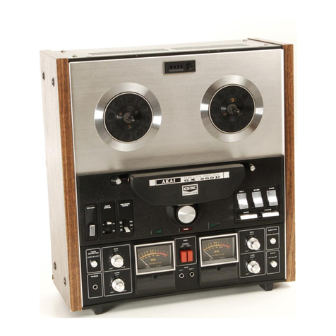
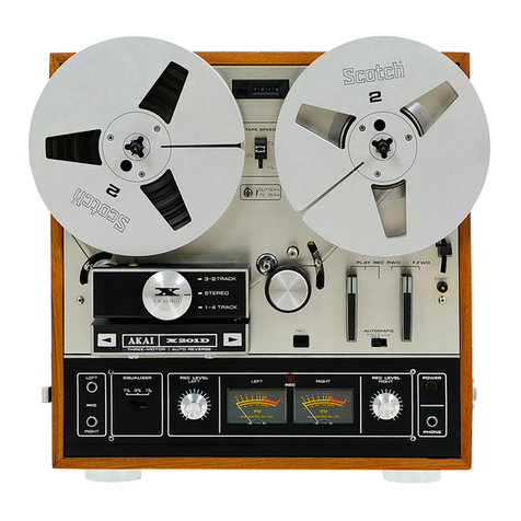
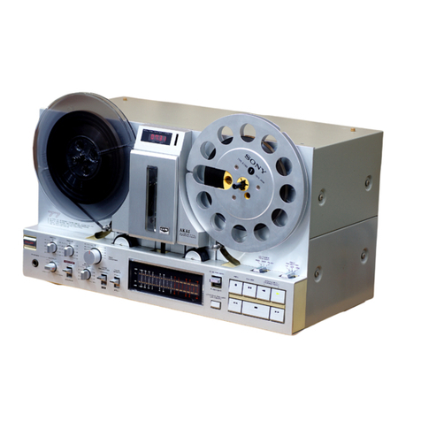
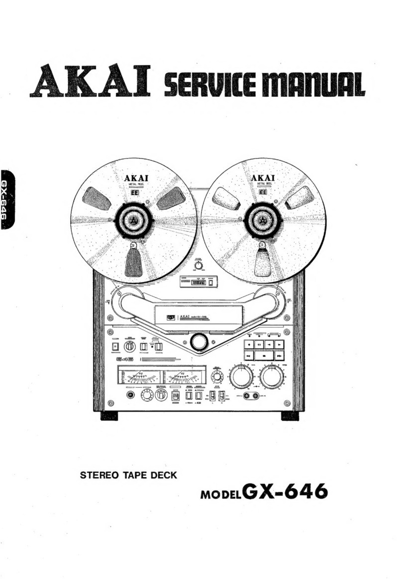
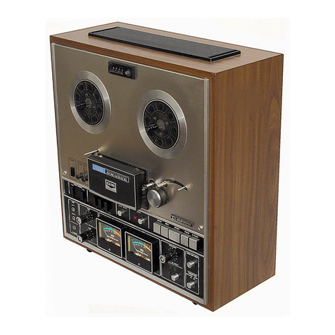
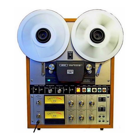
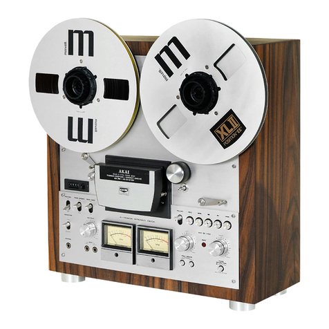
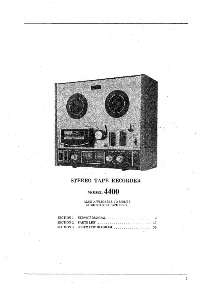
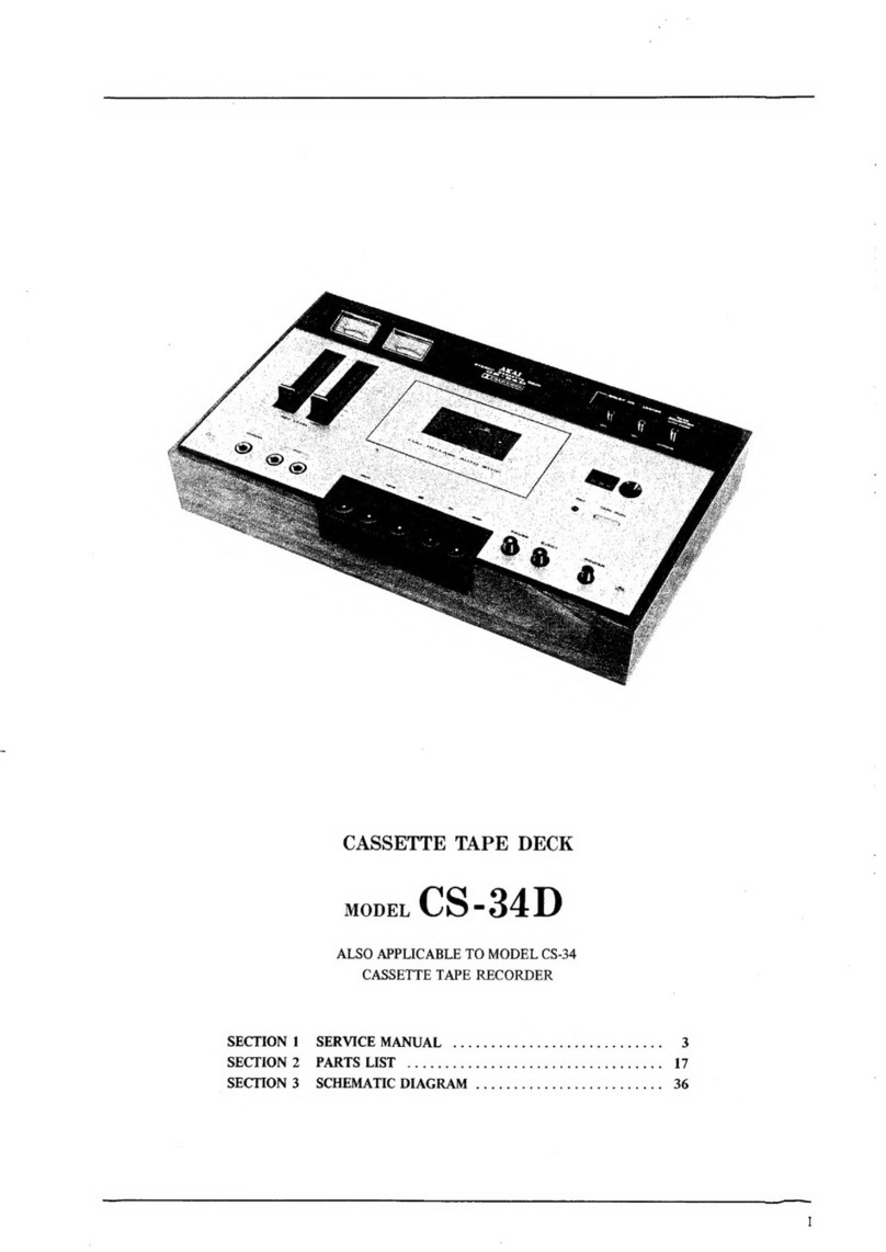
Akai GX-265D Troubleshooting guide

SERVICE
MANUAL
iL
PART
SUSTES
AKAI
STEREO
TAPE
DECK
MODEL
CsM=e@65
|

STEREO
TAPE
DECK
mopEL
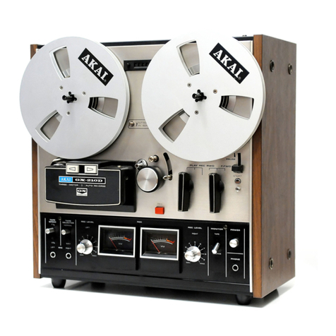
GX-265D
SECTION
1
SERVICE
MANUAL
SECTION
2
PARTS
LIST.
...........


SECTION
1
SERVICE
MANUAL
TABLE
OF
CONTENTS
L
SPECIFICATIONS
*
i
i5hsshatiscichsssctaceh
hess
acesstescttis
sas
caanes
Meaveccaseesoibeves
thensardanatech
edetivcbiniadees
eee
Il.
DISMANTLING
OF
UNIT
III.
ARRANGEMENT
OF
PRINCIPAL
PARTS.
.u.....ccccccessssesssesesseseeseseserecsesenenenensesecessesnenseaeeeeeeaseesinaeess
7
IV.
MECHANISM
ADJUSTMENT.
............:cccccsscccsssessssescsscsessssscssesssseeseseesesesssenecssssseecseseesreseseeeeseeesssenecarsesanes
8
POSITION
ADJUSTMENT
OF
PINCH
WHEEL
SOLENOID
SL-3
o...sesssscsecsssessseesesseeteeseeneeeees
PINCH
WHEEL
POSITION
ADJUSTMENT
AT
STOP
MODE
_
.uw..seccceseeeeesstseersseaeeeneenenerene
PINCH
WHEEL
PRESSURE
ADJUSTMENT
...---sssssesssssssssessseersesesenesesesenees
POSITION
ADJUSTMENT
OF
PLAY
HOLD
MICROSWITCH
SW-11
SLIDE:
ADJUSTMENT
|
corsscssnsscerccosstcconcosssnssosnsestsnosocssvesncneiesignaasasoovbsnsdcvessessedenst
POSITION
ADJUSTMENT
OF
QUICK
PLATE
oesssscesssessesseeesseesseerecesseseneaereeseenesesesnesenerieansennes
POSITION
ADJUSTMENT
OF
RECORDING
MICROSWITCH
SW-5
POSITION
ADJUSTMENT
OF
BRAKE
SOLENOID
SL-2
oseseseessesesssestseeeeseessneessesereeeesenenenens
9,
POSITION
ADJUSTMENT
OF
BRAKE
SOLENOID
MICROSWITCH
SW-8
.......sseeeee
cette
11
10.
BRAKE
TENSION
ADJUSTMENT.
.......::c:cscccsssssesesessessssssssssesesessseseseneneneseseusseecsnseaeenensereeeseerasesenanes
11.
PAUSE
ADJUSTMENT
.u..scsccccccssssssecscesssssesessssesencsesensneeesensseseneeseseaeenesesnneenensaes
tissasscguegnaueaadvnciestseess
12.
POSITION
ADJUSTMENT
OF
REVERSE
SOLENOID
SL-1
ooesessesssseesssseesssesesesesseeneeeneeeenenenes
13.
D
SWITCH
LEVER
ADJUSTMENT
......:..:::c:csssessssessetsseeeseteeeeseeerseeeseaesens
14.
INSTALLATION
POSITION
ADJUSTMENT
OF
REVERSE
JOINT
o..-sesssecseeeseseteteseneeenes
15,
INSTALLATION
POSITION
ADJUSTMENT
OF
HEAD
SWITCH
SW-3
16.
CAPSTAN
SHAFT LOOSE
PLAY
ADJUSTMENT
osesesssssssessecssssssesesesseesesseessaesensasasseceseneanneerngns
17.
OPERATING
POSITION
ADJUSTMENT
OF
TENSION
MICROSWITCH
SW-14
18.
TAPE
GUIDE
HEIGHT
ADJUSTMENT.
.....csccccscessscssesesesesseseesesesenessersesesesesenenssseseesenseneceasens
19.
REEL
TABLE
HEIGHT
ADJUSTMENT
oosesssssssscssssssescssssssesstessscensesnecssecesnessvesnecsanssneeessensecsnsente
HEAD
ADJUSTMENT.
-sccisciseveis
ceased
vosxegeteds
soit
bh
ncseibe
hous
cacts
heaveeiesvzchecadeanetaecesasareccutqua
de
aanenvassiansecenteeceeresdoee
AMPLIFIER
SYSTEM
ADJUSTMENT
.....-:::cccccccccccecceeeeescscncescessessscnensnnneeeneceneesecessesnaceecseseersceeacaserteseeeeses
1.
DC
POWER
SUPPLY
VOLTAGE
ADJUSTMENT.
-----s:sesesesee
Sadan
bedverddabaveieivvsrdl
deevns
seed
2.
TAPE:
SPEED
ADJUSTMENT.
cisicciestisicceccssscclesertiasacesadsnnsadnesenstedevencteeapescnancensoesendescnenasctnandecdetiedeedes
3.
RECORDING
AND
PLAYBACK
AMPLIFIER
ADJUSTMENT
.u.-s.ccesscccscesssesstetenntee
se
eeseeeenacenes
VII.
DC
RESISTANCE
OF
VARIOUS
COILS
ou.ccescccccssssessccssseseseesssesesecescenceescssedeseseseeeeeeaeseseseneraena
ee
sensnssenenss
VIIT.
CLASSIFICATION
OF
VARIOUS
P.C
BOARDS
oveseseeececeecssesesessseesereseneeneeesenseseseseseeseneaesnsg
eee
ciesenenenees
1.
RELATION
OF
P.C
BOARD
TITLE
AND
NUMBER
...s...eeccecsccsssesssesteeeeeeteetecnseecssennses
oe
eeersnersnenes
2.
COMPOSITION
OF
VARIOUS
P.C
BOARDS
.
0...
ce
cceeceesececereeesseesesseecssessaersseecesaeesneneneeaessanesseaees
SN
AARwWH
<<
For
basic
adjustments,
measuring
methods,
and
operating
principles,
refer
to
GENERAL
OPERATING
PRINCIPLES
AND
ADJUSTMENTS.
|
|
|
|
|
|
|
1.
SPECIFICATIONS
ee
ee
AEN
NESE
IRIINSONES
An
asterisk
next
to
a
figure
indicates
the
minimum
guaranteed
performance.
TRACK
SYSTEM
TAPE
SPEED
WOW
AND
FLUTER
TOTAL
WOW
AND
FLUTTER
FREQUENCY
RESPONSE
HARMONIC
DISTORTION
TOTAL
HARMONIC
DISTORTION
4
track
2
channel
stereo/monaural
system
7-1/2
and
3-3/4
ips
+0.7%
*7-1/2
ips
(19
cm/sec)
+0.8%
*3-3/4
ips
(9.5
cm/sec)
+1.0%
“Less
than
0.06%
WRMS
at
7-1/2
ips
Less
than
0.09%
WRMS
at
7-3/4
ips
*Less
than
0.1%
RMS
at
7-1/2
ips
(FWD/REV)
*Less
than
0.15%
RMS
at
3-3/4
ips
(FWD/REV)
*Less
than
0.1%
at
7-1/2
ips
(FWD/REV)
*Less
than
0.15%
at
3-3/4
ips
(FWD/REV)
30
to
25,000
Hz
+3
dB
at
7-1/2
ips
30
to
19,000
Hz
+3
dB
at
3-3/4
ips
(Using
AKAI
LN-150-7
tape)
*30
to
22,000
Hz
+3
dB
at
7-1/2
ips
*30
to
18,000
Hz
+3
dB
at
3-3/4
ips
Less
than
0.5%
*Less
than
1.0%
at
7-1/2
ips
*Less
than
2.0%
at
3-3/4
ips
SIGNAL
TO
NOISE
RATIO
*Better
than
50
dB
TOTAL
SIGNAL
TO
NOISE
RATIO
*Better
than
47
dB
OUTPUT
LINE
*0.775V
(0
dBm
+1.0
dB/0
dBm
+1.5
dB,
FWD/REV)
DIN
0.5V
PHONE
30
mV/8
ohm
At
playback
of
a
700
Hz
“0”
VU
pre-recorded
test
tape.
(Output
Volume
at
maximum)
INPUT
MIC
More
than
0.25
mV/5
k
ohm
LINE
More
than
70
mV/150k
ohm
DIN
More
than
3
mV
At
“0”
VU
output.
(Recording
Volume
at,
maximum)
RECORDING/PLA
YBACK
LEVEL
*0.775V
(0
dBm
+1.5
dB)
FWD/REV
deviation:
+1.5
dB
CROSS
TALK
Better
than
40
dB,
stereo
Better
than
55
dB,
monaural
ERASE
RATIO
Better
than
70
dB
BIAS
FREQUENCY
103
kHz
+5%
BIAS
LEAK
Better
than
~30
dB
HIGH
FREQUENCY
DEVIATION
Between
FWD
playback
channels:
within
3
dB
Between
REV
playback
channels:
within
4
dB
Between
FWD
and
REV:
within
3.5
dB
At
playback
of
an
8,000
Hz
3-3/4
ips
pre-recorded
test
tape
at
7-1/2
ips
RECORDING
TIME
90
min
stereo
recording
at
7-1/2
ips,
using
a
1,800
ft
tape
F.FWD
AND
RWD
TIME
Approximately
120
sec
at
50
Hz,
using
a
1,800
ft
tape
MOTOR
MAIN
MOTOR
2
speed
AC
servo
control
outer
rotor
motor
Type:
SCM2-24KJ
4
pole
Revolutions:
615
rpm
at
7-1/2
ips
(19
cm/sec)
307.5
rpm
at
3-3/4
ips
(9.5
cm/sec)
REEL
MOTOR
Two
6
pole
eddy
current
outer
roter
motors
Type:
24XO-MR
Revolutions:
930
rpm
at
50
Hz
1,120
rpm
at
60
Hz

rR
HEAD
RECORDING/ERASE
COMBINATION
HEAD
PLAYBACK
HEAD
REVERSING
TIME
TRANSISTOR
DIODE
POWER
REQUIREMENTS
AND
CONSUMPTION
DIMENSIONS
WEIGHT
Type:
RE4-6
Gap:
REC
HEAD;
4
microns
ERASE
HEAD;
double
gap
Impedance:
REC
HEAD;
1,400
ohm
+25%
at
100
kHz
ERASE
HEAD;
130
ohm
£7%
at
100
kHz
DC
Resistance:
REC
HEAD;
5.5
ohm
ERASE
HEAD;
1.8
ohm
Type:
P4-202
Gap:
1.7
+0.5
microns
Impedance:
1,400
ohm
at
1
kHz
DC
Resistance:
268
ohm
5
to
6
sec
at
7-1/2
ips
(muting
interval)
2S8A564(Q)(R)...
1
28C1211(D)(E)
...
2SC458LG(C)...
14
2SD361(D1)(D2)
....
28C945
(P)(Q)(R)
.
..
18
TIP48....1
2SC945L(Q)(R)
....
1
1N34A...2
182473VE...
6
1N4001...
4
10D2...4
1N4003....5
10D4...1
181588
...1
RDSAM)...1
182473...1
100
to
240V
AC
50/60
Hz,
90W
(Universal
models)
240V
AC
50
Hz,
90W
(BSI
Models)
220V
AC
50
Hz,
90W
(CEE
Models)
120V
AC
60
Hz,
90W
(CSA
Models)
100V
AC
50/60
Hz,
60/65W
(JPN
Models)
440(W)x404(H)x208(D)
mm
(17.3"15.9"x8.2"")
Dimensions
include
all
protruding
parts,
16.6
kg
(36.5
Ibs)
NOTE:
1.
Specifications
determined
with
SCOTCH
#211
tape
unless
otherwise
noted.
2.
Specifications
subject
to
change
without
notice.

ll.
DISMANTLING
OF
UNIT
In
case
of
trouble,
etc.
necessitating
disassembly,
please
disassemble
in
the
order
shown
in
photographs.
Reassemble
in
reverse
order.
NOC
SL GU GT
GT
GT
AT
GU GT
GU
GIG
GI BI
GL
GI
BE
GI
SIS
nC
ST
GT
gl
GU GU
Gl
gl
gl
gl
gi
ge
Gl
Gl
Ua
GT
ESE
SF
iy
a
Gi
4
5
8
ty
S
21
G
%
5
¢
»
t)
ty
@
2
G
»
&
wy
h,
@
elk
4
»
)
b
fy
a
ce
O
e
v
%
2
:
e
a q
i.)
ty
5
8
Ca
( a
ls
»
by
&
hy
a
a
ts
ls
ty)
ty
r
y
@
a
(]
a
ts)
Es)
Ey)
»
Cl
a
A
@
i.
.
t)
ty
A
a a
a
ty
r i
8)
¢
“J
¢
%
r
i
Y
»
4]
ia
a
‘
a
y
.
y
:
MECH./AMP.
BLOCK
‘al
»
8
CONTROL
KNOBS
ny
ny
wood
CASE
iy
\
CTRL
LCT
LeeLee
eee
Le
rl
AN
PBR
PER
ERLE
TET
EDT
ELT
EEE
TELE
EE
ER
ERLE
EL
EEL
ATR
a
a
(a
in
i.
4
8)
8
a
2
(a
a
6
la
i.
ny)
r.
y
a
a
a
4]
a)
&
Ly
i)
CI
Q
a
(A
Ey)
Ec)
8)
py
aoe
’
a
(a
a
@
ty
ny)
8)
8)
»
%
:
t)
cS
8)
8)
(a
A
a
a
r
.. 8)
x
A
(a
a
&
)
boy
i)
a
hs
h
&) a)
ty)
a
A
a
8) t)
)
a
ls
és
ty
ft)
8)
a
‘a
a
t) 8)
iy
FRONT
PANEL
4
e
»
y
a
fn
Da
ayPs
ee
PgyPT
YT
YSIS
TY
TPT
TEST
TT
TEL SER
TTT
Pa
aePe
ENTE
OTTO
S
EP
TEL
TT
TRUE
TT
ELD
TR
Cd
a
:
:
¢
¢
ty)
8
e
'
e
°
‘
¢
i.
8
a
La
=
PVP
GIGI
GI
GI
GU
GUI
GUI
GI
GU
Gu
gw
PP
LPP
LP
DIP
RID
LaevgTgugugugug’
SCREWS
2
Z.
<P.
LET
eRe
LE
EEL
TT
LT
LZ
MECH.
BLOCK
DatqgTgwtglgw.
Prd
>)
a
P.
Pe.
glgug
Tee
hie
hai,
ses
ie
a

il.
ARRANGMENT
OF
PRINCIPAL
PARTS
PLAY HOLD
MICRO
SWITCH
SWI
QT
MICRO
SWITCH
SW-I6
BRAKE
SOLENOID
SL-2
REC
MICRO
SWITCH
SW-5
PINCH
WHEEL
SOLENOID
BRAKE
SOLENOID
MICRO
MICRO
SWITCH
SW-9
SWITCH
SW-8
REEL
MOTOR
MICRO
SWITCH
Sw-!8
PINCH
WHEEL
SOLENOID
SL-3
REVERSE
SOLENOID
SL-I
REVERSE
SOLENOID
MICRO
SWITCH
SW~7
HEAD
BLOCK
MICRO
SWITCH
SW-6
&
SW-I9
PAUSE
MICRO
SWITCH
SW-i0
PAUSE
LEVER
TENSION
MICRO
SWITCH
SW-14
TAPE
SPEED
SW-2
&
SW-3
POWER
SW-I
PUSH
BUTTON
MONITOR
SW-2
TAPE
SELECTOR
SW-|
RIGHT
REEL
MOTOR
LEFT REEL
MOTOR
24X0-MR
RESISTOR
P.C
BOARD
NE-l046
POWER
TRANSFORMER
NET-
|
POWER
SUPPLY
PC
BOARD
NE-1048
SERVO
CONTROL
P.C
BOARD
MY-
2036
OPERATION
SWITCH
BLOCK
MAIN
MOTOR
SCM2
-24KJ
SA
RC
BOARD
NE-2034
EQUALIZER
SWITCH
RC
BOARD
NE-5038
REC
AMP
RC
BOARD
P.B
AMP
RC
BOARD
NE-5037
NE-5036

IV.
MECHANISM
ADJUSTMENT
REC
MICRO
SWITCH
Ssw-5
PINCH
WHEEL
¥
SOLENOID
SL~3
PINCH
WHEEL
PINCH
WHEEL
PRESSURE
ADJUSTMENT
NUT
1.3
to
1.4
kg
P
PLUNGER
LEVER

PINCH
WHEEL
SOLENOID
MICRO
SWITCH
SW-9
(A)
.
POSITION
ADJUSTMENT
OF
PINCH
WHEEL
SOLENOID
SL-3
(Refer
to
Fig.
1)
1)
Remove
head
block.
2)
Insert
a
4.2
mm
gauge
(a
U
type
washer
etc.)
between
the
P
Plunger
Lever
and
P
Joint
(Refer
to
Fig.
2).
3)
Set
the
deck
to
playback
mode
and
fix
Pinch
Wheel
Solenoid
at
position
at
which
the
pinch
wheel
begins
to
rotate.
.
PINCH
WHEEL
POSITION
ADJUSTMENT
AT
STOP
MODE
(Refer
to
Fig.
3)
1)
Remove
head
block.
2)
Adjust
Stopper
so
that
the
clearance
between
Pinch
Wheel
and
Capstan
Shaft
is
9.5
mm.
.
PINCH
WHEEL
PRESSURE
ADJUSTMENT
(Refer
to
Fig.
2)
Adjust
Pinch
Wheel
Pressure
Adjustment
Nut
so
that
pinch
wheel
pressure
is
1.3
to
1.4
kg.
.
POSITION
ADJUSTMENT
OF
PLAY
HOLD
MICROSWITCH
SW-11
(Refer
to
Fig.
3)
Adjust
Play
Hold
Microswitch
position
so
that
at
stop
mode,
the
Play
Hold
Microswitch
operates
properly
and
the
Slide
does
not
contact
the
body
of
the
microswitch.
QT
MICRO
SWITCH
SW-I6
QUICK
PLATE
CAPSTAN
Fig.
3
5.
SLIDE
ADJUSTMENT
(Refer
to
Fig.
3)
Adjust
part
(A)
of
the
Slide
so
that
at
stop
mode,
the
Pinch
Wheel
Solenoid
Microswitch
operates
properly,
and
part
(A)
does
not
strongly
hit
against
the
body
of
the
microswitch.
.
POSITION
ADJUSTMENT
OF
QUICK
PLATE
(Refe
to
Fig.
3)
Adjust
Quick
Plate
position
so
that
at
stop
mode,
the
Quick
Tension
Microswitch
operates
properly,
and
the
Quick
Plate
does
not
strongly
hit
against
the
body
of
the
microswitch.
.
POSITION
ADJUSTMENT
OF
RECORDING
MICROSWITCH
SW-S
(Refer
to
Fig.
1)
Adjust
part
(A)
of
the
Slide
so
that
at
playback
mode
the
Recording
Microswitch
operates
properly,
and
part
(A)
does
not
contact
the
body
of
the
micro-
switch.

BRAKE
SOLENOID
SL~2
SPRING”
STOPPER
SPRING
STOPPER
BRAKE
SOLENOID
BRAKE
TORQUE
MICRO
SWITCH
SW-8
350
to
400g
Fig.
4
QT
LEVER
B
QT
MICRO
SWITCH
PAUSE MICRO
SWITCH
SW-10'
PAUSE
SLIDE
PINCH
WHEEL
Fig.
5
10

REVERSE
JOINT
D
REVERSE
SOLENOID
D
SWITCH
LEVER
DIRECTION
LAMP
&
MOTOR
REVERSE
MICRO
SWITCH
SW-6,
SW-I9
REVERSE
SOLENOID
MICRO
SWITCH
SW-7
REVERSE
JNOINT:
RECORDING
AMP
RC
BOARD
Fig.
6
8.
POSITION
ADJUSTMENT
OF
BRAKE
12.
POSITION
ADJUSTMENT
OF.
REVERSE
SOLENOID
SL-2
(Refer
to
Fig.
4)
SOLENOID
SL-1
(Refer
to
Fig.
6)
Set
the
deck
to
playback
mode,
and
fix
Brake
Sole-
1)
Set
the
deck
to
reverse
mode,
and
adjust
Reverse
noid
at
position
at
which
the
left
and
right
brake
Solenoid
position
so
that
Reverse
Joint
D
acti-
levers
display
180°
angle
relativity.
-
vates
the
Reverse
Solenoid
Microswitch.
2)
At
this
time,
be
careful
that
Reverse
Joint
D
does
not
contact
the
body
of
the
microswitch.
9.POSITION
ADJUSTMENT
OF
BRAKE
SOLENOID
MICROSWITCH
SW-8
(Refer
to
Fig.
4)
13.
D
SWITCH
LEVER
ADJUSTMENT
;
(Refer
to
Fig.
6)
Set
the
deck
to
reverse
mode,
and
adjust
D
Switch
Lever
so
that
the
lever
activates
the
Direction
Indi-
cator
Lamp
and
Reel
Motor
Torque
Conversion
Microswitches.
Set
the
deck
to
playback
mode,
and
adjust
Brake
Solenoid
Microswitch
position
so
that
the
micro-
switch
operates
properly.
10.
BRAKE
TENSION
ADJUSTMENT
(Refer
to
Fig.
4)
1.4
INSTALLATION
POSITION
ADJUST-
Adjust
Spring
Stopper
position
so
that
the
brake
MENT
OF
REVERSE
JOINT
tension
is
350
to
400g.
(Refer
to
Fig.
6)
Adjust
Reverse
Joint
installation
position
so
that
.
i
-++REV
11.PAUS
DJUSTMENT
(Refer
to
Fis.
5
when
the
deck
is
set
to
reverse
mode,
FWD
Bon
M
Reterte:
Bes
3)
Slide
Switch
of
Recording
Amp
P.C
Board
(NE-
1)
At
playback
mode,
lock
Pause
Lever.
5037)
is
completely
depressed.
2)
Adjust
Pause
Lock
Plate
position
to
obtain
a
0.3
to
0.5
mm
clearance
between
Pinch
Wheel
and
Capstan.
3)
When
making
this
adjustment,
be
careful
that
the
clearance
between
Pinch
Wheel
and
Capstan
does
not
exceed
0.5
mm.
4)
Confirm
that
the
Quick
Tension
Microswitch
is
pushed
when
the
Pause
Lever
is
depressed
and
if
not,
adjust
with
QT
Lever
B.
ep
eS
PS
SS
sh
11

O.Smm
HEAD
SWITCH
REVERSE
SLIDE
Fig.
7
MAIN
MOTOR
THRUST
SUPPORT
ANGLE
ADJUSTMENT
WASHER
Fig.
8
TENSION
MICRO
SWITCH
SW-I4
Fig.
9
12,

2
ee
ES
EP
ED
TAPE
GUIDE
ADJUSTMENT
WASHER
%
LOWER
THE
GUIDE
DOWN
A
LITTLE
15.
INSTALLATION
POSITION
ADJUST-
MENT
OF
HEAD
SWITCH
SW-3
(Refer
to'Figs.
7
and
12)
Adjust
Head
Switch
installation
position
so
that
when
the
deck
is
set
to
reverse
mode,
the
head
switch
which
is
mounted
on
the
head
block
switches
to
the
reverse
side
and
that
the
reverse
slide
scope
is
about
0.5
mm.
16.
CAPSTAN
SHAFT
LOOSE
PLAY
ADJUST-
MENT
(Refer
to
Fig.
8)
Adjust
to
obtain
a
clearance
of
about
0.1
mm
bet-
ween
the
capstan
shaft
and
thrust
support
angle.
17.
OPERATING
POSITION
ADJUSTMENT
OF
TENSION
MICROSWITCH
SW-14
(Refer
to
Fig.
9)
Adjust
Tension
Microswitch
position
so
that
when
the
Tension
Arm
drops,
the
microswitch
operates
perfectly
to
effect
stop
mode.
ADJUSTMENT
WASHE
.
LIFT
THE
GUIDE
OF
A
LITTLE
Fig.
10
7
D
a
i
ae
Fig.
11
18.
TAPE
GUIDE
HEIGHT
ADJUSTMENT
(Refer
to
Fig.
10)
1)
Adjust
Tape
Guide
height
so
that
the
tape
does
not
curl
between
tape
guides
on
Head
Base.
2)
In
case
the
tape
guide
is
low,
adjust
by
inserting
a
U
Type
Washer
on
the
right
side
in
Fig.
10,
and
in
case
it
is
high,
adjust
by
inserting
a
washer
on
the
left
side.
19.REEL
TABLE
HEIGHT
ADJUSTMENT
(Refer
to
Fig.
11)
1)
Load
a
tape
and
set
the
deck
to
F.FWD
and
REV
modes.
Adjust
Reel
Table
height
so
that
the
tape
winds
on
the
center
of
the
reels
at
both
modes.
2)
Tape
should
wind
on
center
of
reel
regardless
of
typeof
reel
used.
13

V.
HEAD
ADJUSTMENT
HEAD
SWITCH
FIXATION
SCREW
TAPE
GUIDE
HEIGHT
ADJUSTMENT
NUT
REV
COMB
HEAD
REV
PB
Aas
(REC,
ERASE
)
as
P4-
202
RE4-6
iatee
year
Sllaaae
Scutld
_-
RE
re
ese
FWD
COMB HEAD
FWD
PB
HEAD
(REC,
ERASE)
P4-202
RE4-6
14

;
Test
Tape
Adjustment
Remarks
Step
Adjustment
Item
Supply
Signal
a
Point
emar
Tape
Guide
1)
Adjust
so
that
tape
travels
Optional
Height
smoothly
and
does
not
twist.
PHOS
Adjustment
2)
Do
not
thread
tape
over
Nut
tension
arm.
FWD
Comb
Head
Upper
edges
of
channel
1
head
core
Height
Adjustment
(ABC)
and
tape
are
the
same
height.
FWD
Playback
Head
.
Upper
edges
of
channel
1
head
core
Height
Adjustment
Optional
DEF)
and
tape
are
the
same
height.
Tape
Guide
Height
Adjustment
FWD
Playback
Head
Azimuth
Alignment
8,000
Hz
3-3/4
FWD
(F)
Maximum
output,
both
channels.
:
ips
Test
Tape
Adjustment
;
Adjust
head
gap
surface
so
that
there
is
no
change
in
output
level
when
tension
is
applied
to
the
supply
reel
side.
FWD
Playback
Head
Gap
Alignment
Adjustment
8,000
Hz
3-3/4
ips
Test
Tape
FWD
Comb
Head
Azimuth
Alignment
Adjustment
Scoth
#211
Tape,
15,000Hz
-20
dBm
Maximum
output,
both
channels.
Adjust
head
gap
surface
so
that
there
is
no
change
in
output
level
when
tension
is
applied
to
the
supply
reel
side.
FWD
Comb
Head
Gap
Alignment
-
Adjustment
Scoth
#211
Tape,
15,000Hz
~-20
dBm
Chart
1
NOTES:
1)
As
perfect
head
adjustments
are
vital
to
tape
deck
performance,
be
sure
that
these
adjustments
are
carried
out
properly.
,
2)
Be
careful
not
to
use
a
magnetized
driver
or
other
magnetized
tools
in
the
vicinity
of
the
heads.
3)
Use
only
new
tape
as
level
variation
is
likely
to
occur
when
using
old
tape.
4)
Demagnetize
heads
with
head
demagnetizer
before
and
after
head
adjusmtent.
5)
Set
tape
speed
to
7-1/2
ips
except
in
steps
6
and
7.
6)
Adjustments
outlined
in
Chart
1
are
only
for
FWD
side
heads.
However,
adjustments
for
REV
side
heads
are
exactly
the
same.
15

VI.
AMPLIFIER
SYSTEM
ADJUSTMENT
1.
DC
POWER
SUPPLY
VOLTAGE
ADJUST-
2.
TAPE
SPEED
ADJUSTMENT
MENT
(Refer
to
Fig.
13)
(Refer
to
Fig.
14)
_VR=0
1OKB.
7-1/2
ips
0.8%
VR-2
30KB
3-3/4ips
+1.0%
Fig.
13
3.
RECORDING
AND
PLAYBACK
AMPLIFIER
ADJUSTMENT
(Refer
to
Fig.
15)
VR-2
L-1
VR-3
TC-1
TC-2
VR-3
VR-4
VR-5
50KB
23mH
2KB
soP
80P
5KB
iOKB
IOKB
0
Pe
,
=
Tes
ne
‘
Peg
REC
AMP-PCEBO
OST)
Fig.
15
16

Step
NOTES:
:
Test
Tape
Adjustment
Item
Supply
Signal
oe
|
1)
2)
3)
4)
5)
6)
7)
FWD
Recording
REV
Recording
FWD
Frequency
De
soncra
700
Hz
7-1/2
ips
Adjustment
0
VU
Test
Tape
Monitor
Level
Adjustment
Scotch
#211
Tape
1,000
Hz
0
VU
recording
0+1.5
dB
(0.775V)
Level
Adjustment
Scotch
#211
Tape
1,000
Hz
0
VU
recording
0+1.5
dB
Level
(0.775V)
Adjustment
1,000
Hz,
10,000
Hz
flat
Scotch
#211
Tape
1,000
Hz,
10,000
Hz
-20
VU
recording
Response
Adjustment
REV
Frequency
Scotch
#211
Tape
1,000
Hz,
Response
1,000
Hz,
10,000
Hz
10,000
Hz
Adjustment
-20
VU
recording
flat
Bias
Leak
Adjustment
Set
tape
speed
to
7-1/2
ips
except
in
Steps
6
and
7.
Tape
Selector
at
“LOW
NOISE”.
Monitor
Switch
at
“TAPE”
except
in
Step
3.
Output
Volume
at
maximum.
New
test
tape
should
be
used.
Adjustment
of
step
8
made
from
the
face
side
of
Playback
Amp
P.C
Board.
The
letter
b
following
an
adjustment
part
number
indicates
“Right
Channel”.
Point
1
Playback
Level
700
Hz
7-1/2
ips
FWD
VR-2
0+1.0
dB
Within
0
+1.5
dB
at
Adjustm
ent
0
VU
Test
Tape
50
kB
(0.775V)
Reverse
mode.
FWE
VR-3
feof
fom
1,000
Hz
VR-3
0
dBm
-20
dBm
rr
5
kB
(0
VU)
Remarks
Line
REC
Volume
maximum.
Monitor
Switch
“SOURCE”.
Monitor
Switch
“TAPE”.
Monitor
Switch
“TAPE”.
Tape
Speed
3-3/4
ips.
Recheck
Recording
Level.
Tape
Speed
3-3/4
ips.
Recheck
Recording
Level.
Chart
2

VII.
DC
RESISTANCE
OF
VARIOUS
COILS
Between
BLU-RED:
100
ohm
Main
Motor
SCM2-24KJ
Between
YLW-GRN:
180
ohm
Pick-up
Coil:
635
ohm
Between
YLW-GRN:
1,660
ohm
Headphone
Output
Transformer
N16-535S
Primary:
565
ohm
+15%
Secondary:
0.95
ohm
415%
Between
1-3:
0.3
ohm
Oscillator
Coil
OT-204
Between
4-6:
0.7
ohm
Between
7-9:
8.2
ohm
Playback
Head
P4-202
268
ohm
Recording:
5.5
ohm
Erase:
1.8
ohm
Recording/Erase
Combination
Head
RE4-6
Chart
3
NOTE:
The
resistance
values
shown
in
this
chart
are
average
values.
18

Vill.
CLASSIFICATION
OF
VARIOUS
P.C
BOARDS
1.
Zi
RELATION
OF
P.C
BOARD
TITLE
AND
NUMBER
resi
CBN
Chart
4
COMPOSITION
OF
VARIOUS
P.C
BOARDS
1)
P.B
AMP
P.C
BOARD
(NE-5036)
i
Sy
7
eo
fe
mA
.
REO
8
Lr
*
MK
8
BLK
Bits
\
oe
TO
EQUALIZER
SWITCH
PC
BOARD
NE-5038
QUALIZER
SWITCI
<=
=
—N—
BOARDS
NE
S058]
pep
2
Pe
Pe
FROM
MATE-—N—-LOCK
PI
Cc
SS)
TO
EQUALIZER
SWITCH
RC
BOARD
NE—5038
TO
EQUAI
R_
SWITCH
P.C_
BOARD
NE-5038
TO
EQUALIZER
SWITCH
RC
BOARD
NE-5038
ME
to
LINE
OUTPUT
JACK
J6.J7
WHT/SHORT
BLK
MHT/CROSS_BLK
10)
Gay
THT/LONG
VET.
wi
RED
/WH
FROM
REC
AMP
WHT/LONG
SKY
oO
BLK7WHT
|TO
VU
METER
MI
WHE
TO
VU
METER
M2
a
TO
VU
METER
M2(GND)
TO
HEADPHONE
JACK
J8
PC
BOARD
NE-5037
(5)
TO
HEADPHONE
JACK
J8
19
Other manuals for GX-265D
1
Other Akai Tape Deck manuals