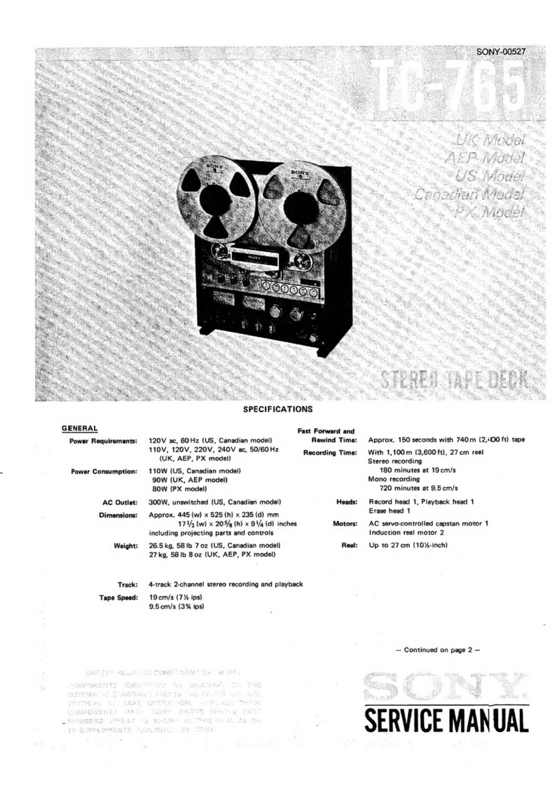
Sony TC-765 Setup guide

SON
Yo
STEREO
TAPE
DECK
_TC-765/766-2°
Owner’s
instruction
manual
Page
2
Before
operating
your
new
Sony
stereo
tape
deck,
please
read
this
manual
completely
to
become
familiar
with
all
its
features
and
capabilities.
Keep
this
manual
handy
for
future
reference.
Bedienungsanleitung
Seite
30
Bevor
Sie
Ihren
neuen
Sony
Stereo-Tape-Deck
in
Betrieb
nehmen,
lesen
Sie
bitte
diese
Bedienungsanleitung
volistandig
durch,
damit
Sie
mit
seinen
besonderen
Einrichtungen
und
Méglichkeiten
ver-
traut
werden.
;
Bewahren
Sie
diese
Anleitung
gut
auf,
spater
jederzeit
darin
nach-
schlagen
zu
kénnen.
©1977
by
Sony
Corporation

This
instruction
manual
covers
TC-765
(4-track
;19
cm/s,
7
1/2
ips)
-and
TC-766-2
(2-track
;
38
cm/s,
15
ips).
Where
difference
occurs
between
two
models,
it
is
clearly
de-
scribed
in
the
text.
:
FEATURES
@
Three
heads
and
three
motors
(TC-765)
@Four
heads
and
three
motors
(TC-766-2)
@Closed-loop/dual
capstan
tape
drive
@An
AC
servo-controlled
capstan
drive
motor
@
High-performance
F
&
F
(Ferrite
and
Ferrite)
heads
@
Separate
3-way
bias
and
equalization
selectors
@Logic-controlled
transport
function
buttons
@First
stage
of
the
amplifier
and
the
playback
head
are
directly
coupled.
WARNING
To
prevent
fire
or
shock
hazard,
do
not
expose
the
unit
to
rain
or
moisture.
To
avoid
electrical
shock,
do
not
open
the
cabinet.
Refer
servicing
to
qualified
personne!
only.
TABLE
OF
CONTENTS
Precautions
32
ac-d.0
Sas
Be
Saal
eS
ea
abodes
3
Operating
voltage...
1.
ens
3
Function
of
controls...
0.0...
ee
ee
es
4
Connections
.......0....
002.000
ee
eee
ra
hate
Be
OS
6
Jape:
threading...
.c2%s
soe
$1
etd,
Ga
et
he
AR
Ee
oe
7
Recording.........
a
AT
waka
dc
Sag
aan
a
aires
GN
a
ar
anaes
a>
He
7
Playback
25)
ee.05
°S.3atete,
Sle
Wie
eRie
eh
SN
eae
ae
eas
10
Erasing
is
e.g
5
fee
celeste
be
edo
weg
es
a
eaten
10
Timer-activated
recording
and
playback...............
10
Mic
and
line
mixing...
..........0000
ee
eee
"pagal
FI
Sound-on-Sound
recording
....
0...
00.000
cece
evens
11
ECho:-recording:
si
siao
3
ese
a
seh
oa
ivi
el
oa
Se
5
~.12
EGItin
gis
fn
Pets
toad
toe
ae
ref
teed,
Sete
y
eel
oes
we
as
12
Maintenance
......
0.0...
000
ee
ee
ee
ee
13
Specifications:
4.2.0
chsh
so
okls
kc
aa
be
wales
Bae
wwe
lee
Bs
14
Trouble:
checksis
ss.
s/s
ee
ee
hc
uieciand
H
RRA
hd
ee
ae
eae
15
FOR
THE
CUSTOMERS
IN
THE
UNITED
KINGDOM
—
WARNING
This
apparatus
must
be
earthed
at
the
terminals
in
your
3-pin
plug
as
follows:
IMPORTANT
The
wires
in
this
mains
lead
are
coloured
in
accordance
with
the
following
code:
Green-and-yellow:
Earth
(safety
earth)
Blue
:
Neutral
Brown:
Live
As
the
colours
of
the
wires
in
the
mains
lead
of
this
apparatus
..
may
not
correspond
with
the
coloured
markings
identifying
the
terminals
in
your
plug,
proceed
as
follows:
The
wire
which
is
coloured
green-and-yellow
must
be
connected
to
the
terminal
in
the
plug
which
is
marked
with
the
letter
E
or
by
the
safety
earth
symbol
~
or
coloured
green
or
green-and-yellow.
The
wire
which
is
coloured
blue
must
be
connected
to
the
termi-
nal
which
is
marked
with
the
letter
N
or
coloured
black.
The
wire
which
is
coloured
brown
must
be
connected
to
the
ter-
minal
which
is
marked
with
the
letter
L
or
coloured
red.

PRECAUTIONS
On
safety
;
@
Before
operating,
be
sure
the
operating
voltage
of
your
unit
is
identical
with
that
of
your
local
power
supply.
@Should
any
liquid
or
solid
object
fall
into
the
cabinet,
unplug
the
unit
and
have
it
checked
by
qualified
personnel
before
operating
it
any
further.
@
Unplug
the
unit
from
the
wall
outlet
if
it
is
not
to
be
used
for
an
extended
period
of
time.
To
disconnect
the
cord,
pull
it
out
by
the
plug.
Never
pull
the
cord
itself.
On
installation
@
Good
air
circulation
is
essential
to
prevent
internal
heat
build-up
in
the
unit.
Place
the
unit
in
a
location
with
adequate
air
circula-
tion.
@
Do
not
install
the
unit
in
a
location
near
heat
sources
such
as
radiators
or
air
ducts,
or
in
a
place
subject
to
direct
sunlight,
ex-
cessive
dust
or
mechanical
vibration.
;
On
head
cleaning
The
best
performance
of
your
unit
depends
on
the
periodic
clean-
ing
of
the
heads
and
all
surfaces
over
which
the
tape
travels.
Dirty
heads
and
tape
path
cause:
@Loss
of
high
frequency
response
@Loss
of
sound
volume
@
Sound
drop-out,
etc.
Cleaning
should
be
done
every
after
10
hours
of
operation.
For
details,
see
’
Maintenance”
:
Playback
waveform
at
10
kHz
With
a
clean
head
With
a
dirty
head
(The
output
level
fluctuates.)
Frequency
response
at
38
cm/s
(15
ips)
‘2
Saat
eal
as
Ts
With
a
clean
head
to)
~CL
With
a
dirty
head
[PTH
+
a
|
|
zs
3a
5
Tr
Ht
Ty
3
Even
hardly
visible
dust
layer
of
1,54
\
@
deteriorates
frequency
response.
\
=
10
t
roth
i
=
=
_o
-15
}.
4
J
100
1k
10k
Frequency
(Hz)
:
If
you
have
any
question
or
problem
with
your
unit,
please
contact
your
Sony
Service
Station
or
Sony
dealer.
OPERATING
VOLTAGE
Before
connecting
to
the
power
source,
check
that
the
voltage
selector
is
set
to
your
local
power
supply.
lf
itis
not
the
same,
change
the
voltage
selector
setting
as
fol-
lows
:
é
1.
Check
that
the
unit
is
disconnected
from
the
power
supply.
2.
Remove
the
cover
of
the
selector.
Loosen
the
arrow-marked
screw
on
the
cover
but
do
not
remove
it
from
the
cabinet.
Remove
the
other
screw.on
the
cover.
Then
turn
the
cover
around
the
arrow-marked
screw
so
that
you
can
unplug
the
selector.
“ey
3.
Pull
out
the
voltage
selector
plug
and
reinsert
it
so
that
the
top
arrow
mark
of
the
plug
points
to
the
proper
voltage
marking.
4.
After
changing
the
voltage,
reset
the
cover.
@Line
frequency
change
is
not
necessary
since
your
tape
deck
is
furnished
with
an
AC
servo-controiled
motor.
®
110V
220V
>
a>
240V
120V

FUNCTION
OF
contrdty
-
SONY
CLOSED
LOOP
BUAL
CAPSTAN
9:
@
Tension
arms/automatic
shut-off
switches
These
arms
maintain
uniform
tape
tension.
When
all
the
tapes
are
wound
and
these
arms
return
to
the
former
position,
tape
transport
mechanism
will
stop.
@
TIMER
switch
Usually
set
this
switch
to
OFF.
To
make
timer-activated
operation,
set
it
to
ON.
©
TAPE
SPEED
selector
19
cm
(7
1/2
ips):
For
high
quality
recording
9.5
cm
(3
3/4
ips)
:
For
longer
time
recording
38
cm
(15
ips):
For
studio
quality
professional
recording
19
cm
(7
1/2
ips)
:
For
longer
time
recording
Tape
speed
in
playback
should
be
the
same
as
that
in
recording.
@
REEL
SIZE
selector
:
Select
the
optimum
rewind
tension
and
reel
torque
for
the
reel
used:
The
“10”
position
is
for
10
1/2-inch
(27
cm)
reels,
and:
7”
is
for
7-inch
(18
cm)
or
5-inch
(13
cm)
reels.
©
POWER
switch
This
turns
the
power
on
or
off.
The
VU
meters
will
light
up
when
the
unit
is
turned
on.
©
VU
meters
With
MONITOR
switch
set
at
SOURCE,
the
meters
show
the
re-
cording
level
adjusted
by
the
REC
LEVEL
controls,
With
the
MONITOR
switch
set
at
TAPE,
the
meters
show
the
out-
put
level
adjusted
by
the
PB
LEVEL
controls.
0
VU
reading
corre-
sponds
to
0.435
V.
;
@
HEADPHONES
jack
=
Insert
low-impedance
headphones
to
monitor
the
input
and
re-
corded
signals.
@
MIC
jacks
Any
low-impedance
microphone
equipped
with
a
phone
plug
may
be
used.
If
your
microphone
is
equipped
with
a
mini
plug,
a
plug
adaptor
for
converting
to
phone
plug
is
required.

©
Mic
attenuator
switch
[MIC
ATT]
Usually
set
this
switch
at
the
“0”
position.
Mic
attenuator
is
useful
when
recording
a
large
input
signal
on
location
(rock
music,
etc.)
or
recording
with
a
microphone
too
close
to
the
source
without
overloading
the
tape
deck
amplifier.
When
the
needles
of
the
VU
meters
swing
over
the
0
VU
with
the
REC
LEVEL
MIC
controls
turned
down
on
the
scale
around
the
in-
dication
2-3,
first
set
the
MIC
ATT
switch
at
“15".
At
this
posi-
tion,
the
input
level
is
reduced
by
15
dB.
If
the
input
signal
level
is
still
large,
use
the
“30”
position.
At
this
position,
the
level
will
be
reduced
by
30
aB.
@
Tape
counter
and
reset
button
Use
the
counter
for
indexing
tape
contents.
Once
reels
are
thread-
ed,
set
the
counter
to
[0000]
by
pushing
the
reset
button.
The
figures
on
the
counter
change
as
the
tape
passes.
Make
a
note
of
the
figures
and
the
recorded
program
for
later
reference.
@
Function
buttons
@
Recording,
<<
Rewind,
Hi
Stop,
»
Forward
and
»
Fast-forward
tape
motion.
These
buttons
can
be
depressed
at
random
to
change
tape
motion
from
normal
to
fast
wind,
and
vice
versa
(Logic-controlled
transport
function).
[ll
Pause
button
To
momentarily
stop
during
recording
or
playback,
depress
this
button.
To
restart,
depress
it
again.
Also
use
this
button
for
smoother
start
of
recording.
®
Recording
level
controls
[REC
LEVEL-MIC,
LINE]
Adjust
the
recording
level
with
these
controls:
inner
knob
for
R
channel
and
outer
knob
for
L
channel.
Turn
down
the
unused
controls
full
to
“0”.
MIC:
When
recording
from
the
MIC
jacks
LINE
:
When
recording
from
the
REC/PB
and
LINE
IN
jacks
@®
MONITOR
switch
For
tape
playback,
set
the
switch
to
TAPE.
While
recording,
moni-
toring
of
input
sound
is
possible
with
this
switch
set
at
SOURCE,
and
monitoring
of
recorded
sounds
is
possible
with
this
switch
set
at
TAPE.
@®
Playback
level
controls
[PB
LEVEL]
These
controls
adjust
the
playback
signal
level
of
LINE
OUT
and
HEADPHONES
jacks.
Generally,
set
the
controls
at
center
posi-
tion.
For
further
information,
refer
to
page
9.
@®
Recording
mode
switches
[REC
MODE]
For
recording,
push
in
the
switches.
When
these
switches
are
pushed
in,
the
record
button
lamp
puts
on
and
off
repeatedly.
For
playback,
release
these
switches
to
prevent
inadvertent
erasure.
@
TAPE
SELECT
switches
BIAS
:
Select
the
optimum
bias
current
for
the
tape
to
be
used
in
recording
mode.
EQ:
Select
the
correct
equalization
characteristics
for
the
tape
to
be
used
in
recording
mode.
These
two
switches
nave
no
effect
on
playback.
@
2-track/4-track
selector
switch
Usually
set
this
switch
at
left
position
(2-track).
When
playing
back
the
tape
which
has
been
recorded
on
other
4-track
tape
deck,
_
Set
the
switch
at
right
position
(4-track).
If
2-track-recorded
tape
is
played
back
mistakenly
with
this
switch
set
at
right
position
(4-
track),
the
level
will
be
reduced.
On
the
other
hand,
if
4-track-
recorded
tape
is
played
back
with
this
switch
set
at-2-track
posi-
tion,
the
recorded
material
in
the
opposite
direction
will
be
played
back
mixedly.
4-track
Recording
monitor
muting
switch
(REC
MONITOR
MUTE}
(rear)
When
this
switch
is
set
to
ON,
the
line
outputs
are
cut
except
when
the
tape
is
played
back
with
the
MONITOR
switch
set
at
TAPE.
See
the
table
below.
This
switch
makes
the
microphone
recording
free
from
howling
effect
and
is
useful
for
instrumental
practice
whieh
necessitates
repetition
of
recording
and
playback.
MONITOR
switch
SOURCE
TAPE
During
recording
no
sound
no
sound
During
playback
no
sound
yes
Headphone
monitoring
is
free
from
this
switch.
REMOTE
CONTROL
connector
(rear)
Plug
the
Sony
Remote
Control
RM-30
(optional)
in
this
connector.
The
RM-30
features
“record
muting”*
as
well
as
remote
control
operation.
Read
the
RM-30
instruction
manual
before
operating
it
with
the
tape
deck.
*
A
device
which
is
beneficial
to
short-circuit
unwanted
program
sources
such
as
broadcasting
commercials,
thus
allowing
an
inter-
space
between
the
recordings.
INPUT
SELECT
switch
(rear)
When
recording
from
LINE
IN
jacks,
set
this
switch
at
LINE.
When
recording
from
REC/PB
connector,
set
this
switch
at
REC/PB.

CONNECTIONS
@
Turn
off
the
amplifier
before
making
connections.
@lnsert
the
cable
connectors
completely
into
jacks.
Loose
con-
nections
may
cause
hum
and
noise.
,
e@The
red
plug
of
the
supplied
connecting
cord
should
be
con-
nected
to
the
right
channel
and
the
gray
plug
to
the
left
channel.
Amplifier
connection
®
@REC/PBS
Cp
on
Connection
on
front
panel
REC/PB
(DIN)
connector
There
are
two
possibilities
of
the
amplifier
connection,
by
supplied
phono
(RCA)
connecting
cords
and
a
single
5-pin
DIN
connecting
cable.
Note
the
following
points.
@The
phono
cord
connections
are
recommended,
since
it
will
result
in
better
signal-to-noise
ratio.
For
playback
—-—Y.
{For
recording
“For
duplication
from
another
tape
deck
=.
signal
flow
=
e@Connect
the
tape
deck
to
an
AC
outlet
with
the
power
cord:
First
plug
the
cord
into
the
tape
deck
AC
IN
socket,
then
into
a
wall
outlet.
to
recording
outputs
to
tape
inputs
(or
auxiliary
inputs)
wma
tO
wall
outlet
to
line
to
line
:
inputs
outputs
Another
tape
deck
Amplifier
to
record/playback
connector
—_
e@Connection
between
amplifier
DIN
connector
and
phono
jacks
of
the
tape
deck
is
not
recommended,
since
their
input
and
output
sensitivity
and
impedance
are
not
correctly
matched.
@To
directly
connect
both
tape
deck
DIN
connectors,
a
DIN
cable
for
tape
duplication
is
required.
@When
recording
from
the
REC/PB
connector,
set
the
INPUT
—
SELECT
switch
located
in
the
rear
to
REC/PB
position,
andrecord-
ing
level
should
be
adjusted
with
the
REC
LEVEL
LINE
controls.

TAPE
THREADING
RECORDING
Set
the
REEL
SIZE
selector
according
to
the
reels
to
be
used.
Fundamental
steps
Use
the
same
size
reels
for
both
supply
and
take-up.
~
Check
the
INPUT
SELECT
switch:
1.
Secure
the
reels.
When
recording
from
LINE
IN
jacks
—
LINE
When
recording
from
REC/PB
connector
—
REC/PB
O
2.
Pass
the
tape.
3.
Wrap
the
tape
around
the
hub
of
the
right
reel
or
insert
the
end
of
the
tape
into
the
reel
slot.
4.
Rotate
the
reels
a
few
times
by
hand
until
there
is
no
Secx
in
the
tape.
If
there
is
slack,
tape
will
not
move
even
if
the
function
button
is
depressed.
QOQOOOO0O
Koo:
=|
eled
OOOH
oO
@
TIMER
switch
+
OFF
@
POWER
switch
>
Depress
to
ON.
©
Thread
a
tape.
@
Tape
counter
—>
Reset
to
[0000]
@
REEL
SIZE
selector
—
Set
to
the
reel
diameter
to
be
used.
@
TAPE
SPEED
selector
—
As
desired.
inOOO0O
SasoaS
<I
<
TAQ
a
For
the
supplied
27
cm
(10
1/2-inch)
metal
reel,
use
the
supplied
reel
adaptor
RAD-11
(reel
holder
and
spacer)
as
illustrated.
Spacer
Metal
reel
Ci
—~
Reel
holder
“fede
noe
@For
optional
plastic
reel,
neither
reel
holder
nor
spacer
is
re-
quired,
If
the
plastic
reel
has
a
large
center
hole,
use
the
reel
holder
only.
The
spacer
is
unnecessary.

Recording
After
the
fundamental
steps
@
to
@,
continue
with
the
following
steps
@
to
@.
@
TAPE
SELECT
switches
(both
BIAS
and
EQ)
—
Set
according
to
the
tape
used.
@
MONITOR
switch
—
SOURCE
@
PB
LEVEL
controls
—
Set
to
center
click
position.
@
Adjust
the
recording
level
with
respective
MIC
or
LINE
con-
,
trols
while
watching
the
VU
meters.
MIC
controls.
.
.
for
recording
from
MIC
jacks
LINE
controls.
.
.
for
recording
from
LINE
IN
jacks
or
REC/PB
con-
nector.
.
Be
sure
to
turn
the
unused
level
controls
full
counterclockwise.
@
REC
MODE
switches
—
Depress.
@
While
depressing
the
@
button,
depress
the
>
button,
Now
recording
starts.
@
When
recording
completes,
depress
the
Jf
button.
Tape
BIAS/EQ
recommendations
The
following
list
shows
our
recommended
settings,
which
have
been
determined
through
critical
listening
tests
and
electrical
characteristic
measurements
on
commercially
available
tapes.
The
setting
could
be
changed
to
your
preference.
For
Sony
tapes,
be
sure
to
use
the
recommended
settings
to
obtain
the
optimum
tape
characteristics.
NORMAL
SPECIAL
Fe-Cr
BASF
LH,
LHS
|
SCOTCH
#211,
~
SONY
PR
AGFA
PE,
PEM
#212,
#213:
MEMOREX
AMPEX
406,
407.
SONY
SLH
SONY
Ferri-Chrome
MED
|
SCOTCH
#218
|
SCOTCH
CLASSIC
|
SCOTCH
#206,
#207
TDK
AUDUA
waxcch-Up
|
HIGH
SCOTCH
#250
Po
Record
monitoring
As
this
tape
deck
has
separate
record
and
playback
heads,
instan-
taneous
tape-source
comparison
is
possible
with
the
MONITOR
switch.
SOURCE
:
Source
sound
is
heard
TAPE
:
Recorded
sound
is
heard
@ln
microphone
recording,
if
monitoring
through
the
speakers,
howling
effect
may
occur.
Use
of
the
REC
MONITOR
MUTE
switch
avoids
this
howling
effect
and
monitoring
may
be
done
through’
headphones.
@if
the
amplifier
has
a
tape-monitor
selector
and
if
connection
is
made
through
tape
deck
LINE
IN
and
LINE
OUT
jacks,
source/tape
comparison
is
possible
with
the
amplifier
monitor
selector.
In
this
case,
the
tape
deck
MONITOR
switch
should
be
set
at
TAPE.
SOURCE
MONITOR
Recording
me
+
‘esa
outputs
:
Amplifier
ape
inputs
i
|
:
!
LINE
IN
Tape
deck
LINE
OUT
REC
LEVEL
)
(
SOURCE
MONITOR
Erase
head
*
Record
head
Tape
immammmenmage”
Playback
head

PB
LEVEL
controls
These
controls
adjust
the
playback
signal
level
at
the
LINE
OUT
and
HEADPHONES
jacks.
The
adjusted
level
is
indicated
on
the
VU
meters,
with
a
O
VU
reading
corresponding
to
0.435
V
output,
which
appears
when
the
control
is
halfway
up
(with
the
indicator
at
“5").
Full
clockwise
rotation
of
the
PB
LEVEL
control
beyond
midpoint
will
provide
a
5
dB
boost,
and
full
counterclockwise
rota-
tion
will
bring
the
volume
down
to
zero.
Generally,
set
these
con-
trols
at
center
position.
The
usages
are
as
follows.
During
record
monitoring,
the
setting
of
these
controls
at
center
position
provides
nearly
equal
levels
on
both
SOURCE
and
TAPE
positions
of
the
MONITOR
switch.
During
playback,
adjust
the
tape
deck.to
match
other
sources:.
If
the
tape
deck
playback
level
differs
from
that
of
other
sources
connected
to
the
amplifier,
such
as
a
tuner,
record
player
etc.,
the
sound
may
become
suddenly
louder
or
softer
when
the
amplifier
input
selector
is
switched
back
and
forth
between
tape
and
some
other
source.
During
duplication
on
another
tape
deck,
adjust
these
controls
so
that
the
sound
is
not
distorted.
Recording
a
new
material
while
the
tape
is
in
motion
This
tape
deck
may
directly
go
from
play
to
record
while
the
tape
is
in
motion.
1.
Perform
the
necessary
steps
for
recording.
2.
Depress
the
REC
MODE
switches.
The
@
button
blinks.
3.
Depress
the
®
button
and
listen
to
the
playback
sound.
4,
At
the
point
where
new
material
is
to
be
recorded,
depress
the
@
and
»
buttons
simultaneously.
The
@
button
illumination
changes
to
a
steady
red
light.
At
this
moment,
recording
begins.
Recording
level
adjustment
Tape
saturation
levels
differ
between
the
types
of
tape.
Recording
level
should
be
adjusted
according
to
the
tape
to
be
used
in
order
to
utilize
it
to
the
utmost
permissible
level.
This
is
the
knack
not
only
for
deriving
the
possible
characteristics
from
the
tape
but
also
assuring
good
recording
result.
High
recording
level
is
recommended
to
reduce
annoying
tape
noise,
but
overloaded
and
distorted
tape
could
result
if
the
level
is
too
high.
When
using
a
Sony
SLH
tape,
for
example:
Adjust
the
recording
level
so
that
the
needles
of
the
VU
meters
swing
around
the
O
VU
reading
and
sometimes
swing
within
red
zone.
Continuous
deflection
within
red
zone
will
lead
to
distor-
tion.
On
the
other
hand,
as
for
TC-766-2,
when
recording
at
38
cm/s
(15
ips),
staying
of
the
needies
within
red
zone
is
still
tolera-
ble,
so
make
the
needles
swing
around
+3
VU
and
even
go
over
the
scale
for
an
instance
at
the
sudden
high
level
burst,
as
the
dynamic
range
becomes
wider
than
that
of
19
cm/s
(7
1/2
ips).
=10
.
=
+
oe,
oe
oe
3
3
0
+3
ae
;
en
oe
oe
,
i
Too
low
level
Too
high
level
Proper
level
Proper
level
at
(S/N
ratio
will
(Sound
will
be
38cm/s
with
be
poor.)
distorted.)
TC-766-2
But
be
cautious
with
peaks
of
short
duration
out
of
a
relatively
low
recording
level
;
as
the
needles
of
the
VU
meters
cannot
follow
them
because
of
their
inertia,
they
will
show
levels
much
smatler
than
the
actual
levels
(up
to
12
or
14
dB).
Recording
of
FM
broadcasts
or
discs
is
relatively
simple
because
broadcast
stations
and
disc
companies
use
standardized
limiters
to
reduce
the
dynamic
range
of
the
original
sound
source.
More
care
has
to
be
taken
in
case
of
live
recordings.
The
dynamic
range
is
undiminished
by
any
limiter,
and
a
small
movement
may
change
the
distance
between
sound
source
and
microphone,
thus
changing
the
signal
level
even
when
repeating
an
identical
pas-
sage.
Above
all
consideration
has
to
be
given
to
the
fact
that
tape
saturation
and
distortion
at
higher
frequencies
occur
at
lower
levels,
which
may
be
especially
troublesome
in
case
of
piano
re-
cordings,
etc.
To
make
things
even
more
complicated,
microphone
amplifiers
may
overload.
Using
the
MIC
ATT
switch
is
an
effective
method.
In
any
way,
having
acquired
a
little
bit
of
experience,
you
will
be
quite
successful.
Do
not
change
the
recording
level
once
the
recording
starts,
as
this
will
easily
be
audible
during
playback,
especially
when
the
stereo
balance
is
changed.
If
adjustment
becomes
necessary,
it
is
advisable
to
wait
until
a
break
or
a
pause
between
movements
oc-
curs
or
a
soloist
has
finished
his
turn.

PLAYBACK
For
TC-766-2,
check
the
2-track/4-track
selector
switch.
When
playing
back
a
2-track-recorded,
tape
>
left
(2-track)
When
playing
back
a
4-track-recorded
tape
—
right
(4-track)
@
TIMER
switch
—
OFF
@
POWER
switch
—
Depress
to
ON.
@
Thread
a
tape.
@
Tape
counter
—
Reset
to
[0000].
@
REEL
SIZE
selector
—
Set
to
the
reel
diameter
to
be
used.
@
TAPE
SPEED
selector
—
Set
according
to
the
speed
when
re-
corded.
@
MONITOR
switch
—
TAPE
©
Depress
the
»
button.
Now
playback
starts.
@
When
playback
completes,
depress
the
lf
button.
@In
playback,
TAPE
SELECT
switches
have
no
effect.
ERASING
When
the
tape
deck
functions
in
record
mode,
the
erase
head
operates
and
any
previous
material
is
erased
automatically.
To
erase
the
recorded
contents
without
recording:
@Turn
the
REC
LEVEL
controls
(both
MIC
and
LINE)
full
counter-
clockwise
to
“O”.
@
Set
the
BIAS
switch
at
the
position
appointed
in
page
8,
or
at
the
HIGH
position
And
start
the
tape
deck
in
record
mode.
;
@For
quick
erasure,
use
a
commercially
available
eraser.
10
TIMER-ACTIVATED
RECORDING
AND
PLAYBACK
Automatic
recording
and
playback
at
any
desired
time
is
possible
using
a
commercially
availabie
timer.
Continual
operation
may
be
accomplished
with
a
timer
designed
to
turn
the
tape
deck
on
and
off
any
number
of
times.
Recording
1.
Set
the
tape
deck
TIMER
switch
to
OFF.
2.
Connect
the
tape
deck
power
cord
to
the
timer
which
has
been
set
for
the
desired
time.
,
3.
Perform
the
necessary
steps
for
recording.
(Be
careful
not
to
depress
the
@
and
>
buttons.)
4.
Set
the
tape
deck
TIMER
switch
to
ON.
The
tape
deck
is
now
ready
for
automatic
start
of
recording
at
the
timer-set
time.
.
Playback
F
Procedure
is
almost
the
same
as
that
of
recording.
@Be
careful
not
to
depress
the
REC
MODE
switches.
@Be
sure
to
set
the
MONITOR
switch
to
TAPE.
NOTE
@Read
the
instruction
manual
of
the
timer
carefully
before
using
it.

MIC-AND-LINE
MIXING
Connect
microphones
to
MIC
jacks
and
line
source
to
LINE
IN
jacks.
While
listening
through
headphones,
adjust
the
mixing
level
by
turning
the
respective
controls
of
MIC-L,
R,
LINE-L,
R.
The
VU
meters
indicate
the
composite
recording
level
of
mic
and
line
_
inputs.
MIC-
REC
LEVEL-
LINE
SOUND-ON-SOUND
RECORDING
While
playing
back
the
basic
program
monophonically
recorded
in
one
channel,
add
a
new
program
from
a
microphone
and
record
the
two
programs
in
the
other
channel.
This
enables
you
to
record
a
duet
by
yourself
or
create
other
special
effects.
Sound-on-Sound
recording
on
the
right
channel
(L
>
R)
1,
Record
the
basic
program
on
the
left
channel
and
rewind
the
tape.
2.
Connect
the
L
LINE
OUT
jack
and
R
LINE
IN
jack
by
using
the
supplied
connecting
cord.
Be
sure
to
use
the
plugs
of
the
same
color
at
both
ends
of
the
connecting
cord.
3.
Connect
a
microphone
into
the
R
MIC
jack.
4.
Connect
the
headphones.
:
5.
Push
the
R
REC
MODE
switch.
6.
Set
the
MONITOR
switch
to
TAPE.
7.
Adjust
the
recording
level.
@)
Temporarily
set
the
R
LINE
and
R
MIC
controls
to
the
indi-
cation
“5”,
:
@
Turn
the
R
PB
LEVEL
control
full
counterclockwise
and
set
the
L
PB
LEVEL
control
to
the
indication
“5”.
Depress
the
@
and
»
buttons.
Sing
to
a
microphone
while
listening
to
the
basic
program
through
left
headphone.
@
Rewind
the
tape.
Turn
down
the
L
PB
LEVEL
control
full
counterclockwise
and
turn
up
the
R
PB
LEVEL
control
to
the
indication
“5”,
Depress
the
®
button
and
monitor
the
mixed
sounds
through
right
headphone.
(Recording
level
is
indicated
in
the
R
VU
meter.)
@
Readjust
the
recording
level
as
follows:
@To
increase
the
whole
recording
level,
turn
the
R
LINE
con-
trol
clockwise
beyond
the
indication
“5”,
and
to
decrease,
turn
it
down.
@To
increase
the
mic
sound
against
the
basic
program,
turn
the
R
MIC
control
clockwise
beyond
the
indication
“5”
and
to
decrease,
turn
it
down.
8.
Now
Sound-on-Sound
recording
is
prepared.
Rewind
the
tape.
9.
Turn
down
the
R
PB
LEVEL
control
full,
set
the
L
PB
LEVEL
con-
trol
to
“5”,
and
depress
the
@
and
»®
buttons.
Sing
to
the
micro-
phone.
:
@To
listen
to
the
composite
recording,
turn
down
the
L
PB
LEVEL
control
and
turn
up
the
R
PB
LEVEL,
then
play
back
the
tape.
@If
you
are
not
content
with
the
result,
repeat
these
steps
as
you
like
because
the
basic
program
is
left
recorded.
@For
recording
on
the
ieft
channel
(R
—
L),
you
have
only
to
con-
vert
the
R
and
L
channels
in
the
above
mentioned
steps.
gy:
LINE
OUT
(L)
LINE
IN
(R)
Record
head
Playba
LINE
OUT
(L)
LINE
IN
(R)
11
‘
i
H

ECHO
RECORDING
Recorded
sound
is
caught
by
the
playback
head,
and
recorded
again
in
the
same
track
through
line
input.
The
distance
between
record
head
and
playback
head
causes
the
resonant
effect
like
an
echo.
Stereo
echo
1.
Insert
twe
microphones
into
MIC
jacks.
2.
Turn
the
L
LINE,
R
LINE,
L
MIC
and
R
MIC
controls
full
counter-
clockwise.
3.
Connect
the
LINE
!N
jacks
and
LINE
OUT
jacks
by
using
the
supplied
connecting
cord
matching
the
channels
R
to
R,
and
L
to
L.
4.
Connect
the
headphones.
5.
Set the
MONITOR
switch
to
TAPE.
’
6.
Push
the
REC
MODE
switches
and
depress
the
@
and
»
buttons.
7.
While
listening
through
the
headphones,
adjust
the
L
and
R
MIC
controls..
Then
slowly
turn
the
L
and
R
LINE
controls
clock-
wise
for
desired
echo.
Be
careful
not
to
excessively
increase
the
recording
level.
Otherwise
oscillation
may
occur
as
a
rumbling
sound.
‘
Now,
echo
recording
preparation
is
complete.
Rewind
the
tape
to
_the
beginning
and
start
a
formal
recording.
In
this
case,
discon-
nect
the
stereo
headphones,
since
headphone
monitoring
may
disturb
your
tempo
because
of
the
time-lag
between
original
sound
and
headphone
sound.
.
@For
mono
echo
recording,
use
the
desired
L
or
R
channel
only.
The
illustration
shows
mono
recording.
©
LINE
OUT
(L)
°
LINE
IN
(L)
a
12
‘EDITING
There
are.two
ways
of
tape
editing:
editing
by
tape
duplication
and
splicing.
Before
editing,
play
the
original
tape
thoroughly,
and
note
the
tape
counter
number
where
the
unwanted
sounds
(narra-
ration
or
commercials,
pop
noise,
etc.)
are
located..
Then
go
back
-and
proceed
with
editing
in
either
way.
Editing
by
duplication
For
connection,
see
page
6.
lf
one
tape
deck
is
inferior
to
the
other
in
quality,
use
the
better
one
as
a
master
tape
deck
for
the
playback
process
to
obtain
bet-
ter
S/N.
Editing
by
splicing
As
the
tape
will
be
cut
and
spliced,
recorded
materials
in
opposite
direction
will
also
be
cut
off.
If
necessary,
duplicate
the
tape
to
another
tape
before
proceeding.
Cueing
1.
Stop
the
tape
with
the
pause
button
in
playback
mode
at
the
portion
to
be
spliced.
2.
Move
the
tape
across
the
playback
head
back
and
forth
by
turn-
ing
both
reels
by
hand.
3.
While
listening
to
cue
sound,
find
the
correct
portion
to
be
spliced,
and
carefully
mark
it
at
the
position
of
the
playback
head
on
the
outer
side
of
the
tape
with
soft
colored
pencil.
Yellow
will
be
most
distinctive.
Note:
Take
care
not
to
get
excessive
marking
material
on
the
heads.
Any
stain
on
the
heads
will
cause
contamination
and
im-
pair
tape-and-head
contact.
Splicing
Use
splicing
tape
and
a
demagnetized
pair
of
scissors.
1.
Neatly
overlap
the
tapes
to
be
spliced
and
cut
diagonally.
2.
Place
the
two
diagonal
tape
ends
together,
outer
side
up,
on
a
flat
surface.
Be
careful
to
make
ends
meet
but
not
overlap.
,
3.
Apply
a
piece
of
splicing
tape
diagonally
over
the
aligned
ends,
and
press
it
firmly.
4.
Trim
off
the
excessive
splicing
tape,
slightly
cutting
into
the
tape.
Playback
head

NOTE
@Do
not
use
ordinary
cellophane
tape
as
it
tends
to
spoil
record-
ing
tapes.
Also
avoid
using
magnetized
scissors
or
razor
blades.
Magnetized
instruments
will
cause
a
“click”
or
“pop”
at
the
spliced
portion.
@
Take
care
not
to
unnecessarily
touch
the
tape.
Even
unvisible
traces
of
grease
and
sweat
from
your
fingers
will
hinder
a
good
sticking.
Searching
the
program
beginning
in
rewind
or
fast-forward
mode
;
While
the
tape
is
fast-winding,
depress
the
pause
button,
then
slightly
push
up
the
left
and
right
pinch
rollers
against
the
heads.
Chattering
sounds
will
be
heard
from
the
recorded
part
of
the
tape.
Search
the
blank
portion
between
these
sounds.
The
sound
volume
may
be
changed
according
to
the
pressure
ap-
plied
to
the
pinch
rollers
by
your
fingers.
@Don’t
push
the
pinch
rollers
excessively.
Too
much
pressure
will
deteriorate
or
even
cut
the
tape.
MAINTENANCE
Cleaning
of
heads
and
tape
path
Generally
cleaning
after
every
10
hours
of
operation
will
be
suf-
ficient.
However
all
surfaces
over
which
tape
travels
should
be
cleaned
before
making
high
quality
recordings.
Take
the
supplied
head
cleaning
pen
and
wipe
the
heads
and
tape
path.
For
easier
cleaning
of
pinch
roller
and
capstan,
rotate
them
by
holding
the
automatic
shut-off
switch
and
the
tape
guide
with
a
rubber
band.
Supply
the
power
to
the
unit
and
depress
the
»
button.
Erase
head
Record
head
Playback
head
Capstan
Pinch
roller
Tape
guide:
Tension
arm/automatic
shut-off
switch
———!
Tension
roller
Record
head
Playback
head
(2-track)
Playback
head
(4-track)
TC-766-2
Erare
head
Capstan
Pinch
roller
Tape
guide
Tension
arm/automatic
shut-off
switch
———_~
Tension
roller
Rubber
band
Demagnetizing
heads
Residual
magnetism
will
gradually
build
up
on
the
heads
through
continuous
use
and
cause
erasure
of
high
frequencies
and
hiss
build-up.
The
heads
and
metallic
parts
of
the
tape
path
should
be
demagnetized
after
20-30
hours
of
operation
with
a
commercially
available
head
demagnetizer.
Be
sure
the
unit
is
turned
off.
Cleaning
cabinet
Clean
the
cabinet,
panel
and
controls
with
a
soft
cloth
lightly
moisténed
with
mild
soap
solution.
Do
not
use
any
type
of
scour-
ing
powder
or
solvent
such
as
alcohol
or
benzine.
Inside
check
Consult
your
nearest
Sony
Service
Station
or
Sony
dealer
once
a
year
to
maintain
optimum
performance.
13

SPECIFICATIONS.
Power
requirements
Power
consumption
Semiconductors
Tape
speeds
Recording
time
Fast
winding
time
Reel
Track
system
Heads
Motors
Bias
frequency
Equalization
Signal-to-noise
ratio
110,
120,
220
or
240
V
AC
(adjustable)
50/60
Hz
90
W
2
ICs,
3
FETs,
104
transistors
89
diodes
19
cm/s
(7
1/2
ips)
9.5
cm/s
(3
3/4
ips)
With
1100
m
(3,600
ft)
tape,
27
cm
reel
Stereo
recording
180
minutes
at19
cm/s
©
Mono
recording
720
minutes
at
9.5
cm/s
Approx.
150
sec.
with
740
m
(2400
ft)
tape
up
to
27
cm
(10
1/2-inch)
4-track
2-channel
stereo
Record
head
1,
Playback
head
1
Erase
head
1
AC
servo-controlled
capstan
motor
1
induction
reel
motor
2
,
160
kHz
JIS
standard
19
cm/s
:3,180
us
+
50
us
9.5
cm/s:
3,180
us
+
90
us
With
Sony
Ferri-Chrome
Tape
61
dB
(DIN,
1975
rev.)
56
dB
(DIN
old)
Total
harmonic
distortion
Frequency
response
Wow
and
flutter
Inputs
Outputs
0.7%
:
With
Sony
Ferri-Chrome
Tape
and
SLH
Tape
30-25,000
Hz
+
3
dB
at
19
cm/s
30-18,000
Hz
+
3
dB
at
9.5
cm/s
With
regular
tape
30-18,000
Hz
+
3
dB
at
19
cm/s
30-15,000
Hz
+
3
dB
at
9.5
cm/s
+0.07%
at
19
cm/s
+0.15%
at
9.5
cm/s
Microphone
input
(phone
jack)...
...
sensitivity
0.2
mV
(—72
dB)
for
low
impedance
microphone
Line
input
(phono
jack)...........
sensitivity
0.06
V
(—22
dB)
input
impedance
100
k
ohms
Line
output
(phono
jack)..........
output
level
0.435
V
(—5
dB)
at
load
impedance
of
100
k
ohms,
with
PB
LEVEL
controls
set
to
center
detent
position,
with
PB
LEVEL
controls
set
to
“10”
0.775
V
(O
cB)
Suitable
load
impedance
more
than
10k
ohms
Headphone
output..............
for
low
impedance
headphones
Record/playback
(DIN)
connector
Other
jack
Dimensions
Weight
14
Input
impedance
less
than
10
k
ohms
Output
impedance
less
than
10
k
ohms
11-pin
remote
control
connector
Approx.
445
x
525
x
235
mm
(w/h/d)
(17
1/2
x
20
5/g
x
9
1/4
inches)
Including
projecting
parts
and
controls
Approx.
27
kg
(59
Ib
8
oz)
Supplied
accessories
Power
requirements
Power
consumption
Semiconductors
Tape
speeds
Recording
time
Fast
winding
time
Reel
Track
system
Heads
Motors
Bias
frequency
Equalization
Signal-to-noise
ratio
Reel
adaptor
and
spacer
RAD-11....
.
Reel:
R-WA.
de
a
ee
ee
Connecting
cord
RK-74H
.........
Head
cleaningpen
.............
110,
120,
220
or
240
V
AC
(adjustable)
50/60
Hz
90
W
2
ICs,
3
FETs,
103
transistors
86
diodes
38
cm/s
(15
ips)
19
cm/s
(7
1/2
ips)
With
1,100
m
(3,600
ft),
27
cm
reel
Stereo
recording
45
minutes
at
38
cm/s
Mono
recording
180
minutes
at
19
cm/s
Approx.
150
sec.
with
740
m
(2,400
ft)
tape
;
up
to
27
cm
(10
1/9-inch)
2-track
2-channel
stereo
recording
and
playback
4
track
2-channel
stereo
playback
Record
head
1,
Playback
head
2
Erase
head
1
AC
servo-controlled
capstan
motor
1
Induction
reel
motor
2
160
kHz
JIS
standard
3,180
ps
+
50
ps
With
Sony
Ferri-Chrome
Tape
64
dB
(DIN,
1975
rev.)
59 dB
(DIN,
old)
Total
harmonic
distortion
Frequency
response
Wow
and
flutter
Inputs
Outputs
0.5%
With
Sony
Ferri-Chrome
Tape
and
SLH
’
Tape
30-30,000
Hz
+
3dB
at
38
cm/s
30-25,000
Hz
+
3
dB
at
19
cm/s
With
regular
Tape
30-22,000
Hz
+
3
dB
at
38
cm/s
30-18,000
Hz
+
3
dB
at
19
cm/s
+0.035%
at
38
cm/s
+0.07%
at
19
cm/s
Microphone
input
(phone
jack)......
sensitivity
0.2
mV
(—72
dB)
for
low
impedance
microphone
Line
input
(phono
jack})...........-
sensitivity
0.06
V
(—22
dB)
input
impedance
100
k
ohms
Line
output
(phono
jack)..........
output
level
0.435
V
(—5
dB)
at
load
impedance
of
100
k
ohms,
with
PB
LEVEL
controls
set
to
center
detent
position,
with
PB
LEVEL
controls
set
to
|
“10”
0.775
V
(0
dB)
Suitable
load
impedance
more
than
10k
ohms
:
:
Headphone
output
.....
Site
at
aa
&
4
for
low
impedance
headphones
Record/playback
(DIN)
connector
Other
jack
Input
impedance
less
than
10
k
ohms
Output
impedance
less
than
10
k
ohms
11-pin
remote
control
connector

Dimensions
Approx.
445
x
525
x
235
mm
(w/h/d)
(17
1/2
x
20
5/g
x
9
1/4
inches)
Including
projecting
parts
and
controls
Weight
Approx.
27
kg
(59
Ib
8
oz)
Supplied
accessories
Ree!
adaptor
and
spacer
RAD-11......
2
Reel
R-11A
1.2.0...
.--...004.
21
Connecting
cord
RK-74H
.........
2
Head
cleaning
pen
.............
1
While
the
information
given
is
correct
at
the
time
of
printing,
“small
production
changes
in
the
course
of
our
company’s
policy
of
improvement
through
reserch
and
design
might
not
necessarily
be
indicated
in
the
specifications.
We
please
ask
you
to
check
-with
your
appointed
Sony
dealer
if
clarification
on
any
point
is
required.
TROUBLE
CHECKS
The
following
chart
will
help
correct
most
problem
which
may
.
occur
with
the
unit.
Before
going
through
the
check
list
below,
first
pay
attention
to
the
following
fundamental
points.
@The
power
cord
must
be
connected
firmly.
@Connection
to
the
amplifier
must
also
be
firm.
@
Heads,
capstan
and
pinch
roller
should
be
cleaned.
@
The
amplifier
controls
and
switches
should
be
set
correctly.
Tape
does
not
move
even
when
function
buttons
are
de-
pressed.
@
There
is
slack
in
the
tape.
Tape
does
not
run
even
when
the
»
button
is
depressed.
_
@The
pause
button
is
depressed.
When
power
is
supplied,
tape
runs
even
though
the
»
button
is
not
depressed.
@
The
TIMER
switch
is
set
to
ON.
:
Recording
source
cannot
be
monitored
in
the
playback
mode,
when
setting
the
MONITOR
switch
to
SOURCE.
@The
REC
MONITOR
MUTE
switch
is
set
to
ON.
During
recording,
there
is
a
great
volume
difference
between
SOURCE
and
TAPE
settings
of
the
MONITOR
switch.
@The
PB
LEVEL
controls
are
set
far
beyond
midpoint.
Unclear
or
distorted
recording
or
excessive
wow
and
flutter
@Contamination
of
the
heads.
Poor
S/N
ratio
during
recording
@The
REC
LEVEL
controls
unused
(MIC
or
LINE)
should
be
turned
full
counterclockwise.
Recording
cannot
be
made.
@The
REC
MODE
switches
are
not
depressed.
@Check
the
INPUT
SELECT
switch.
No
playback
or
decrease
of
sound
reproduction
@Contamination
of
the
playback
head.
@The
MONITOR
switch
should
be
set
to
TAPE.
At
SOURCE
posi-
tion,
no
sound
is
heard.
@Check
the
amplifier
volume
controls.
@Check
the
amplifier
input
selector.
@Check
if
the
PB
LEVEL
controls
are
set
to
“0”.
@Check
the
2-track/4-track
selector
switch.
(TC-766-2)
Too
low
microphone
sound
@Set
the
MIC
ATT
switch
at
“0”.
@
Use
low
impedance
microphones.
No
sound
from
the
headphones
@Check
the
PB
LEVEL
controls.
Insufficient
erasure
e@Contamination
of
the
erase
head
Oscillation
occurs
when
trying
to
record
from
the
amplifier
@lf
the
LINE
OUT
jacks
of
the
tape
deck
are
connected
to
the
am-
plifier
AUX
jacks
and
if
these
are
switched
on,
change
the
amplifier
input
selector
to
another
position.
15

Diese
Bedienungsanleitung
gilt
fir
das
Modell
TC-765
(4-Spur,
19
cm/s)
und
das
TC-766-2
(2-Spur,
38
cm/s).
Die
Unterschiede
zwischen
den
zwei
Modellen
werden
genau
im
Text
behandelt.
BESONDERE
MERKMALE
@
Drei
Tonképfe
und
drei
Motoren
(TC-765)
e@
Vier
Tonképfe
und
drei
Motoren
(TC-766-2)
@Geschlossener
Zwei-Andruckrollenbetrieb
@
Servogesteuerter
Wechselstrommotor
fir
die
Bandantriebswelle
@F
&
F
(Ferrit
und
Ferrit)-Hochleistungstonkdépfe
e@Getrennte
3-Weg-Wahler
fir
Vormagnetisierung
und
Entzer-
rung
;
@Logische
Kontrolle
der
Funktionstasten
@Die
erste
Stufe
des
Verstaérkers
und
der
Wiedergabekopf
sind
direkt
gekoppelt.
VORSICHT
Um
einen
elektrischen
Schlag
oder
Brandgefahr
zu
vermeiden,
setzen
Sie
das
Gerat
weder
Regen
noch
Feuchtigkeit
aus.
Um
einen
elektrischen
Schlag
zu
vermeiden,
darf
das
Gehause
nicht
gedéffnet
werden.
Uberlassen
Sie
Wartungsarbeiten
nur
qualifiziertem
Personal.
30
INHALTSVERZEICHNIS
Zur
besonderen
Beachtung...........
000
eee
eee
31
Betriebsspannung.....
0.0.0.2
ee
eee
ees
31
Funktion
der
Bedienungselemente
..............2005
32
SWANSCHIGSSES
6
5
wi
d.0g
te
eutibie
oe
Gage
date
ed
yes
34
Einfadeln
des
Tonbandes
..........
0000
e
eee
eee
34
Autnahmes,.
#:.204:%
-a-e
eeete
Seed
ave
Lae
ee
ede
35
Wiedergabe
s.
3:3
sss.
ie
Gie
Seine
8
AS
ee
we
aS
hae
38
LOSCheN
t.:25..a0n
sacs
ste
Ge
a
tiaes
Held
eed
a
ahs
38
Zeitgesteuerte
Aufnahme
und
Wiedergabe.............
38
Mischen
von
Mikrofon-
und
Direkteingangssignalen.......
39
7
Sound-on-Sound’”-Aufnahme..
2.
ee
39
EGHO=AUf
nal
ine
fitz
on
asec
05s
Sechelt
ett
40
Bandmontage®
6.276.
od
pik
es
ees
Os
ne
RR
40
Wartung
und
Pflege
2.2.0...
0...
ee
eee
eee
41
Technische
Daten...
..
2.2...
0.00.
2
eee
eee
es
42
Stérungsiiberprifungen
..
2...
0.0...
ee
ee
43

ZUR
BESONDEREN
BEACHTUNG
Zur
Sicherheit
e@Vergewissern
Sie
sich,
ob
die
Betriebsspannung
Ihres
Gerates
mit der
drtlichen
Netzspannung
iibereinstimmt.
@Falls
irgendeine
Flissigkeit
oder
ein
Fremdkorper
in
das
Ge-
hause
gelangt,
ziehen
Sie
den
Netzstecker
und
lassen
Sie
das
Gerat
von
einem
Fachmann
Uberpriifen,
bevor
Sie
es
weiter
be-
nutzen.
@Ziehen
Sie
den
Netzstecker
aus
der
Steckdose,
wenn
Sie
das
Gerat
Uber
langere
Zeit
nicht
benutzen.
Um
das
Netzkabel
heraus-
,zuziehen,
fassen
Sie
es
immer
am
Stecker
an;
ziehen
Sie
niemals
am
Kabel.
Zur
Aufstellung
*
@Gute
Luftzirkulation
ist
wesentlich,
um
einen
Warmestau
im
Ge-
rateinneren
zu
verhindern.
Steilen
Sie
das
Gerat
daher
so
auf,
daB
es
von
gentgend
Luft
durchstrémt
werden
kann.
:
@
Stellen
Sie
das
Gerat
nicht
neben
Heizkérpern
und
Warmluftaus-
lassen
auf,
oder
dort,
wo
es
direktem
Sonnenlicht
ausgesetzt
ist,
und
schiitzen
Sie
es
vor
Staub
und
Erschiitterungen.
.
Zur
Tonkopfreinigung
Die
optimale
Leistung
Ihres
Tonbandgerates
hangt
davon
ab,
daB
Sie
die
Tonképfe
und
alle
Oberflachen,
Gber
die
das
Tonband
lauft,
periodisch
reinigen.
Schmutz
auf
Tonképfen
und
Bandfiihrung
verursacht
:
@Verlust
in
der
Wiedergabe
hoher
Frequenzen
@Verlust
in
der
Lautstarke
@
Klanglécher
(drop-out)
usw.
Eine
Reinigung
sollte
jeweils
nach
10
Betriebsstunden
durchge-
fihrt
werden.
Fir
Einzelheiten,
siehe
,,Wartung
und
Pflege”.
Wiedergabe-Signal
bei
10
kHz
Mit
einem
sauberen
Tonkopf
Mit
einem
schmut-
zigen
Tonkopf
(Der
Ausgangspegel
schwankt.)
Frequenzgang
bei
38
cm/s
T
TT
it
einem
o
=
®
-5
oOo
2
i
a
Selbst
eine
kaum
sichtbare
Staubdicht
von
@
_10
1,5
«
verursacht
diese
Verschlechterung
g
des
Frequenzgangs.
<
-15
sak
ees
oe
_
100
10k
1k
Frequenz
(Hz)
‘Sollten
Fragen
oder
Probleme
mit
dem
Gerat
auftreten,
wenden
Sie
sich
bitte
an
die
nachste
Sony
Kundendienststelle
oder
Ihren
-nachsten
Sony
Handler.
BETRIEBSSPANNUNG
Vor
dem
Anschlu8
an
des
Lichtnetz
vergewissern
Sie
sich,
da8
der
Spannungswéahler
richtig
auf
ihre
drtliche
Netzspannung
‘einge-
stellt
ist.
Wenn
die
Voltzahl
nicht
ibereinstimmt,
stellen
Sie
den
Wahler
wie
folgt
um.
1.
Ziehen
Sie
das
Netzkabel
aus
der
Steckdose.
2.Nehmen
Sie
den
Deckel
des
Wa&hlers
ab:
Lockern
Sie
die
Schraube
mit
Pfeilmarkierung
am
Deckel
aber
entfernen
sie
nicht
aus
dem
Gehause.
Ziehen
Sie
die
andere
Schraube
heraus.
Drehen
Sie
dann
den
Deckel
zur
Seite,
so
daB
der
Wahler
abgenommen
werden
kann.
3.
Ziehen
Sie
den
W4hler
heraus
und
setzen
Sie
ihn
so
erneut
ein,
daB
die
Pfeilmarkierung
auf
die
entsprechende
Voltzahl
zeigt.
4.
Befestigen
Sie
nach
dem
Umstellen
des
Wahlers
den
Deckel
wieder.
@Eine
Anpassung
des
Gerates
an
die
Netzfrequenz
entfallt,
da
|hr
Tape
Deck
mit
einem
servogesteuerten
Wechselstrommotor
be-
trieben
wird.
110V
220V
ov
3@
240V
120V
240V
120V
“31

FUNKTION
DER
BEDIENUNGSELEMENTE
@
Bandspannungshebel,
automatische
Endabschaltung
Diese
Hebe!
sorgen
fiir
gleichmaBige
Bandspannung.
Wenn
das
Band
ganz
aufgespult
ist
und
die
Bandspannungshebel
in
ihre
urspriingliche
Stellung
zurtickkehren,
wird
der
Bandtransport-
mechanismus
angehalten.
@
Zeitschalter
[TIMER
|
Stellen
Sie
normalerweise
diesen
Schalter
auf
OFF.
Zum
zeitgesteuerten
Betrieb
stellen
Sie
inn
auf
ON.
@
Geschwindigkeitswahler
[TAPE
SPEED]
19cm:
Fur
Aufnahmen
von
hoher
Qualitat
9,5cm:
Fir
langere
Spieldauer
des
Bandes
38
cm:
Fir
professionelle
Aufnahmen
mit
Studioqualitat
19.cm
:
Fir
langere
Spieldauer
des
Bandes
Die
Bandgeschwindigkeit
sollte
bei
Aufnahme
und
Wiedergabe
|
gleich
sein.
32
@
SpulengréRenwahler
[REEL
SIZE]
;
Wahlen
Sie
optimale
Rickspulspannung
und
Spulendrehmoment
fiir
die
verwendete
Spule:
Die
Stellung
,,10”
ist
fir
270
mm-
Spulen,
die
Stellung
,,7”
fir
180
mm-
und
130
mm-Spulen.
©
Netzschalter
[POWER
|
Damit
wird
der
Strom
ein-
und
ausgeschaltet.
Die
VU-Meter
Jeuchten
auf,
wenn
das
Gerat
eingeschaltet
wird.
©
VU-Meter
[VU]
Steht
der
Monitorschalter
[MONITOR]
auf
SOURCE,
zeigen
die
Meter
den
durch
die
Aufnahmepegelregler
[REC
LEVEL]
abge-
glichenen
Aufnahmepegel
an.
Steht
der
Schalter
[MONITOR}
auf
TAPE,
zeigen
die
Meter
den
Ausgangspegel
an,
der
durch
die
Wiedergabepegelregler
[PB
LEVEL
]
eingestellt
wurde.
Die
Anzeige
QO
VU
entspricht
0,435
V.
@
Kopfhorerbuchse
[HEADPHONES
}
Zum
Horen
der
Eingangsprogramme
wie
auch
der
aufgenomme-
nen
Signale
schlieBen
Sie
einen
niederohmigen
Kopfhérer
an.
©
Mikrofonbuchsen
[MIC]
Jedes
niederohmige
Mikrofon
mit
Klinkenstecker
kann
angeschlos-
sen
werden.
Wenn
Ihr
Mikrofon
einen
Ministecker
hat,
so
be-
nétigen
Sie
einen
Zwischenstecker,
um
es
an
die
Klinkenbuchse
anzuschlieBen.

©
Mikrofondampfungsschalter
[MIC
ATT]
Stellen
Sie
diesen
Schalter
normalerweise
auf
,,O”.
Der
Mikrofondampfungsschaiter
ist
nitzlich
bei
Live-Aufnahmen
sehr
starker
Eingangssignale
(Rock-Musik
usw.)
oder
fiir
Auf-
nabmen,
bei
denen
das
Mikrofon
sehr
nahe
an
die
Aufnahmequelle
gebracht
muB.
Er
dient
dazu,
solche
Aufnahmen
ohne
Uberta-
stung
vom
Verstarker
des
Tape
Decks
zu
machen.
Stellen
Sie
diesen
Schalter
auf
,,15”,
wenn
die
Zeiger
der
VU-Meter
tiber
die
»0“-Marke
schwingen,
obwohl
die
Mikrofon-Aufnahmepegelregler
CREC
LEVEL
MIC]
zuriickgedreht
sind.
In
,,15’-Stellung
wird
der
Eingangspege!
um
15
dB
abgeschwacht.
Wenn
das
Eingangs-
signalpegel
noch
starker
ist,
stellen
Sie
den
Schalter
auf
,,30”.
In
,
30"-Stellung
wird
der
Eingangspege!
um
30
dB
abgeschwacht.
@
Bandzahlwerk
und
Rickstellknopf
Verwenden
Sie
das
Zahlwerk
zur
Erfassung
des
Bandinhalts.
Stel-
len
Sie
das
Zahlwerk
nach
dem
Einfadeln
eines
Bandes
durch
Druck
auf
den
Rickstellknopf
auf
,,0000”.
Die
Ziffern
andert
sich
mit
dem
Lauf
des
Bandes.
Notieren
Sie
sich
die
entsprechenden
Zif-
fern
und
das
aufgenommene
Programm
zum
spateren
Wiederfin-
den.
@
Funktionstasten
@
Aufnahme,
<q
Riicklauf,
B§
Stop,
®
Vorlauf
und
BY
Schneil-
vorlauf
des
Bandes.
Diese
Tasten
kénnen
beliebig
gedriickt
werden,
um
die
Bandbe-
wegung
von
Normal-
auf
Schnellauf
und
umgekehrt
zu
Andern
(lo-
gisch
gesteuerte
Transportschaltung).
Ef
Pausentaste
Zum
kurzzeitigen
Anhalten
des
Bandes
wahrend
der
Aufnahme
oder
der
Wiedergabe
driicken
Sie
diese
Taste.
Um
das
Band
er-
neut
zu
starten,
driicken
Sie
die
Taste
noch
einmal.
Verwenden
Sie
diese
Taste
auch
fiir
den
glatten
Start
einer
Aufnahme.
@
Aufnahmepegelregler
[REC
LEVEL—MIC,
LINE]
Stellen
Sie
die
Aufnahmepegel
mit
diesen
Reglern
ein;
der
innere
Regler
ist
fir
den
rechten
Kanal
[R],
der
4uBere
fir
den
linken
[L].
Drehen
Sie
die
nicht
verwendeten
Regler
ganz
nach
,,O”.
MIC:
Beim
Aufnehmen
Uber
die
Mikrofonbuchsen
[MIC].
LINE
:
Beim
Aufnehmen
tber
den
DIN-AnschluB
[REC/PB]
und
die
Direkteingange
[LINE
IN}.
@®
Monitorschalter
[MONITOR]
Stellen
Sie
diesen
Schalter
bei
Wiedergabe
auf
TAPE.
Bei
Auf-
nahme
kénnen
in
Stellung
SOURCE
die
ankommenden
Eingangs-
signale
und
in
Stellung
TAPE
die
gerade
aufgenommenen
Signale
mitgehort
werden.
@®
Wiedergabepegelregler
[PB
LEVEL
]
Sie
regeln
den
Wiedergabesignalpegel
von
Direktausgangen
{LINE
OUT]
und
Kopfhérerbuchse
[HEADPHONES].
Stellen
Sie
die
Regler
normalerweise
in
Mittelstellung.
Weitere
Einzelheiten
siehe
Seite
37.
@®
Aufnahmebetriebsschalter
[REC
MODE}
Driicken
Sie
diese
Schalter
zum
Aufnehmen.
Sind
diese
Schalter
gedrickt,
blinkt
die
Aufnahmetaste
regelmaBing
auf.
Rasten
Sie
die
Schalter
bei
der
Wiedergabe
aus,
um
das
Band
vor
unbeab-
sichtigtem
Léschen
zu
schiitzen.
@
Bandartenwahischalter
[TAPE
SELECT]
BIAS
:
Wahlen
Sie
die
optimale
Vormagnetisierung
fir
das
Band,
“auf
das
Sie
aufnehmen
wollen.
:
EQ:
Wahlen
Sie
die
korrekte
Entzerrungscharakteristik
fir
das
Band,
auf
das
Sie
aufnehmen
wollen.
Beide
Schalter
haben
keine
Wirkung
bei
der
Wiedergabe.
@
2-Spur/4-Spur-Wahler
:
Stellen
Sie
normalerweise
diesen
Schalter
nach
links
(2-Spur).
Wenn
Sie
ein
Band,
das
auf
einem
anderen
4-Spur
Tape
Deck
aufgenommen
wurde,
wiedergeben
wollen,
stellen
Sie
diesen
Schaiter
nach
rechts
(4-Spur),
Wird
eine
Aufnahme
auf
zwei
Spu-
ren
gemacht
und
das
Band
mit
diesem
W4hler
auf der
rechten
Stellung
(4-Spur)
wiedergegeben,
wird
der
Wiedergabepegel
ab-
geschwacht.
Wird
andererseits
auf
4
Spuren
aufgenommen
und
bei
der
Wiedergabe
der
Wahler
auf
2-Spur
gestellt,
werden
Kanale
gemischt.
4-Spur
Schalter
fir
Aufnahmetonunterdriickung
[REC
MONITOR
MUTE}
(auf
der
Riickseite
des
Gerates)
Steht
dieser
Schalter
auf
ON,
werden
die
Direktausgaénge
abge-
schaltet,
auBer
wenn
bei
Wiedergabe
der
Monitorschalter
[MONI-
TOR]
auf
TAPE
steht.
Siehe
untere
Tabelle.
Dadurch
werden
Heuleffekte
bei
Mikrofonaufnahmen
vermieden
und
Aufnahmen
von
Instrumenten,
bei
denen
haufiges
Wiederholen
von
Aufnahme
und
Wiedergabe
notwendig
wird,
werden
einfacher.
Schalter
[MONITOR]
SOURCE
TAPE
bei
Aufnahme
kein
Ton
kein
Ton
bei
Wiedergabe
kein
Ton Ton
Mithéren
tber
Kopfhérer
ist
in
jedem
Fall
méglich.
Fernbedienungsanschlu&
[REMOTE
CONTROL]
(auf
der
Riick-
seite)
Verbinden
Sie
das
Sony
Fernbedienungsgerat
RM-30
(gesondert
lieferbar)
mit
diesem
Anschlu&.
Das
RM-30
erméglicht
sowohl
Aussparung
bei
einer
Aufnahme*
als
auch
Fernbedienung.
Vor
Gebrauch
des
RM-30
mit
dem
Tonbandgerat
lesen
Sie
seine
Be-
dienungsanleitung.
*
Diese
Einrichtung
ist
praktisch,
um
unerwtinschte
Programm-
teile,
wie
Reklame
im
Radio,
zu
blenden
und
dabei
einen
ange-
messenen
Abstand
zwischen
den
Aufnahmen
erzeugen.
;
Eingangswahlschalter
[INPUT
SELECT]
(auf
der
Rickseite)
Beim
Aufnehmen
Uber
Direkteingange
[LINE
IN}
stellen
Sie
den
Schalter
auf
LINE.
Beim
Aufnehmen
dber
DIN-Anschlu8
[REC/PB]
stellen
Sie
ihn
auf
‘REC/PB.
33

ANSCHLUSSE
@Schalten
Sie
vor
dem
AnschlieBen
bitte
den
Verstarker
aus.
@Stecken
Sie
die
Stecker
fest
in
die
Buchsen.
Lockere
Anschliis-
se
k6nnen
Brummen
und
Rauschen
verursachen.
@
Der
rote
Stecker
des
mitgelieferten
Verbindungskabels
sollte
an
den
rechten
Kanal
angeschlossen
werden,
der
graue
Stecker
an
den
linken
Kanal.
©
;
AnschluB
an
einen
Verstarker
Zum
Uberspielen
auf
ein
anderes
REC/PB,
=Oee
=
AnschluB
auf
der
Vorderseite
DIN-Anschlu&
[REC/PB
]
Es
gibt
zwei
Méglichkeiten
fur
den
AnschluB
an
den
Verstarker
;
iiber
die
mitgelieferten
Phono-Verbindungskabel
oder
tiber
das
funf-polige
DIN-Kabel.
Beachten
Sie
die
folgenden
Punkte.
@
Der
AnschluB
iber
die
Phonokabe!
wird
empfohlen,
da
hierdurch
ein
besserer
Signal-Rauschabstand
erreicht
wird.
34
Fir
Wiedergabe
pc.
“Fir
Aufnahme
@SchlieBen
Sie
das
Tape
Deck
mit
dem
Netzkabel
an
eine
Steck-
dose
an.
SchlieBen
Sie
das
Kabel
erst
an
den
Netzanschlu8.
[AC
IN]
des
Gerates
und
dann
an
die
Steckdose
an.
an
Ausginge
ftir
Tonbandaufnahme
an
Tonband-
oder
Reserveeingdnge
ummm
an
eine
Steckdose
Verstarker
Tonbandgerat
->—N.
Ss
zZum
Uberspielen
von
einem
anderen
an
T
5s
onbandgers:
an
Direktausgdnge
Signalfiu8&
Anderes
Tonbandgerat
Verstarker
o@
oS
@
Verbindung
zwischen
der
DIN-Buchse
eines
Verstarkers
und
den
Phonobuchsen
des
Tonbandgerates
wird
nicht
empfohlen,
da
in
diesem
Fall
die
Eingangs-
und
Ausgangsempfindlichkeiten
und
die
Impedanz
nicht
richtig
angepaBt
sind.
@
Wenn
Sie
dieses
Tonbandgerat
mit
einem
anderen
Tonbandge-
rat
Uber
ihre
DIN-Anschlusse
verbinden
wollen,
wird
ein
spezielles
DIN-Kabel
zum
Uberspielen
bendtigt.
@Bei
Aufnahmen
iber
den
Anschlu8
[REC/PB]
muB
der
Schaiter
LINPUT
SELECT]
auf
der.
Riickseite
auf
REC/PB
gestellt
und
der
Aufnahmepegel
tiber
die
Regler
[REC
LEVEL
LINE]
abgeglichen
werden.
Other manuals for TC-765
2
This manual suits for next models
1
Table of contents
Languages:
Other Sony Tape Deck manuals

Sony
Sony DTC-A6 User manual

Sony
Sony DTC-A8 User manual

Sony
Sony TC-388-4 User manual

Sony
Sony DTC-ZA5ES User manual

Sony
Sony MDS-JA50ES / Mode d’emploi User manual

Sony
Sony TC-366 User manual

Sony
Sony TC-366 User manual

Sony
Sony DTC-77ES User manual

Sony
Sony DTC-57ES User manual

Sony
Sony DTC-670 User manual