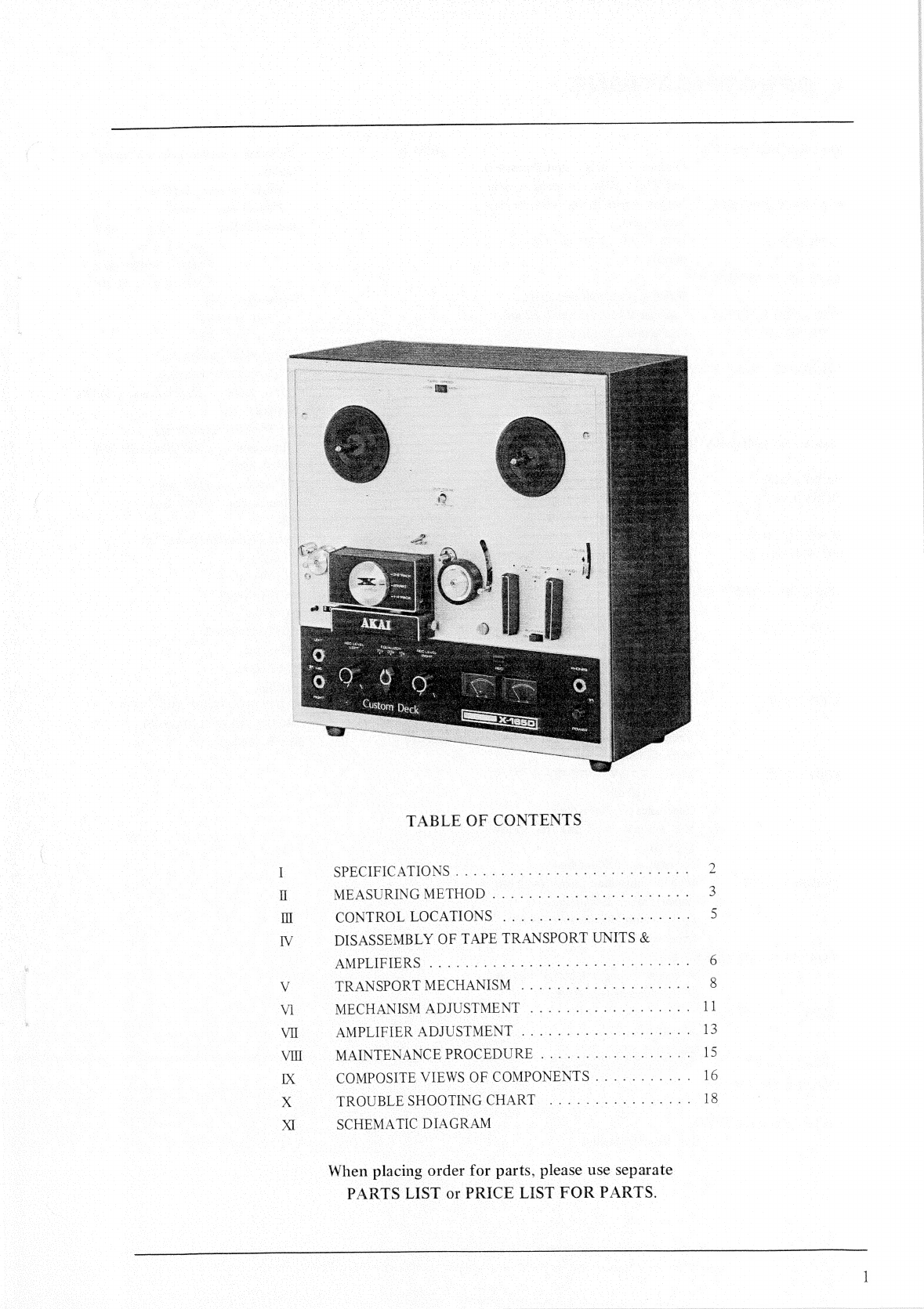
Akai X-165D User manual


ae
ee
xx
RS
SS
<
TABLE
OF
CONTENTS
SPECIPICALIONS
oe
a
es
MEASURING
METHOD
3.0650
00a
Sete
a
CONTROL:
LOCATIONS
©
eee
eee
a
ale
eer
a
eae
DISASSEMBLY
OF
TAPE
TRANSPORT
UNITS
&
AMPUIPIPRS
3.
Sito
3
tie
eee
Se
ee
yee
ae
es
TRANSPORT
MECHANISM
.
MECHANISM
ADJUSTMENT
AMPLIFIER
ADJUSTMENT
.
MAIN
FENANCE
PROCEDURE:
oc
iu5.
Viena
eae
COMPOSITE
VIEWS
OF
COMPONENTS
TROUBLE
SHOOTING
CHART
ea
oe
a
an
SCHEMATIC
DIAGRAM
* *
«
.
.
«
. *
*
.
« *
a
.
*
*
.
e
*
* .
*
*
*
«
*
« *
«
ry
° * .
. . *
.
* *
*
*
*
«
*
* . * .
*
* * *
*
*
.
° « . .
. .
*
*
a
.
When
placing
order
for
parts,
please
use
separate
PARTS
LIST
or
PRICE
LIST
FOR
PARTS.
mn
WD
bY
LI
13
ie
16
18

l.
SPECIFICATIONS
RECORDIING
SYSTEM
Cross-Field
Head
recording
system.
PLAYBACK
SYSTEM
:
In-Line
4
track
stereo/monaural
play-
back
system.
TAPE
SPEED
1-7/8,
3-3/4,
7-1/2
ips
(15
ips
op-
tional)
TAPE
SPEED
DEVIATION
Within
+
1.5%
at
all
tape
speeds.
WOW
AND
FLUTTER
:
Less
than
0.15%
r.m.s
at
7-1/2
ips.
(Playback
only)
Less
than
0.20%
r.m.s
at
3-3/4
ips.
Less
than
0.30%
r.m.s
at
1-7/8
ips.
FREQUENCY
RESPONSE
30
to
22,000
Hz
at
7-1/2
ips.
(+3
dB)
30
to
18,000
Hz
at
3-3/4
ips.
30
to
9,000
Hz
at
1-7/8
ips.
SIGNAL
TO
NOISE
RATIO
:
Better
than
46
dB
DISTORTION
With
in
3%
at
1,000
Hz
OVU
recording.
CROSS
TALK
Less
than
—65dB
(Monaural)
Less
than
—43
dB
(Stereo)
ERASE
RATIO
Less
than
—70
dB
for
all
tracks
EQUALIZATION
Correct
equalization
for
playback
of
tapes
recorded
to
the
NAB
curve.
RECORDING
BIAS
FREQUENCY
:
60kHz
+5
kHz
1.228
V
(+4dB)
at
using
250
Hz
OVU
recorded
tape.
Required
Load
Impedance...
More
than
25
k-Ohms
OUTPUT
(LINE)
DIN
OUTPUT
0.4
V
(—6
dB)
using
a
250
Hz
OVU
recorded
tape.
Impedance
10
k-Ohms.
Required
Load
Impedance...
More
than
50
k-Ohms
INPUT
LEVEL
Line...20mV
(—32dB)
to
2.5
V
(10
dB)
Impedance
..
.
390
k-Ohms
Mic
0.5mV
(—64dB)
to
50mV
(—25
dB)
Impedance...
50
k-Ohms
High
...more
than
20
mV
(—32
dB)
Impedance
..
.
390
k-Ohms
Low
...more
than
5
mV
(—44
dB)
|
Impedance
..
.
68
k-Ohms
F.FORWARD
AND
REWIND
TIME
90
seconds
using
a
1,200
ft.
tape
at
50
Hz,
75
seconds
at
60
Hz
HEAD
PHONE
OUTPUT
30
~40
mV
Impedance
8
Q
100
to
240
V
AC,
50/60
Hz
DIN
INPUT
LEVEL
POWER
SUPPLY
POWER
CONSUMPTION
S55
VA
INSULATION
RESISTANCE
More
than
50
M-Ohms
In-Line
4
track
stereo/manaural
MOTOR
Hysteresis
synchronous
2
speed
motor.
Horse
Power...
1/100
HP
Power
Ratio...
85%
Revolution
...
3,000
and
1,500
r.p.m.
at
50Hz.
3,600
and
1,800
r.p.m.
at
60
Hz
Condenser
capacity
...
2.8
uF
at
50
Hz
2.0
uF
at
60
Hz
HEADS
Recording/playback
head
4
Track
Gap
2
microns
Impedance
...
1.2
k-Ohms
at
1,000
Hz
Bias
head
4
Track
...
Gap
0.2
mm
Impedance
...
500
Ohms
at
60
kHz
ERASE
head
4
Track
...
Gap
0.2
mm
Impedance
...
500
Ohms
RECORD
LEVEL
INDICATOR
:
Vertical
indication
Model
‘‘A”’
VU
meter
x
2
TRANSISTORS
USED
:
2SC650
(A)
x
4
2SC281
(B)
x
4
2SC458
(B)
x
2
28C971
(2)(3)
x
2
DIODES
USED
IN34A
x
2
SW-05-02
x
2
STYLE
Portable
DIMENSIONS
13-1/2"
(H)
x
13-1/2”
(W)
x
9"
(D)
(340
H
x
340
W
x
230
D
mm)
WEIGHT
30.8
lbs
(14
kg)

Wl.
MEASURING
METHOD
TAPE
SPEED
DEVIATION
1.
Method
involving
use
of
pre-recorded
tape.
For
measuring
the
tape
speed
deviation,
play
back
a
pre-recorded
tape
at
1,000Hz
+
0.1%.
Connect
the
appropriate
output
to
a
frequency
counter
meter
in
order
to
measure
the
tape
speed
deviation
from
the
pre-recorded
tape.
2.
Method
involving
use
of
timing
tape.
(designed
for
tape
speed
measurement)
This
method
utilizes
a
timing
tape
marked
at
intervals
of
7-1/2”.
The
running
time
of
over
60
marked
sections
of
tape
is
measured
in
order
to
calculate
the
deviation
of
the
tape
speed.
In
applying
this
method,
however,
it
should
be
kept
in
mind
that
timing
tape
stretch
or
contract
measurement
error
is
inevitable,
so
that
it
is
necessary
to
measure
the
total
length
of
the
tape
in
advance.
WOW
AND
FLUTTER
Playback
a
3,000
Hz
pre-recorded
tape
of
which
the
wow
and
flutter
level
is
guaranteed
to
be
smaller
than
0.07%
for
measurement
by
means
of
a
wow
meter.
It
is
also
possible
for
a
3,000
Hz
sine
wave
to
be
recorded
and
played
for
measurement
by
means
of
the
wow
meter.
In
this
case,
however,
the
wow
meter
indicates
a
value
as
much
as
twice
the
value
given
in
the
specifi-
cations.
SIGNAL
TO
NOISE
RATIO
X-165D
_
Set
the
Equalizer
Switch
to
“7-1/2”
ips
position
and
playback
a
tape
containing
a
250
Hz
sine
wave
recorded
at
“0”
VU
level
on
a
standard
recorder.
Connect
a
V.T.V.M.
to
the
line
output
jack
of
th
recorder
and
measure
its
output.
|
Then
remove
the
tape
and
measure
the
noise
level
under
the
same
condition.
Convert
each
of
the
measured
values
into
decibels.
TOTAL
HARMONIC
DISTORTION
FACTOR
1
kHz
Audio
Distortion
Oscillator
Meter
Connect
the
measuring
instrument
as
shown
above,
and
record
a
1,000
Hz
sine
wave
at
“OQ”
VU.
Playback
the
resultant
signal
and
measure
the
overall
distortion
factor.
Measure
the
noise
level
of
the
tape
recorder
with
the
tape
removed
;
connect
the
audio
oscillator
directly
to
the
distortion
meter
for
measurement
of
the
distortion
factor
of
the
oscillator.
The
required
distortion
factor
can
be
obtained
from
the
results
of
the
above
measurement
by
the
following
formula.
do
=
d—d,
—d,
where,
do
=
Required
d
=
Overall
distortion
factor
d,
=
Noise
level
d,
=
Distortion
factor
of
the
oscillator
(Note
:
New
tape
of
particularly
good
quality
should
be
used
for
measurement
of
the
distortion
factor.)
POWER
OUTPUT
Playback
a
tape
containing
a
250
Hz
sine
wave
recorded
at
O
VU
on
a
standard
recorder.
Connect
a
V.T.V.M.
to
the
line
output
jack
of
the
recorder
and
measure
the
voltage
at
the
output
of
the
recorder
to
be
tested.
ae
a
ee
ee
eee
ae
ey
ry

CROSSTALK
(Crosstalk
between
the
tracks)
(TAPE)
@
2
}
|
BRA
AICS
Tl
Tape
direction
@—-+(WW
wut
Roe
-
Tape
direction
As
shown
in
the
figure,
first
record
a
1,000
Hz
sine
wave
on
track
No.3
at
+3
VU
level.
Next,
remove
the
1,000
Hz
input
signal
and
record
under
a
non-input
condition.
Then,
playback
the
tape
on
track
No.3
and
No.
1
(reversed
condition
of
tape)
through
the
1,000
Hz
B.P.F.
(Band
Pass
Filter,
Sensitivity
...
1:
1)
and
obtain
a
ratio
between
the
two
from
the
following
formula.
Eo
=
201
C
og
E,_E,
(dB)
C
=Desired
crosstalk
ratio
(dB)
be
=
7
3]
Eo
=
1,000
Hz
signal
output
level
TOTTI
E2
=
1,000
Hz
crosstalk
output
level
reer
E,
=No-input
signal
record
level
FREQUENCY
RESPONSE
Audio
Frequency
F-
Oscillator
Connect
the
measuring
instrument
as
shown
in
the
above
diagram,
and
measure
the
frequency
response
according
to
the
following
sequence
:
RECORD
:
1)
Supply
a
sine
wave
of
1,000
Hz
to
the
Line
Input
of
the
recorder
being
tested,
through
an
attenuator
from
an
audio
frequency
generator.
2)
Set
the
Mode/Selector
Lever
to
“Rec”
position
and
adjust
the
line
input
volume
so
that
the
VU
meter
needle
indicates
“0”
VU.
3)
Under
the
condition
described
in
(2),
lower
the
input
level
16
dB
with
the
attenuator.
4)
Record
the
spot
frequency
from
the
audio
frequen-
cy
generator
in
the
range
of
30
Hz
to
25,000
Hz.
PLAYBACK
:
5)
Set
the
Equalizer
Switch
to
7-1/2”
or
3-3/4”.
6)
Connect
a
V.T.V.M.
to
the
Line
output.
7)
Playback
the
previously
recorded
tape.
8)
Adjust
the
output
level
to
“O”
dBm
at
1,000
Hz
(indicated
on
the
V.T.V.M.
Range
selector)
9)
Playback
the
recorded
spot
frequencies
under
the
conditions
in
(8),
make
a
memo
of
Output
Level,
and
plot
the
value
on
a
graph.

Ree}
Retainer
(Left)
Speed
Change
Switch
Supply
Reel
Shaft
Take-Up
Reel
Shaft
Cycle
Conversion
Switch.
‘A)
Reel
Retainer
(Right)
Capstan
Storage
Post-
tation.
WCU
Ee
j
=
Vapstan
Shaft
Track.
Selector
Knob
=
i
Capstan
Head
Cover.
(A)
Pinch
Wheel
Tape
Guide
Automatic
Shut-
Off
Lever
Tape
Cleaner
Record/Playback
Knob
Tape
Cleaner
Release
Button
Pause
Lever
Index
Counter
Reset
Button
Fast-Forward/Rewind
Knob
;
Head
Cover
(B
Recording
Level
Control
Knob
(Right
/-
—Recording
Safety
Buttc
S
ron
Automatic
Shut-Off
Switch
Equalizer
Switch
Recording
Lamp
Microphone
Jack
‘Left)
Stereo
Headphone
Jack
Microphone
Jack.
(Right)
Recording
Level
Control
Knob
(Left)
VU
Meter.
(Right)
Power
Switch
“VU
Meter
CUE
RLS:
—Fuse
Post
Voltage
Selector
Cycle
Conversion
Switch
(B)
AC
Cord
DIN
Jack
and
High/Low
Input
Selector
Switch
Line
Input
Jack
(Left)
Line
Output
Jack
(Left)
Line
Output
Jack
(Right)
f
Line
Input
Jack
(Right)

In
case
of
trouble,
etc.
necessitating
disassembly,
please
disassemble
in
the
order
shown
in
photographs.
Reas-
semble
in
reverse
order.
CAPS
PINCH
WHEEL
PINCH
WHEEL

gMECH.
PANEL
ee
psp
“AMP
BLOCK
~]

1.
CAPSTAN
DRIVE
Figure
1.
(A)
Motor
(B)
Drive
Belt
(flat
belt)
(C)
Capstan
(D)
Flywheel
High-speed
rotation
of
Motor
(A)
is
transmitted
by
Drive
Belt
(B)
to
Capstan
(C),
which
is
connected
to
a
flywheel
that
provides
necessary
inertia.
This
flywheel
maintains
the
rated
rotation
and
absorbs
minor
rotation
variations
of
the
motor.
Capstan
Rotation
:
606
R.P.M.
at
7-1/2”
(19
cm)
per
sec.
303
R.P.M.
at
3-3/4”
(9,5
cm)
per
sec.
151.5
R.P.M.
at
1-7/8”
(4.74
cm)
per
sec.
Motor
Rotation
:
3,000
to
1,500
R.P.M.
at
50
Hz
3,600
to
1,800
R.P.M.
at
60
kHz
2.
PINCH
WHEEL
DRIVE
Place
tape
between
the
rotating
capstan
and
pinch
wheel
and
push
pinch
wheel
against
capstan
to
transport
the
tape
at
rated
speed.
The
proper
pinch
wheel
pressure
is
between
1,000
to
1,150
grams
at
the
tape
speed
of
7-1/2”
(19
cm)
per
second.
3.
RECORD
AND
PLAYBACK
MECHANISM
a
Turning
the
RECORD/PLAYBACK
LEVER
(A)
to
Slipping
Rotation
ER
;
:
Gy
Fa
O
“PLAY”
position
causes
the
pinch
wheel
to
press
against
le
NN
the
capstan
and
move
the
tape
at
the
rated
speed.
At
the
same
time,
Idler
(B)
moves
between
Motor
Bushing
(C)
and
the
Take-Up
Reel
Spindle
(D)
to
transmit
the
motor
|
rotation
to
(D)
so
that
the
tape
is
moved
and
wound
on
)
the
take-up
reel.
The
Take-up
Reel
Spindle
Base,
composed
of
two
plastic
wheels
(discs)
(1
and
2)
witha
felt
clutch
between,
is
rotated
from
below
by
the
idler.
Tape-winding
friction
is
adjusted
by
the
slipping
of
the
felt
and
maintains
rated
winding
of
the
tape.
The
Supply
Reel
Spindle
(H)
has
a
Brake
Roller
(E)
contacting
plastic
wheel
(disc)
(4)
from
below which
provides
appropriate
back
tension
by
the
slipping
of
the
felt
clutch
to
the
rotation
of
the
Pulley
(3)
above.
To
prevent
accidental
erasure,
the
Record
Interlock
Button
(F)
must
be
depressed
before
the
RECORD/PLAYBACK
LEVER
can
be
moved
to
the
“REC’’
position.
Safety
device
(G)
is
depressed
to
operate
the
recording
mecha-
nism.
2
(See
figure
2)
AWWA

4.
FAST-FORWARD
MECHANISM
Turning
the
FAST
FWD-REWIND
knob
(A)
to
“FAST
FWD”’
position,
causes
the
cam
(B)
under
the
knob
to
push
up
Lever
(C).
Idler
(D)
moves
into
the
space
between
Plastic
Roller
(F)
above
the
Take-Up
Reel
Spindle
and
the
upper
part
of
the
rotating
motor.
drive
|
bushing
to
transmit
the
motor
rotation
to
the
take-up
|
reel
spindle.
At
the
same
time,
Brake
Rollers
(H)
and
(1)
comes
off
the
reel
spindle
to
free
the
Supply
Reel
Spindle
(G),
thereby
allowing
fast
winding
of
the
tape
onto
the
take-up
reel.
(See
figure
3)
Free
Rota
5.
REWIND
MECHANISM
Turning
the
FAST
FWD-REWIND
knob
(A)
to
“RE-
WIND”
position,
causes
the
cam
(B)
under
the
knob
to
push
Lever
(C)
up.
Idler
(D)
moves
into
the
space
between
the
upper
part
of
the
rotating
Motor
drive
bushing
(E)
and
the
Intermediate
Pulley
(F)
to
/
transmit
the
high-speed
rotation
of
the
motor
through
:
:
ODF
NS
aa
{
—
the
intermediate
pulley
to
the
Supply
Reel
Spindle
(G).
eee
2
os
ee
i
the
same
time,
Brake
Rollers
(H)
and
(1)
come
off the
ee
:
~
©
reel
spindle
to
free
the
take-up
reel
spindle
(J),
thereby
rewinding
the
tape
onto
the
supply
reel
at
a
fast
speed.
|
(See
figure
4)
Free
Rotation
ae
if
Or
thee
deo
i
i
ie
RAL
ee
pte
Fig.
4
serena
oo)
6.
STOP.
CONTROL
gee
ree
newine
ee
|
Turning
the
stop
lever
to
the
“STOP”
position,
causes
/
foo
=
lerwheel
fe
\
a
\
|
|
|
Brake
Rollers
(A)
and
(B)
to
depress
the
reel
spindles
and
stop
rotation.
\
As
the
brake
rubbers
depress
the
plastic
rollers
below
the
Se
'
reel
spindles,
no
friction
is
applied
to
the
tape.
(A)
\
oe
“(See
figure
5
,
side
Brake:
ace
=
|Idlerwheel
;
a
eh
.
2
eg
‘C
LT
A
=
><
ea
cd
|
Ne
oe
ae
el
See
ee
eas
x
EN
po
-Capstany
iN
O
i
|
Head
o
ae
Li
fER
Ss
Saee
=
Block
|
|
Pinch
|
(CaM)
Guide--Roller:
Genes
DU
Wai
eee
wee)
ies
ete
Pinch
Take-up
|
Rewind
|
Take-up
|
Supply
a
Modes
of
Operation
Wheel
Idler
Idler
side
side
Wheel
Wheel
|
Brake
Brake
L
(a)
STOP
x
x
x
0
.
(b)
FAST-FORWARD
x
O
x
x
x
(c)
REWIND
x
x
O
x
x
RECORDING
5
;
;
(2)
PLAYBACK
:
ss
x
x
°
NOTES
:
X-Marks
indicate
“open”
and
o-marks
“engaged”

TRESS
RECORD/PLAY
BACK
CHANGING
MECHANISM
Turning
the
RECORD/PLAYBACK
LEVER
(N)
to
recording
position
causes
LEVER
(a)
to
push
RECORD-
ING
LEVERS
(b)
and
(c)
as
illustrated
by
the
dotted
lines.
The
RECORD/PLAYBACK
CHANGING
SWITCH
(SWI)
then
turns
to
recording
position.
If
LEVER
(b)
does
not
push
LEVER
(c)
properly,
abnormal
oscillation
may
occur
and
also
the
inability
to
record.
Should
this
be
the
case,
adjust
LEVER
(b)
by
loosening
SCREW
(d).
10
SSSA
GEIS
ENS
NOTES
SW...
STOP
51
ay
®
we
ON
Te
we
EUR
ES
a8
SE
a
ee
PS
te
Ney
SE
SSE
SASS
RAKE
<
2S
SENN
ee
Pay
i
PF,
POD
Fig.
6

reel
table
base
plate
VI.
MECHANISM
ADJUSTMENT
ST
TTTTET
TEESE
TIC
nnn
TOT
nnn
aad
adtttsttEEtEEEESaan
ae
1.
PINCH
WHEEL
ADJUSTMENT
It
is
important
that
the
pinch
wheel
shaft
be
kept
in
perfect
alignment
with
the
capstan
shaft.
Proper
pinch
wheel
pressure
is
between
1,000
and
1,150
grams
when
the
unit
is
operated
at
the
tape
speed
of
7-1/2
ips.
Any
deviation
from
this
specification
will
result
in
wow
and
flutter.
Check
pinch
wheel
pressure
with
a
spring
scale,
and
if
necessary,
adjust
the
pinch
wheel
load
spring.
2.
TAKE-UP
IDLER
WHEEL
ADJUSTMENT
The
take-up
idler
wheel
must
be
kept
in
perfect
alignment
with
the
take-up
reel
shaft.
In
fast
forward
operation,
the
idler
wheel
contacts
the
upper
knurled
wheel
of
the
take-up
reel
shaft
assembly,
and
conversely
contacts
the
lower
knurled
wheel
during
record
or
play
operation.
Adjust
idler
wheel
load
spring
so
that
the
idler
wheel
pressure
is
kept
between
50
and
80
grams.
The
idler
wheel
wears
rapidly
if
the
pressure
is
excessive.
Slippage
occurs
if
the
pressure
is
less
than
specified.
(a)
Rewind
reel
shaft
assy.
(b)
Take-up
ree!
shaft
assy.
reel
shaft
__
ba
reel
table
__
reel
stcpper
felt
Alutch
|
drive
shaft
rewind
rubber
ABE
ring
rewind
pulley
===
conical
spring
=
netal
washer
felt
clutch
a
retainer
HN
take-up
washer
drive
wheel
ay
.
Le
eed
ain
Star-shaped
spring
Laiibaass
washer
—-+===">>
metal
washer
=
retainer
—~—“s=——nylon
washer
|
i
plate
oil
ee
oilite
metal
mtg.
plate
TF
oilite
metal
Hf
star-shaped
—pom
:
oe
spring
for
brake
|
==-—Paper
washer
3
coil
spring
ate
+
-
1
ia
retainer
__wasner
|
pulley
B
=———retainer
x:
nylon
——
washer
57
set
sleeve
Fig.
|
3.
REWIND
IDLER
WHEEL
ADJUSTMENT
The
rewind
idler
wheel
must
be
kept
in
perfect
alignment
with
the
rewind
reel
shaft.
The
amount
of
pressure
on
the
knurled
motor
bushing
should
be
about
50
grams
during
rewind
operation.
Adjust
both
the
idler
load
spring
and
rewind
roller.
4.
INTERMEDIATE
WHEEL
ADJUSTMENT
The
intermediate
wheel
is
located
between
the
rewind
idler
wheel
and
the
rubber
ring
which
is
used
on
the
upper
part
of
the
supply
reel
shaft
assembly.
In
rewind
condition,
it
contacts
these
parts
while
simultaneously
transmitting
motor
torque.
An
adequate
pressure
is
50
grams.
Adjust
the
load
spring
of
the
intermediate
wheel
if
the
pressure
is
not
sufficient.
5.
TAKE-UP
REEL
SHAFT
ASSEMBLY
ADJUSTMENT
Felt
clutch
material
is
attached
to
the
bottom
side
of
the
reel
table
base
plate
so
that
recording
tape
will
not
stretch
during
fast
forward
operation
due
to
excessive
tension.
To
check
the
amount
of
friction
of
this
part,
install
a
5-inch
reel
with
a
60
m/m
diameter
tape,
and
gently
pull
the
end
of
tape
upward
with
a
spring
scale.
Adjust
the
conical
spring
so
that
the
amount
of
tension
at
this
part
is
kept
between
400
and
500
grams.
Other
felt
clutch
material
is
attached
to
the
take-up
drive
wheel.
This
is
to
provide
proper
slippage
during
record
or
play
operation.
The
procedure
for
checking
friction
of
this
part
is
the
same
as
the
foregoing,
and
between
150
and
200
grams
of
friction
provides
the
best
results.
Adjust
the
star-shaped
spring
just
under
the
take-up
drive
wheel.
When
the
unit
is
set
to
rewind
operation,
the
amount
of
friction
of
this
part
will
decrease
to
from
15
to
20
grams.
Check
to
see
whether
this
is
satisfactory.
If
not,
readjust
the
star-shaped
brake
spring
and
the
pressure
of
the
spring
retainer
washer
accordingly.
(See
figure
1
(b)
at
right)
6.
SUPPLY
REEL
SHAFT
ASSEMBLY
ADJUSTMENT
Felt
clutch
material
is
used
between
the
lower
side
of
the
reel
table
base
plate
and
the
rewind
rubber
ring
to
protect
recording
tape
from
excessive
tension
during
rewind
operation.
To
check
the
amount
of
friction
of
this
part,
place
onto
the
supply
reel
table
a
5-inch
reel
with
a
60
m/m
diameter
tape,
and
gently
pull
the
end
of
tape
upward
with
spring
scale.
Adjust
the
conical
spring
so
that
the
tension
is
between
400
and
500
grams.
Other
felt
clutch
material
is
attached
to
the
rewind
drive
wheel
to
provide
proper
slippage
during
record
or
play
ope-
ration.
The
procedure
for
checking
friction
of
this
part
is
the
same
as
the
foregoing,
and
between
100
and
120
grams
of
friction
gives
best
results.
When
the
unit
is
set
to
fast
forward
operation,
the
amount
of
friction
will
decrease
to
from
15
to
20
grams.
Check
to
see
whether
this
is
correct.
If
not,
readjust
coil
spring
and
spring
retainer
washer.
(See
figure
1
(a)
at
left)
1]
SAM
Sd
ante
INR
Oden
EN
A
i
a
ome
aN
AD
ZS

Fig.
2
Fig.
3
f=g=0.2mm~0.3mm
Fig.
4
Fig.
5
a)
b)
Cc)
d)
.
HEAD
ADJUSTMENT
Position
the
Erase
Head
about
0.125
mm
above
the
upper
edge
of
the
tape
by
adjusting
the
height
cam
provided
in
the
lower
part
of
the
head
assembly.
Adjust
the
height
of
the
Recording/Playback
Head
to
0.025
mm
above
the
upper
edge
of
the
tape
by
adjusting
the
control
nut
at
the
lower
part
of
the
head
assembly.
Adjustment
of
Playback
Head
Alignment
Playback
an
Ampex
Alignment
tape
(8,000
Hz)
at
7-1/2
ips
tape
speed
and
turn
alignment
screw
(A)
until
the
output
level
of
both
channels
reaches
maximum.
Clearance
of
the
Bias
Head
(See
Fig.
4,
5)
Loosen
the
two
Bias
Head
Screws
and
move
the
Bias
Head
by
hand
until
the
clearance
(f)
and
(g)
is
0.2
to
0.3
mm.
Then
tighten
screws.
Note
:
If
the
clearance
(f)
and
(g)
becomes
less
than
0.2
to
0.3
mm,
the
frequency
characteristic
will
be
too
low,
but
distortion
will
decrease.
If
the
clearance
(f)
and
(g)
becomes
more
than
0.2
to
0.3
mm,
the
frequency
charasteristic
will
be
too
high,
and
distortion
will
increase.
12

Vil.
AMPLIFIER
ADJUSTMENT
a)
b)
Cc)
d)
Bias
Head
102
~50
0
.
RECORDING
BIAS
FREQUENCY
ADJUSTMENT
Put
a
resistor
(10
Q
or
50
2)
in
series
with
the
bias
head,
and
connect
the
signal
from
the
resistor
to
the
vertical
input
of
the
oscilloscope.
Feed
a
sine
wave
signal
from
an
Audio
Frequency
Oscillator
to
the
Horizontal
Input
of
the
Oscil-
loscope
and
tune
the
dial
of
the
Audio
Oscillator
until
the
Oscilloscope
displays
a
circular
or
linear
pattern.
|
A
reading
of
60
kHz
+
5
kHz
indicates
that
the
Recording
Bias
Frequency
is
correct.
If
incorrect,
it
can
be
adjusted
by
adjusting
the
value
of
condenser
C-402
(3000
pF).
OSCILLOSCOPE
Ze:
a)
Oscillator
Circuit
AUDIO
FREQUENCY
OSCILLATOR
Fig.
|
¢
x
RECORDING
BIAS
VOLTAGE
ADJUSTMENT
Connect
a
V.T.V.M.
to
the
bias
head
and
fix
the
recording
bias
voltage
by
adjusting
the
V.A.C
in
the
bias
oscillator
circuit
(located
near
the
head
as-
sembly)
until
its
reading
becomes
equal
to
the
bias
voltage
stamped
on
the
back
of
the
head
assembly.
Normal
bias
voltage
is
between
60
V
and
70
V,
while
acceptable
terminal
voltage
of
the
erase
head
is
between
12
V
and
18
V.
13
GA
A
tpl
Me
SAE
pln
ah
CE
Aa
ID

a)
b)
Cc)
a)
b)
c)
d)
14
_
LINE
OUTPUT
LEVEL
ADJUSTMENT
Connect
a
high
sensitivity
V.T.V.M.
to
the
Line
Output
Jack.
Playback
a
250Hz
pre-recorded
test
tape
at
7-
1/2
ips.
Adjust
VR-201
(LEFT
and
RIGHT
CH.
semi-fixed
resistor
20
KQQB)
of
the
pre-amplifier
(CD-513)
so
that
the
Line
Output
Voltage
is
1.228
V
(+4
dBm).
RECORDING
LEVEL
ADJUSTMENT
Recording
level
adjustment
should
be
made
only
after
“Head
Adjustment”
and
“Line
Output
Level
Adjustment”
has
been
made.
As
shown
in
Fig.3,
connect
an
Audio
Signal
Generator
and
Attenuator
to
the
Line
Input.
Con-
nect
a
high
sensitivity
V.T.V.M.
to
the
Line
Output.
Line
Line
Input
Output
|
Fig.
3
Set
Equalizer
Switch
and
Tape
Speed
Selector
to
7-1/2
ips.
Load
a
blank
test
tape
(Fuji
FYS-100
or
Scotch
No.
150).
Supply
a
1,000
Hz
signal
from
the
audio
signal
generator
to
the
Line
Input,
and
adjust
each
of
the
Volume
Controls
so
that
each
of
the
Line
Output
voltages
is
1.228
V
(+4
dBm).
Record
the
signal
on
the
tape
and
check
playback
to
see
whether
Line
Output
Voltage
is
1.228
V
(+4
dBm).
If
Line
Output
Voltage
fails
to
register
1.228
V
(+4
dBm),
while
repeating
recording
and
playback,
adjust
semi-fixed
resistors
VR-101
(LEFT
and
RIGHT
CH,
2
KQ-B)
until
1.228
V
(+4
dBm)
is
obtained
both
on
recording
and
playback.

FEYWHEEL
@
|
drop
MOTOR
1.
LUBRICATION
INSTRUCTIONS
2.
CLEANING
TAPE
HEADS
AND
OTHER
For
maximum
service
life
and
optimum
performance,
PARTS
lubricate
the
following
parts
after
each
500
hours
of
Wipe
surface
of
tape
heads,
guide
roller
bearing,
capstan
operation.
Use
only
light
machine
oil
of
good
quality.
bushing
and
pinch
wheel
periodically
with
a
soft
cloth
Motor
soaked
in
alcohol.
Flywheel
Assembly
Rewind
Idler
Wheel
and
Wind
Take-Up
Idler
1
drop
Intermediate
Idler
1
drop
Pinch
Wheel
1
drop
Also
apply
a
liberal
film
of
light
machine
grease
to
each
roller
surface
of
all
levers
and
cams.
CAUTION
:
DO
NOT
OVER-LUBRICATE,
AND
WIPE
OFF
EXCESS
OIL
WITH
A
COTTON
SWAB
SOAKED
IN
ALCOHOL.
OTHERWISE,
EXCESS
LUBRICANT
MAY
BE
SCATTERED
DURING
OPERATION
AND
THE
RUBBER
COMPONENT
PARTS
WILL
DETERIORATE.
iB)

16
TR204,203,
25C281(B)
|
eeneerccior
eee
rent
|
120K)
F -
-A
R209
to
ee
a
|
eaters
rea
erator
ries
|
—4
R204
3:3k
i
cr
Id
jl
|
|
pd
|
bl
1
4
|
L
cecateneernes
meee
ee.
©
—
R208
100k
ke
é
HAR2O03)
150K
ie
TR201,202,
2SC650(A)(B)

3.
OSC.
P.C.
BOARD
(MR-505)
i

X.
TROUBLE
SHOOTING
CHART
SECTION
‘‘A’’
TROUBLE
WITH
AMPLIFIER
1.
Playback
problems.
(Unit
set
to
play
position.)
Silicon
diode
(SW05-02)
No
sound
from
Line-out
jack
or
R4-1KQ
(2W)
defective
No
B
(+),
voltage
supply
Playback
amp.
card
and
+
l
ete
B
(+),
voltage
supply
socket
loose
connection
P-10,
J-10
loose
connection
Check
transistors
(TR-201,
202,
203
and
TR-204)
Playback
head
coil
open
or
lead
wire
loose
Silicon
diode
(SW05-02),
.
‘os
a
Sound,
but
volume
insufficient
T.
(+),
voltage
low
R4
(1KQ)
Cl
(470uF),
C2
(1000uF)
B
(+),
voltage
normal
Dust
adhering
to
head
———————
-~
transistors
(TR-201,
202,
203
and
TR-204)
Hum
is
decreased
if
playback
head
is
grounded
Hum
bucking
coil
out
Loud
hum
insulation
defective
No
change
even
when
playback
head
is
grounded
Ground
wire
loose
of
adjustment
Playback
head
shield
or
Cl
(470uF),
C2
(1000uF)
defective
Inductive
pick
ae
ieccin
the
recorder
Change
the
set
position
of
the
recorder
Irregular
scratching
or
Playback
card
and
socket
crackling
noise
loose
connection
Transistor
(TR-201,
202)
defective
Squeaking
noise
Tape
itself
defective
ee
is
magnetized
Tape
itself
noisy
Noise
present
Hissing
noise
Le
playing
tape
Not
caused
by
tape—————"_
—_
———
Transistors
(TR-201,
202)
defective
|.
adhering
to
head
surface
Back
tension
weak
Poor
contact
between
head
and
tape
Lack
of
treble
Head
angle
incorrect
Re-adjust
head
angle
Head
worn
out
Replace
Tape
itself
defective
Sound
distorted
Dust
adhering
to
head
surface——————
oss
transistors
———__———-
Replace
Head
worn
out
Replace
Clean
the
head
Replace
mas
(itis
adhering
to
head
surface
Replace
Adjust
Adjust
—-~—
Replace
Clean
ee
Readjust
Replace
Adjust
———
Replace
Adjust
Replace
Clean
Replace
Demagnetize
head
Replace
———-Replace
Clean
Adjust
tension
of
supply
spindle
18

2.
Recording
problems.
(Unit
plays
back
pre-recorded
tapes
satisfactorily,
but
recording
unsatisfactory.)
VU
meter
itself
defective
or
Does
not
record
No
VU
meter
indication
lesd
Wire
détechive
——
Replace
Defective
Input
jack
———~---——
Replace
REC/PLAY
slide
switch
does
Check
record
lever
which
not
function
properly
actuates
slide
switch
VU
meter
indication
normal
Transistor
(TR-101)
defective
Replace
_
Bias
head
does
not
move
———+—~
Adjust
Loose
connection
of
P8
and
J8
——-
Adjust
ao
Components
of
oscillator
circuit
or
oscillator
coil
defective
VU-meter
functions
normally
;
Sound
distorted
recording
monitor
through
headphones
also
normal
P .
ree
Check
recording
bias
voltage
and
Faulty
recording
bias
circuit
7
Sea
ce
components
of
oscillator
circuit
Faulty
recording
Check
transistor
(TR-101)
equalization
circuit
and
L-102
(peaking
coil)
_
Dust
adhering
to
head
surface
Clean
VU-meter
functions
normally
but
recording
monitor
Over
recording
input
level————-
Turn
the
volume
down
a
little
through
headphones
abnormal
VU-meter
lost
sensitivity
-——————
Replace
ae
Defective
input
equipment
(microphone,
etc.)
Faulty
erasing
Does
not
erase
at
all
Erase
head
defective
————+--—-Replace
Disconnected
wire
of
erase
head.
Excessive
amount
of
—
Adjust
dust
adhering
to
surface
of
erase
head
Transistor
(TR-401,
402)
7
Incomplete
erasure
~——---—-
Erasing
bias
voltage
low
aetesiws
Oscillator
coil
defective
Erase
head
coil
defective
Erasing
noise
Defective
recording
tape——~—~~-~--—
Replace
(Popping
noise)
Transistor
(TR-6)
defective
-————
Replace
Head
magnetized
ann
Demagnetize
head
Bias
voltage
out
of
adjustment
Re-adjust
Recording
sensitivity
low
VU
meter
functions
normally
|
Dust
adhering
to
head
surface
Clean
Bias
voitage
out
of
adjustment
Re-adjust
Transistor
(TR-101)
defective
Replace
Tape
itself
defective
—_—————Reep
lace
VU
meter
does
not
Loose
connection
of
Adjust
indicate
properly
the
Input
jack
VU
meter
sensitivity
low
~~"
Replace
REC/PLAY
slide
switch
does
:
——
Adjust
not
function
properly
19
Pare
Peet
yo
Sette
e@sgebiee
tL
Rie
See
re
a,
ate
ae
iy
SE
PO
Oe
eee,
Table of contents
Other Akai Tape Deck manuals