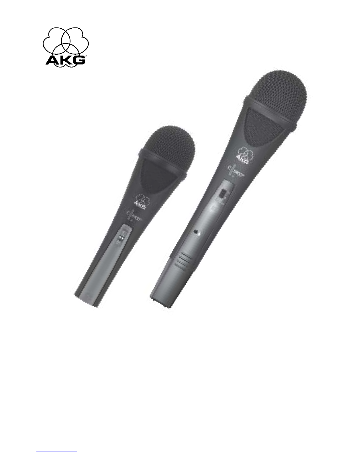
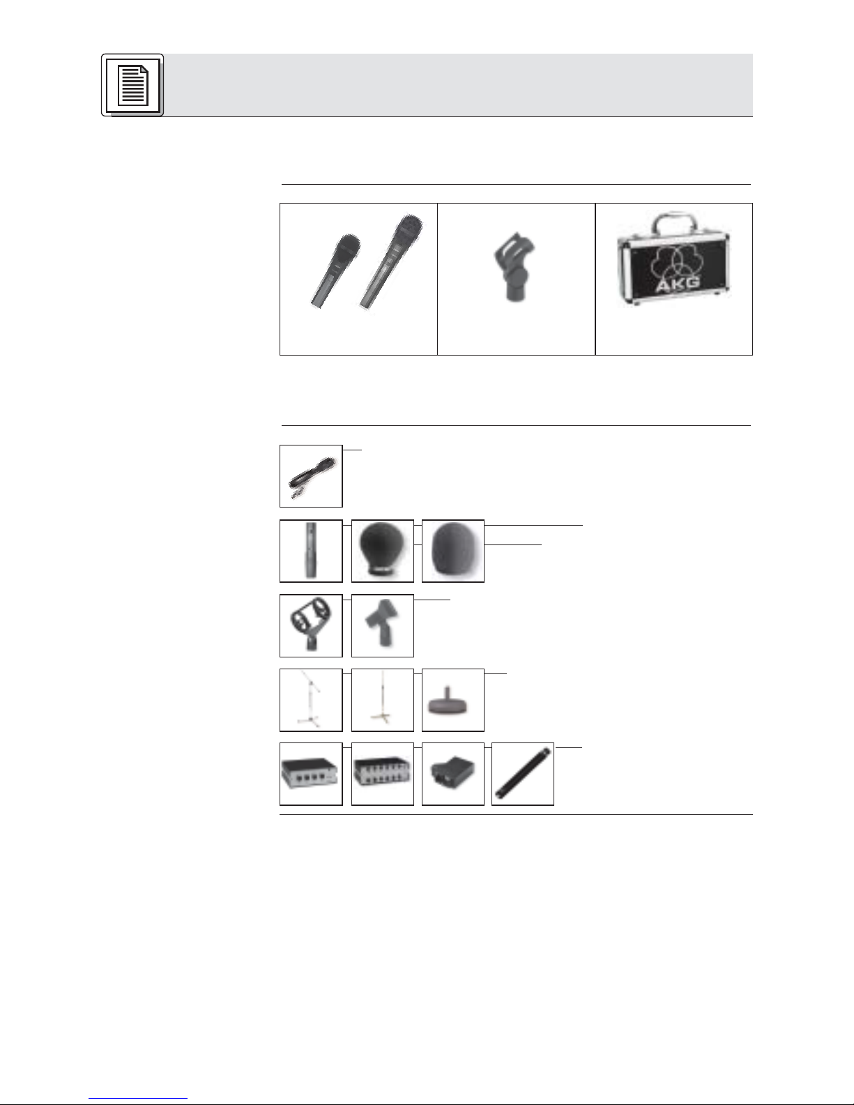
1.5 C 5900M,
C 5900M/TM 40
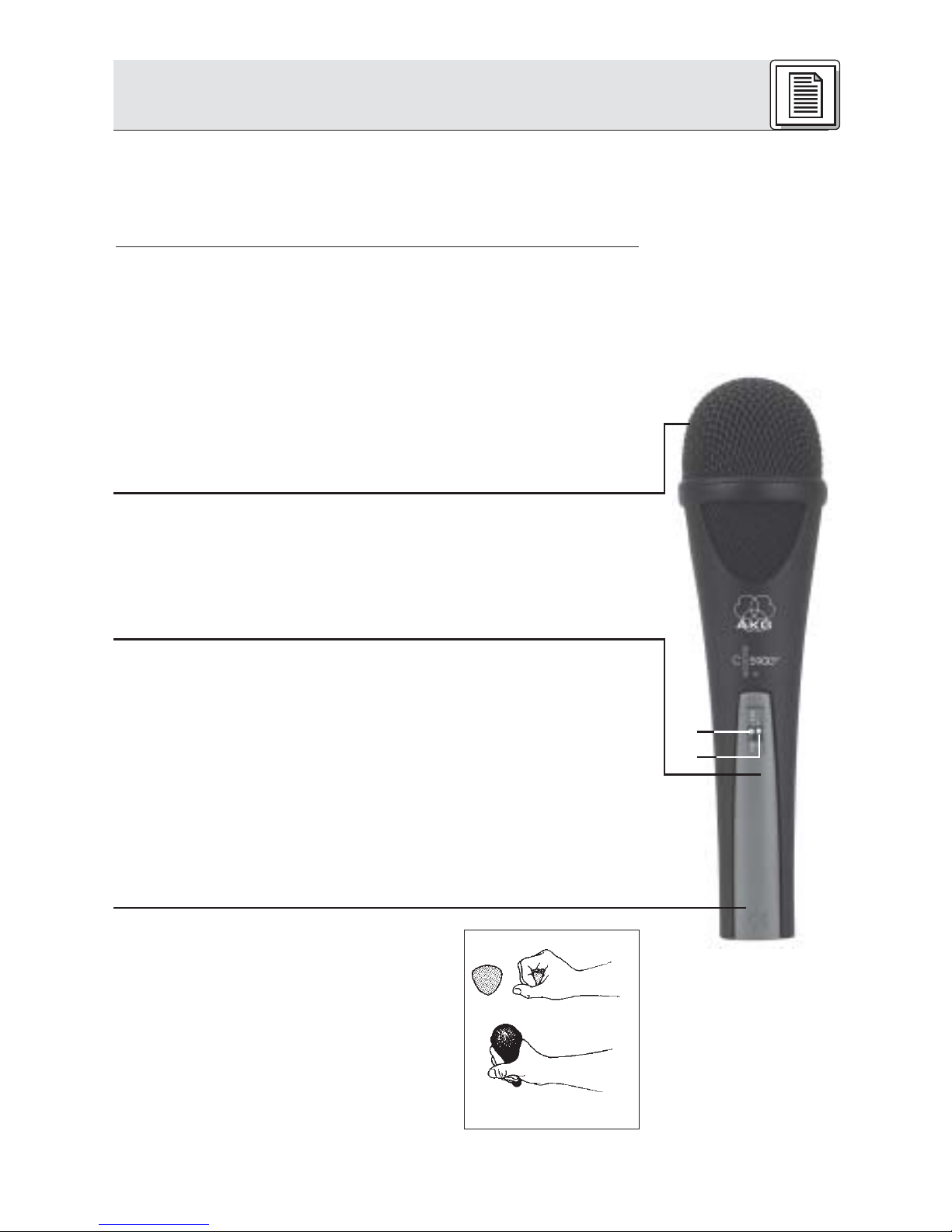
Abb. 1:
Ergonomisch
optimierte
Gehäuseform
•Eingebaute elastische Spinnenlagerung des Wandler-
systems reduziert Griff- und Kabelgeräusche.
•Sicherer Schutz des Mikrofonwandlers durch nahezu unde-
formierbare Gitterkappe aus Federstahl
•Einbauschacht für optionales Sendermodul TM 40
Das C 5900
M
von AKG ist ein Kondensatormikrofon mit super-
nierenförmiger Richtcharakteristik, konzipiert für den
Vokaleinsatz auf der Bühne. Eine leichte Anhebung der
Empfindlichkeit zwischen 3 und 15 kHz verschafft der Stimme
die nötige Durchsetzungskraft auch bei sehr hoher Lautstärke
auf der Bühne und sorgt für gute Textverständlichkeit.
Eine robuste, nahezu unverformbare Gitterkappe aus Feder-
stahl und das stabile Zink-Alu-Druckgussgehäuse schützen
das Mikrofon und die Kapsel wirksam vor Beschädigungen im
harten Alltag "on the road".
Ein Pegelumschalter (1) erlaubt Ihnen, den Ausgangspegel des
Mikrofons zur Anpassung an weniger empfindliche Eingänge
um 6 dB anzuheben.
Ein schaltbares Bass Cut-Filter (2) (-12 dB/Oktave ab 100 Hz)
ermöglicht eine wirksame Ausblendung tieffrequenter Stör-
geräusche.
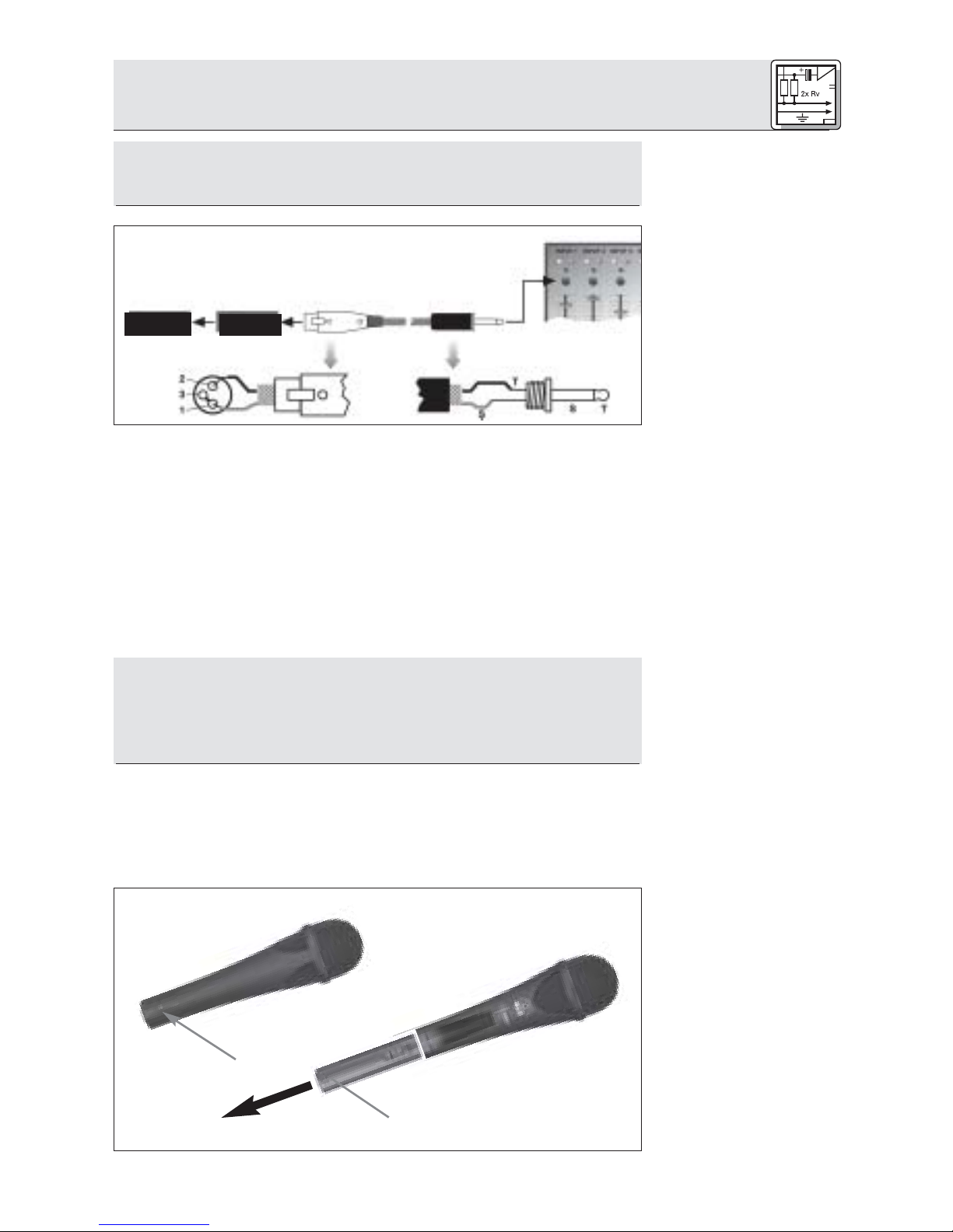
Das Wandlersystem ist nach dem bewährten Backplate-
Kondensatorprinzip aufgebaut. Ein dahinter liegender
Absorptionsring aus Synthetikkautschuk verhindert wie ein
schalltoter Raum das Entstehen von Reflexionen und damit
Veränderungen des Frequenzgangs. Hand- und Kabel-
geräusche werden durch die integrierte Spinnenlagerung des
Wandlers weitgehend unterdrückt. Der Innenwindschutz reduziert
Pop-, Wind- und Atemgeräusche auf ein Minimum.
Das C 5900
M
ist mit einem abnehmbaren Anschlussmodul mit
3-poligem XLR-Stecker ausgestattet. Sie können das C 5900
M
sowohl an symmetrischen als auch asymmetrischen Mischpult-
und Verstärkereingängen betreiben.
Die ergonomisch optimierte Form des
Gehäuses gewährleistet absolute
Funktionalität und exzellente Anwender-
freundlichkeit. Sie haben das Mikrofon
stets voll im Griff, egal, wie Sie es ein-
setzen.
1 Beschreibung
3
1
2