Akw Arka Thermostatic Cool Touch TMV2 User manual

Arka Thermostatic Cool Touch
TMV2 Mixer Shower
INSTALLATION INSTRUCTIONS
Please read all instructions before installation and leave this document
with the end user for future reference as it contains important warranty information
Stock Code
25430

General: 01905 823 298 | www.akw-ltd.co.uk2
2
Components & Dimensions
COMPONENTS & DIMENSIONS
Components
Dimensions
Inlet Cover
Filter
Cold Inlet
Flow Lever
Temperature Lever
3/4” BSP Fitting
Shower Outlet
1/2” BSP Fitting
Hot Inlet
Olive
Wall Plate
Please check that all components are present from the
packaging box prior to installation of this product. If anything
is missing or damaged please contact General Enquiries - see
back page.
25 mm
51
77 mm
48 mm
284 mm
150 mm
152 mm
55 mm
77 mm
60 mm
42 mm
6 mm
G 3/4” - 1/2”
G 1/2”
40 mm
25 mm
51
77 mm
48 mm
284 mm
150 mm
152 mm
55 mm
77 mm
60 mm
42 mm
6 mm
G 3/4” - 1/2”
G 1/2”
40 mm

Technical Support: 01905 560 219 3Order: 01905 823 299 |orders.akw-ltd.co.uk
3
SPECIFICATIONS
Specications
Minimum Dynamic Pressure 0.5 Bar
Maximum Dynamic Pressure 5 Bar
Maximum Static Pressure 10 Bar
Dimensions for Fitting 150 mm
Concealed & Exposed Water Entry Back
Inlet Connectors 3/4” - 1/2” BSP
Valve Type Thermostatic Bar Shower Mixer with
Independent Flow & Temperature Control
Approvals TMV2, WRAS
Maximum Pre-Set Temperature 38 oC
Maximum Pressure Difference
(Between Hot & Cold Water Supply) 1 Bar
Maximum Flow (@ 3 Bar) 19.5 L/Min
Do not choose a position where the shower could become frozen. Do not connect this mixer
shower to any form of tap or fitting not recommended by the manufacturer. Do not allow the
inlet pressure or flow rates to operate outside the guidelines laid out in ‘site requirements’.
This product is precision-engineered and should give continued superior and safe performance,
provided that:
1. It’s installed, commissioned, operated and maintained in accordance with the
recommendations given in this manual and must be conducted by designated, qualied and
competent personnel.
2. Installation must comply with all local/national water supply authority regulations/by-laws
and building and plumbing regulations.
3. Periodic attention is given, as necessary, to maintain the product in good functional order.
This product is designed to deliver water consistently at a safe temperature. In keeping
with every other mechanism, the mixer shower cannot be considered as being functionally
infallible therefore it cannot totally replace the vigilance of nursing/supervisory staff where
that is necessary.
Provided it is installed, commissioned, operated and maintained within these
recommendations, the risk of failure is not eliminated but can be reduced to a minimum.

General: 01905 823 298 | www.akw-ltd.co.uk4
4
INSTALLATION
Installation
Installing the Fast Fit Kit
1. Identify all components are present prior to
starting installation.
2. Mark the position for the pipework and the
xings supplied.
Note: The Pipe centres required for this
thermostatic mixing valve are 150 mm.
Before drilling into walls, check that there are
no hidden electrical wires, cables, or water
supply pipes. This can be done with the aid
of an electronic detector.
3. Drill suitable holes in the wall surface at the
marked positions to accommodate the supply
pipework and xings.
4. Terminate the pipework in the wall, ensuring
that there is at least 30 mm of 15 mm diameter
pipework protruding from the nished wall surface.
Important
Match up the water supply pipes with the
thermostatic mixer valve. The must be with the hot
on the left and the cold on the right when viewed from
the front.
5. Place the inlet cover (1) over the supply pipe.
Use the wall plugs (2) and screws (3) provided
to x the wall plates to the wall.
6. Place the olive (4) onto the protruding
pipework. IMPORTANT: The pipework must not
protrude past the olive (4) by more than 5 mm.
7. Screw 1/2” - 3/4” BSP tting (5) onto the wall
plate (1) using a 24 mm spanner. Repeat this
step on the other side.
8. Screw the covers (6) over the wall plates /
1/2” - 3/4” BSP ttings (5) so that they are ush
against the nished wall surface.
1
2
3
3
5
6
4
5
1
150 mm Centres
30 mm

Technical Support: 01905 560 219 5Order: 01905 823 299 |orders.akw-ltd.co.uk
5
INSTALLATION
Installation
Installing the Arka Care Cool Touch Thermostatic Mixer Valve
1. Place the lters (7) into the 1/2” - 3/4” BSP ttings (5).
2. Position the shower valve threads (8) against the 1/2” - 3/4” BSP ttings (5) and carefully
tighten the shower valve threaded nuts onto them. Do not overtighten.
Note: take care not to damage the nish of the shower valve xing nuts. Protect the chrome
plated surfaces with a cloth.
min
30 mm
5
6
7
7
8
8
Tip: use a spanner around the wall xing
whilst tightening the threaded nut to
securely seal the lter.

General: 01905 823 298 | www.akw-ltd.co.uk6
6
OPERATION
Operation
This product incorporates a cool touch feature. When the shower valve is in use, the body of
the shower will not get hot and will remain cool to touch.
Adjusting the Flow
The ow is controlled by rotating the ow lever on the right side of the mixer. To obtain a
higher ow rate, press the override button on the ow lever and continue to rotate the lever.
Adjusting the Temperature
The temperature is controlled by rotating the temperature lever on the left side of the mixer.
The temperature is limited to a comfortable showering level of 38 °C. To obtain a higher
temperature, press the override button on the temperature lever and continue to rotate the lever.
Do not rotate the levers to obtain maximum ow and temperate rates without depressing the
override buttons.
Temperature & Flow
override buttons

Technical Support: 01905 560 219 7Order: 01905 823 299 |orders.akw-ltd.co.uk
7
COMMISSIONING
Commissioning
Table 3: Mixed Water Temperature
Application Abbreviated Designation Mixed Water Temperature (°C)
Shower HP-S 38
Purpose
Since the installed supply conditions may be different from those applied in the factory, it is
appropriate at commissioning to carry out some simple checks and tests of the product.
Procedure
Check that:
a. The designation of the mixing valve matches the intended application.
b. The supply pressures are balanced and within the range of operating pressures for the
designation of the valve.
c. The supply temperatures are within the range of 55 - 65 °C for the valve for the prevention
of legionella etc.
Note: the final stabilised mixed water temperature during installation should not exceed the
values in Table 3. If there is residual flow during the commissioning or the annual verification
(cold water supply isolation test), it is acceptable providing the temperature of the water
seeping from the valve is no more than 2 °C above the designated maximum mixed water
outlet temperature setting of the valve. Temperature readings should be taken at the normal
flow rate after allowing for the system to stabilise.
Maximum Temperature Setting
The maximum blend temperature obtainable by the user should be limited to prevent
accidental selection of a temperature that is too hot.
Make sure that an adequate supply of hot water is available at the hot inlet of the mixer.
The minimum temperature of the hot water must be at least 10 °C above the desired blend.
However, during resetting, this should be close to the typical storage maximum to offset
the possibility of any blend shift due to fluctuating supply temperatures. Make sure that
both inlet isolating valves are fully open. Temperatures should always be measured using a
thermometer with proven accuracy.

General: 01905 823 298 | www.akw-ltd.co.uk8
8
TROUBLESHOOTING
Troubleshooting
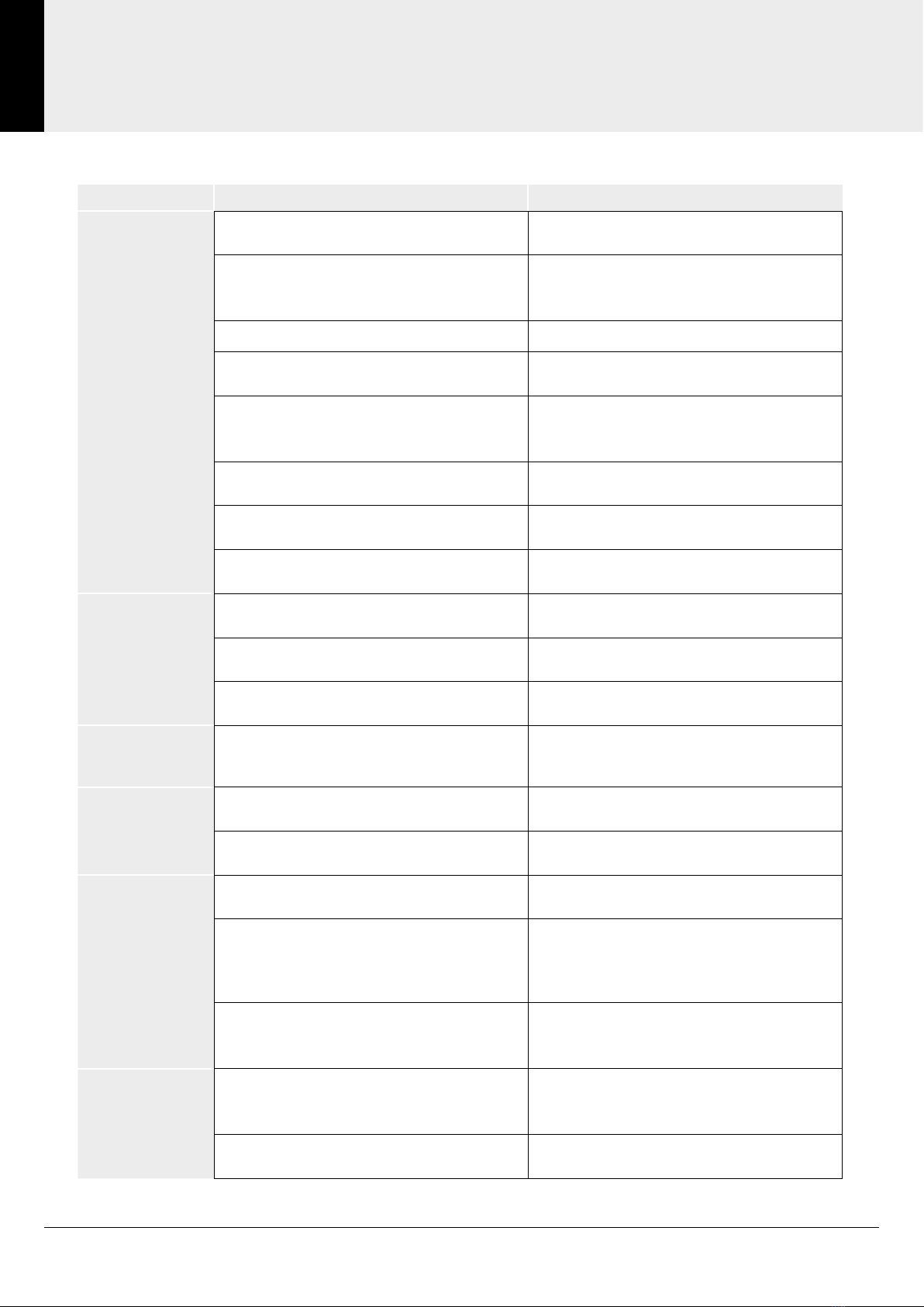
Problem Cause Solution
No flow or low
flow rate and
/ or varying
temperatures
Partially closed stop or service valve in
water supply pipework to the mixer valve. One stop or service valve.
Instantaneous water heater cycles on and
off as the flow rate or pressure is too low.
Increase water flow rate
or pressure through system.
Contact the boiler manufacturer.
Head of water is below the minimum required Refer to specifications section.
Inlet filter is partially blocked. Clean or replace. Flush pipework
before refitting.
Hot or cold water being drawn off
elsewhere causing pressure changes
or instantaneous boiler changes.
Do not use other water outlets when using
the shower valve.
Imbalanced inlet pressures. If pressures are unbalanced a pressure
reducing valve should be used.
Airblock or partial blockage of the pipework. Flush pipework to ensure removal
of debris and any airlocks.
No hot or cold water reaching
the shower valve.
Check hot and cold feeds (the valve will
shut down if either supply fails.
Water leaking
from shower
head
This is normal for a short time
after turning off.
Adjust the angle of the shower head as
necessary to vary draining time.
Shower flow control valve failing to close
fully, possibly due to water borne debris.
Remove flow control valve
assembly and check.
Flow control valve seals damaged. Check condition of flow control valve
and replace as necessary.
Maximum water
temperature is
too hot or cold
Maximum water temperature
is set incorrectly Reset maximum water temperature.
Outlet water
temperature is
too hot or cold
Inlet filter is partially blocked. Check inlet filters for any blockages
and clean as necessary.
Installation conditions are outside
operating parameters. Refer to Important Information section.
Water supply
temperature is
too cold
Hot water temperature is less than 10 °C
above the required blend temperature.
Adjust hot water temperature or wait for
water to reheat if stored system is used.
Instantaneous water heater is not igniting
because water flow rate is too low.
Increase water flow rate through the system.
Check cartridge inlet filters
and clean or replace.
Contact the manufacturer.
Instantaneous water heater is not igniting
because water pressure is too low.
Refer to Information for system requirements.
Increase water pressure through system.
Contact the manufacturer.
Only hot or cold
water from
TMV outlet.
Inlet water supplies are reversed (hot to
cold supply).
Connect the water supplies correctly. Hot on
the left and cold on the right when viewed
from the front. Rework pipework as necessary.
Inlet filter is partially blocked. Clean or replace. Flush through
pipework before refitting.

Technical Support: 01905 560 219 9Order: 01905 823 299 |orders.akw-ltd.co.uk
9
NOTES
Notes

General: 01905 823 298 | www.akw-ltd.co.uk10
10
NOTES
Notes

Technical Support: 01905 560 219 11Order: 01905 823 299 |orders.akw-ltd.co.uk
11
NOTES
Notes

© AKW Medi-Care Limited 2022 15-029-022-05
Contact Us
Orders & Quotes
01905 823 299
General Enquiries
01905 823 298
Technical Enquiries
01905 560 219
Kitchen Enquiries
01905 823 262
Fax
01905 823 297
AKW
Pointon Way, Hampton Lovett
Droitwich Spa, WR9 0LR
www.akw-ltd.co.uk
orders.akw-ltd.co.uk
Follow us on Social:
Warranty
Warranty applies only to manufacturing or material
defects, conditional on the one-time correct installation of
the product. It does not apply to:
• Inappropriate use or accidental damage.
• Damage or defects that result from incorrect installation.
• Lack of maintenance including the build up of grime or
damage resulting from inappropriate cleaning.
• Damage or defects that result from repairs or
modications undertaken by unauthorised persons.
• General wear and tear through usage and does not
apply to surface nishes.
Warranty period starts from the date of installation.
To activate your warranty, you must register your product
within 30 days of installation. See the T&Cs on our website
for further information.
Select 1 of 3 ways to activate your warranty
1. Scan using your Smart Device
2. Visit Online
akw-ltd.co.uk/warranty-information
3. Warranty Card
Fill and complete warranty card and post
using the prepaid envelope supplied
What to do if something goes wrong?
In the event that you encounter a problem with this
product, follow the trouble shooting guide if applicable,
then contact your local installer. If the issue is still
unresolved, contact AKW Technical Enquiries who will
provide further advice and arrange for a maintenance
engineer to visit if necessary. None of the foregoing
affects your statutory rights.
Table of contents
Other Akw Plumbing Product manuals

Akw
Akw Braddan 16472W Installation guide

Akw
Akw MediCare Installation guide

Akw
Akw Onyx Installation guide

Akw
Akw Luda User manual

Akw
Akw Larenco User manual

Akw
Akw Stone Wash Basin Service manual

Akw
Akw Onyx Toilet Roll Holder User manual

Akw
Akw M DigiPumps Series User manual

Akw
Akw PW90 User manual

Akw
Akw Onyx Linea AKW23980WH User manual