manuals.online logo
Brands
  1. Home
  2. •
  3. Brands
  4. •
  5. Akw
  6. •
  7. Plumbing Product
  8. •
  9. Akw Braddan 16472W Installation guide

Akw Braddan 16472W Installation guide

Braddan Shower Tray
Installation And User Care Instructions
Failure to install this AKW product in accordance with supplied instructions or the making of unauthorised modifications will
invalidate any warranty and will affect product safety.
AKW, Pointon Way, Hampton Lovett, Droitwich Spa, WR9 0LR
Tel.+44 (0) 1905 823298 - Fax. +44 (0) 1905 823297 - www.akw-ltd.co.uk
© 2018 AKW 01-018-200-09
To order additional products or parts please call: 01905 823299 or on the details above
Read ALL instructions carefully BEFORE installation and leave with the end user
Sizes Avaliable
Place ramp onto a level floor and
against tray, ensure ramp is flush
with tray edge and in
appropriate position. Mark off
fixing holes, drill and insert
suitable fixings in the floor.
Apply silicone sealant to contact
area of ramp before fixing with
No.8 x 38mm (11/2”) pan head self
tapping screws. Snap in
plastic sections to close fixing
cavity and place end caps to ramp
using adhesive. Note: For ramps
that continue around corner of
tray, a 45º joining piece is
supplied. These ramps may
require cutting to size. Ensure
that silicone is applied between
joining piece and tray and joining
piece and ramp.
(See Figs. 11, 12 and 13).
Guaranteed
for
Life
Fig.13
45º joining piece
Step 4 - Braddan Ramps
800x800 820x820 900x900 1000x700 1000x800
1000x1000 1200x650 1200x700 1200x760 1200x820
1200x900 1300x700 1300x820 1420x700 1420x820
1500x700 1500x820 1700x700 1800x700 1800x820
Installation
IMPORTANT
Before completing the installation, water test the flow from tray into waste for correct installation and drainage efficiency.
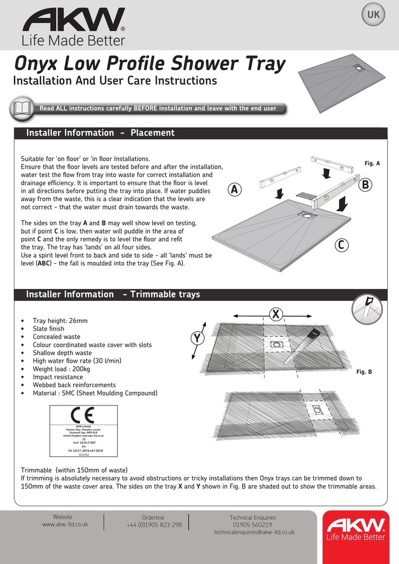
It is important to ensure that the floor is level in all directions before putting the tray into place. If water puddles away from
the waste, this is a clear indication that the levels are not correct - the water is acting as a ‘spirit level’.
The sides on the tray A and Bmay well show level on testing, but if point Cis low, then water will puddle in the area of point C
and the only remedy is to level the floor and refit the tray. The tray has ‘lands’ on all four sides.
Use a spirit level front to back and side to side - all ‘lands’ must be level (ABC) - the fall is moulded into the tray (See Fig. A).
It is not necessary to remove plaster from the walls for installing the above trays. When tiling, ensure that the bottom row of
tiles are bedded in to align with the final position of the tray.
Fig. A
The Braddan Shower Tray should be cleaned periodically to remove any accumulation of hair or other waste material, using
normal domestic bathroom cleaning materials. Do not use strong or concentrated acidic, alkaline or other cleaning materials as
these may damage or discolour the product. After cleaning always flush down with water then wipe thoroughly with a damp
cloth to remove any cleaning material residues before drying off.
Available Sizes (mm)
Usercare Instructions
End Cap
Silicon Seal
Snap in
Vinyl Flooring
Flush
Fig. 11
Fig.12
UK
UK
UK
UK
5mm
4mm
3mm
AB
C
Technical Help line 01905 560219
Technical Help line
01905 560219
Orderline
01905 823299
General Enquiries
01905 823298
Fax
01905 823297
Website
www.akw-ltd.co.uk
Quotes & orders email
[email protected]
Enquiries email
[email protected]
[email protected]
Contact
ALL GRP TRAYS
Label for
Product
Packaging
Manual
Note
DoP numbers are
Braddan
Tri-form
09-012-075
GRP Braddan
01-018-330
Sulby
01-018-331
Sulby 2
01-018-332
Multi Spec
01-018-333
Low Profile
01-018-334
DoP 01-018-330
07-003-050
DoP
DoP 01-018-330-02
07-003-050-02
DoP
AKW Limited
Pointon Way, Hampton Lovett
Droitwich Spa, WR9 0LR
United Kingdom
www.akw-ltd.co.uk
AKW Limited
Pointon Way, Hampton Lovett,
Droitwich Spa, WR9 0LR
United Kingdom
www.akw-ltd.co.uk
DoP 01-018-330-02
07-003-050-02DoP
For latest AKW news and
products, scan this code
with your phone or tab
device.
300mm MAX Cut down length
See Instructions 07-003-020 for more information on Cut-to-length.
The Braddan 1800 tray has a cut to length area that can be cut to suit the dimension between walls down to 1500mm.
Use a fine toothed blade in either jigsaw or handsaw (cut from below with jigsaw or from above with handsaw).
Allow for thickness of trim angle ‘B’ (2mm or 1/8”) when cutting tray to size (See Fig. 10).
After trimming tray and angles A & B to size, mastic underside of tray in position of angle ‘B’ placement. Fit angle ‘B’ to
underside of tray with stainless steel screws. Place tray onto a prepared level floor and between walls, ensuring that angle
‘B’ is tight against end wall. Place angle ‘A’ onto tray and against angle ‘B’ then drill 4.5mm (3/16”) diameter holes on ‘v’ groove
location through both angles (drill countersunk holes in angle ‘A’). Remove angle ‘A’ then drill through previously drilled holes in
angle ‘B’ with a No.10 / 5mm masonry drill into wall and fit plastic wall plugs. Silicone seal undersides of angle
‘A’ then fix to wall with No. 8x38mm (11/2”) countersunk head stainless steel screws. Silicone seal between angle ‘A’ and tray if
required. If required the trimmed tray edge is now ready for end moulding. (See cut-to-length instructions 07-003-020).
Step 3 - Cutting 1800mm Tray to length
Fig. 10
No.8 x 13mm
(1/2”) Pan Head
Screws
Angle A
Angle B
4.5mm (3/16”)
dia. holes
No.8 x 38mm
(11/2”)
Countersunk
Screws
Step 1 - Tiling UpstandStep 1- Tilling Upstand
N.B.Tiling upstands are supplied cut-to-size. Installers to drill holes for tray fixings.
Tiling upstand (fixing flange to tray) may have to be cut out to accommodate waste pipe exit in tray before fixing to tray.
Place tiling upstand against tray wall edges, ensure that upstand has angled ribbed face against tray wall and is flush with top
of tray edge and is correctly positioned at corner before marking off fixing holes.
Drill 3.5mm (1/8”) diameter holes in tray, apply silicone sealant to tiling upstand before affixing to tray with No. 8 x 20mm (3/4”)
pan head self tapping screws.
Fit other tiling upstand in the same way, ensuring that it butts up to and is level with previously installed upstand at corner.
Cavities caused by radius on tray edge and corner must be silicone sealed (See Fig. 1, Fig. 2 and Fig. 3).
Fig. 1 Fig. 2 Fig.3
Silicone Sealant
No.8x20mm
pan head self tapping screws
Tiling Upstand
3.5mm dia. hole
Tiling Upstand
Silicone Sealant
Option 3- Installing Tray To Wooden Floor
Place tray onto floor with tiling upstands tight against plaster finish on back walls. Mark around tray front edges onto floor then
cut along marked line and remove floor boarding. Install 75 x 50mm (3” x 2”) wood noggins to joists around floor recess edges as
shown. Note: These noggins must be installed level for tray to sit level when placed into floor recess. This will ensure that fall in
tray will efficiently drain to waste.
Fig. 8
Install the waste into the tray and connect the exit pipes to the waste. Place tray into
floor recess ensuring that the tray edges are tight up to edges of previously cut
floorboard. Drill for suitable plugs in wall for tiling upstand fixings then fix with CSK
head stainless steel screws (not supplied). Re-check tray is level and test for water
drainage efficiency of tray. Apply mastic to tiling upstand while tiling bottom row of tiles.
(See Fig. 8). Vinyl floor covering should finish flush to and be level with ramp edge as
shown. If the waste pipes have to pass through the wooden floor joists, these should be
drilled and not notched. Preferably drilled close to the centre of the joist. (See Fig. 9)
Wood
Waste Joist
Wall
Option 2- Installing Tray On Top Of Floor
Place waste outlet to tray and exit pipes to waste outlet.
Place tray on top of floor with tiling upstands tight against plaster finish on back walls, ensure tray is level
in all directions.
Fig. 7
When tiling upstands are tight against back walls, drill for suitable plugs in wall, then fix with CSK head stainless steel screws
(not supplied). Re-check tray is level and water test before tiling. Apply mastic to tiling upstand, while fitting bottom row
of tiles as shown. When using a 40mm (11/2”) ramp, install vinyl tiles up to and level with ramp edge. If not using a 40mm
(11/2”) ramp, install vinyl or tiles up to tray edge.
40mm Ramp
Wall
Option 1- Installing Flush With Screed Fig. 5
Correct
Incorrect
Fig. 9
75x50mm
Noggins
Vinyl
Wall
Screed
Plaster
Mastic
Plaster
Mastic
Plaster
Mastic
Vinyl
Vinyl
Place tray onto screed with tiling upstands tight against plaster finish on back walls.
Mark around tray front edges onto screed, then cut along marked line using a suitable
cutting disc to remove screed. Ensure that prepared recess is level in all directions.
Fit waste outlet to tray and exit pipes to waste outlet. A gravity type waste is preferred
but a pumped waste can be installed using a standard pumped waste unit or a special
uplift waste. The waste pipe is concealed in the tray and can exit through the tray edge
at the required position. (See Fig. 5)
Note. The uplift pump waste option needs to be ordered as a factory fitted item with tray.
(See Fig. 6)
However, the standard tray can accommodate a pump waste manifold under the tray using
a Shower Waste Pump.
Once the uplift waste adaptor direction has been set and outlet pipe work fitted, check
locking collars are in place.
Mask edges of tray with masking tape to avoid scratching and place tray into floor
recess, ensure that tiling upstands are tight against plaster on back walls.
Important: Tray front edges should finish above the level of screed to
accommodate thickness of floor tiles being used ie. vinyl, tiles, etc.
Fig. 4
Fig. 6
Adaptor
Locking Collars
Technical Help line 01905 560219

Other Akw Plumbing Product manuals

Akw Onyx Installation guide

Akw

Akw Onyx Installation guide

Akw AKW23196CH Quick start guide

Akw

Akw AKW23196CH Quick start guide

Akw M DigiPumps Series User manual

Akw

Akw M DigiPumps Series User manual

Akw PW90 User manual

Akw

Akw PW90 User manual

Akw MediCare Installation guide

Akw

Akw MediCare Installation guide

Akw Larenco User manual

Akw

Akw Larenco User manual

Akw GW90 User manual

Akw

Akw GW90 User manual

Akw Itherm Quick guide

Akw

Akw Itherm Quick guide

Akw Luda User manual

Akw

Akw Luda User manual

Akw Option P User manual

Akw

Akw Option P User manual

Akw SMV-001 Guide

Akw

Akw SMV-001 Guide

Akw Onyx Linea AKW23980WH User manual

Akw

Akw Onyx Linea AKW23980WH User manual

Akw iSure Quick guide

Akw

Akw iSure Quick guide

Akw T301 User guide

Akw

Akw T301 User guide

Akw Stone Wash Basin Service manual

Akw

Akw Stone Wash Basin Service manual

Akw iTherm 30306 User manual

Akw

Akw iTherm 30306 User manual

Akw Arka Thermostatic Cool Touch TMV2 User manual

Akw

Akw Arka Thermostatic Cool Touch TMV2 User manual

Akw Onyx Toilet Roll Holder User manual

Akw

Akw Onyx Toilet Roll Holder User manual

Popular Plumbing Product manuals by other brands

Bradley Express SS-2N/AST/STD Installation

Bradley

Bradley Express SS-2N/AST/STD Installation

Brizo VENUTO manual

Brizo

Brizo VENUTO manual

Sanela SLUN 54 Mounting instructions

Sanela

Sanela SLUN 54 Mounting instructions

Moen BGCW10RV1618 installation guide

Moen

Moen BGCW10RV1618 installation guide

Luxart AERRO A711FMTO installation manual

Luxart

Luxart AERRO A711FMTO installation manual

Signature Hardware MEDFORD 946810 manual

Signature Hardware

Signature Hardware MEDFORD 946810 manual

Kohler K-8816 installation guide

Kohler

Kohler K-8816 installation guide

Kohler K-6448 Homeowner's guide

Kohler

Kohler K-6448 Homeowner's guide

Zanussi 132455 Specifications

Zanussi

Zanussi 132455 Specifications

Gerber C0-44-551 Installation

Gerber

Gerber C0-44-551 Installation

Laufen ILBAGNOALESSI One 8.1197.1 installation instructions

Laufen

Laufen ILBAGNOALESSI One 8.1197.1 installation instructions

Grohe GROHTHERM 2000 34 174 instructions

Grohe

Grohe GROHTHERM 2000 34 174 instructions

T&S B-0315-LN Installation and maintenance instructions

T&S

T&S B-0315-LN Installation and maintenance instructions

Gessi VIA MANZONI 38731 manual

Gessi

Gessi VIA MANZONI 38731 manual

SUMS uridan ADMIRAL GH-10 installation instructions

SUMS

SUMS uridan ADMIRAL GH-10 installation instructions

VIGO VG08004 manual

VIGO

VIGO VG08004 manual

Kohler BADRON K-5487T-B installation instructions

Kohler

Kohler BADRON K-5487T-B installation instructions

BATHSELECT BST-008-1ORB installation instructions

BATHSELECT

BATHSELECT BST-008-1ORB installation instructions

manuals.online logo
manuals.online logoBrands
  • About & Mission
  • Contact us
  • Privacy Policy
  • Terms and Conditions

Copyright 2025 Manuals.Online. All Rights Reserved.