Albixon LED-P100 User manual

POOL LIGHT LED-P100
(12V/8W)
INSTALLATION
AND
USER GUIDE
EN
DE
FR
ES
RU
CZ
PL
SE
IT
i
Please, carefully read the instruction

Installation
and user guide ..........................................................................3
Installations-
und Bedienungsanleitung.........................................................9
Manuel d‘installation
et d‘utilisation ........................................................................15
Manual
de instalación y de uso ...........................................................21
Монтажное руководство
ируководство по эксплуатации .........................................27
Instalační
a uživatelská příručka ...........................................................33
Podręcznik
instalacji i użytkowania .........................................................39
Installations
och bruksanvisning ................................................................45
DE
FR
ES
RU
CZ
PL
SE
Manuale
di installazione ed uso............................................................51
IT
EN

3
1. Preparation steps that must be taken by an
electrician before the light installation: See picture 1.
1. Make sure that the electric system and its installation meet the requirement of your governmental or local
bodies. The installation of the underwater light can be operated only by a qualified electrician.
a) The junction box of the low-voltage transformer for 12V model of the light must be placed at least
350 cm from the edge of the pool, see picture 1.
b) The light and all metal components placed 240 cm from the edge of the pool must be appropriately
protected by inflexible materials and the binds must be waterproofed.
c) The assembly consol must be properly installed in a way that the top edge of the light lentil is at least
45 cm under the pool water level, see picture 1.
TO THE POWER SUPPLY UNIT
CAST IN PARAFFIN
WATER LEVEL
INFLEXIBLE
INSTALLATION PIPE
MINIMUM 120 CM
29,6 CM
6,6 CM
MINIMUM 45CM FROM THE WATER
LEVEL TO THE TOP EDGE OF THE LENTIL
THE CONCRETE MUST BE
RECEDED AROUND THE
BAY IN ORDER TO CREATE
THE SPACE FOR THE COM-
PACTPADDING FROM THE
PLASTER.
Picture 1
EN

4
2. After meeting requirements for the electric system,
carry out the following steps
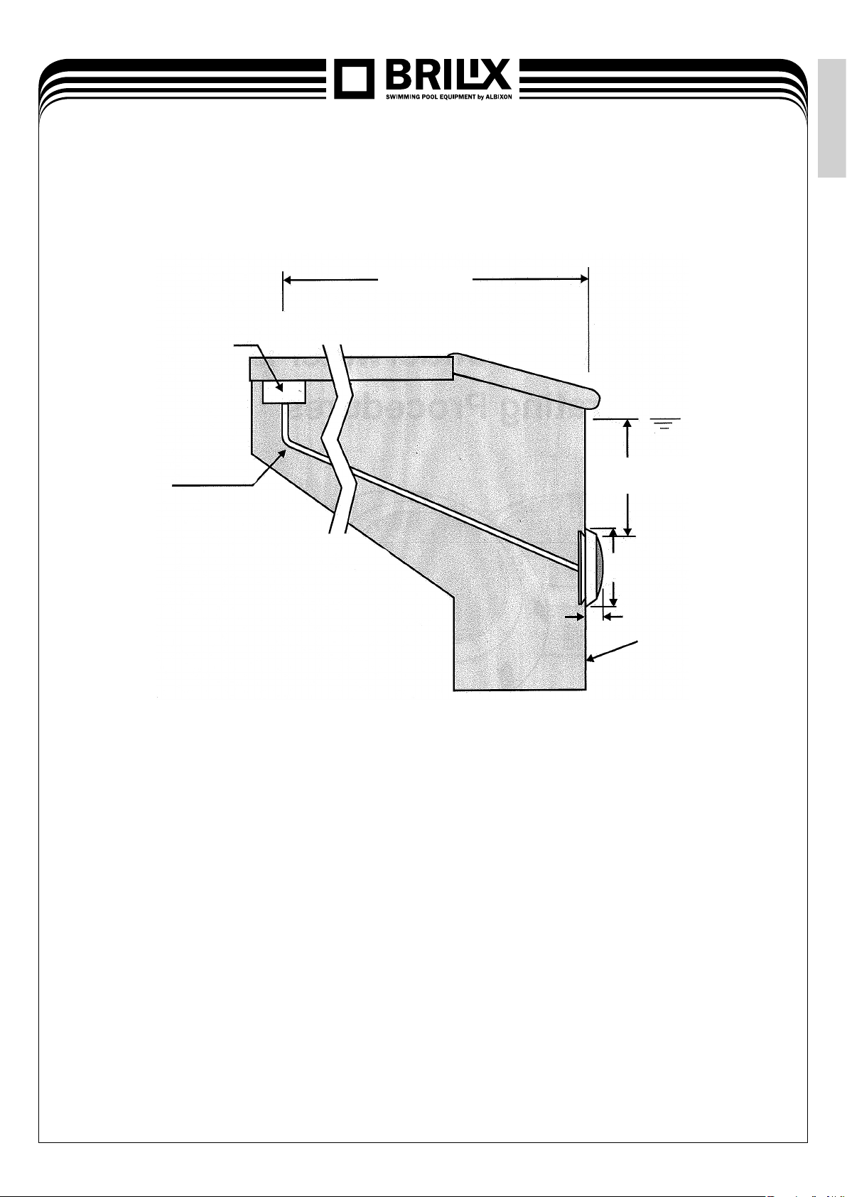
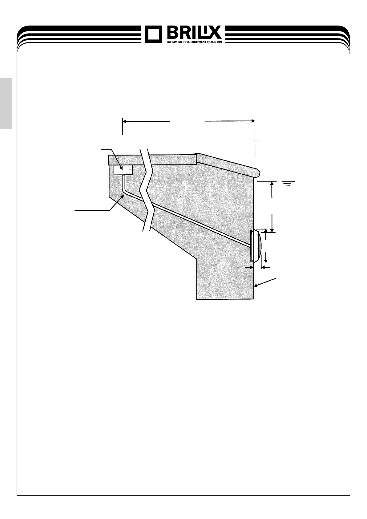
1. Find a place on the vertical surface where you want to install the light. The top edge of the lentil should
be placed 45cm under the pool water level, see picture 1.
2. Connect the installation pipe to the centre of the distant erection pack (left from the consol), see picture 2
3. If the surface of the pool should be plastered, you must leave the concrete receded of the thickness
of the plaster. Completed surface of the concrete must be levelled with the distant erection pack.
ATTENTION: Completed surface in the surroundings of the distant erection pack MUST BE flat and
aligned with the surface of the distant erection pack. It ensures the perfect adhesion of the light to the wall
of the pool, see picture 3.
4. After finishing the surface of the pool, trim the installation pipe.
5. Roll the electric cable up in a way that its available length does not exceed 2,4 m. This superfluous cable
enables to remove the light from the pool in order to exchange the lamp and carry out the service.
6. Pull the cable through the installation pipe and connect its conductors in the junction box. While connecting
the conductors be careful not to pull more than 75-80 mm of the superfluous cable on the light through the
installation pipe.
7. Connect all conductors to the appropriate circuit conductors in the junction box and pad all connections
by the use of paraffin.
8. Fix the cover of the junction box.
9. Before turning the light on for longer than 10 seconds, fill the pool in a way that the light will be completely
immersed in the water. In order to check the correct functions, turn the main switch or the fuse on, also
activate the switch controlling the appropriate light.
10. The safe installation of the light to the consol is secured by turning the safety system, see picture 4.
11. The light must be connected to the safety transformer for 12V
EN

5
3. Preparation for winter:
the light should remain in place during the winter
Picture 2 Picture 3
ASSEMBLY CONSOL
LIGHT
INSTALLATION
PIPE
DO NOT ASSEMBLE ON ASSEMBLE ON
SURFACEWITH
INVERSED RADIUS
IRREGULAR OR
UNEQUAL SURFACES
FLAT
SURFACE
Picture 4
OPEN POSITION SECURED POSITION
EN
WALLS WITH A RADIUSTHAT IS NOT
SMALLERTHAN 1,83 M WHILE OBSERVING
FROMTHE ABOVE LEVEL

6
4. List of components
Position Amount Description
11screw
21frontring
31cover
41lentil
51lentilpadding
6 3 screw
71bulbdesk
8 1 head with a cut
91sealingO-ring
10 1 body
11 8screw
8nut
12 4 screw
13 1 lamp holder
14 1 consol for fitting to the wall
15 1 cable
16 2 isolating connectors to the clamps
17 2 isolating connectors to the clamps
EN

7
Conditions of guarantee
Conditions of guarantee abide by the trading and guarantee conditions of your supplier.
Secure disposal of the product after the lifetime expiry
After the lifetime expiry, ensure its ecologic disposal made by a skilled company
Complaints and customer service
Complaints abide appropriate consumer protection rights. In the event of unrecoverable effect
please, address the written complaint to your supplier.
Date................................................................
Supplier
EN

8
WARNING
Never use this light for longer than 10 seconds if it isn’t completely immersed under the water.
In case, the assembled light will not be completely immersed, it will heat up considerably which can
cause a serious injury to the users of the pool, plumbers and passers-by, or can deteriorate assets.
DANGER!
THE RISK OF BEING STROKEN OR KILLED BY THE ELECTRIC CURRENT
Thislightmust beinstalledbyaqualiedelectricianor aqualiedserviceengineerinconformitywith
standards introduced by your governmental or local bodies. Incorrect installation creates electric
danger that might lead to the serious injury, death or it might deteriorate assets. Before starting
the service work on the light, disconnect the current from its supply. If you do not follow this
instruction you might be exposed to the risk of a serious injury, death or deterioration of assets.
EN

9
SCHWIMMBECKENSCHEINWERFER LED-P100
(12V/8W)
INSTALLATIONS-
UND
BEDIENUNGSANLEITUNG
DE
i
Lesen Sie die Bedienungsanleitung

10
1.
Vorbereitungsschritte, die der Elektriker vor der
Beleuchtungsinstallation durchzuführen hat: siehe Abb. 1
1. Es ist sicherzustellen, dass das elektrische System und seine Installation für das Schwimmbecken den
Anforderungen der staatlichen oder örtlichen Behörden entsprechen. Die Installation der Beleuchtung
darf nur ein qualifizierter Elektriker durchführen.
a) Der Anschlusskasten oder der Niederspannungstransformator für das 12V-Scheinwerfermodell muss
mindestens 350 cm vom Schwimmbeckenrand entfernt sein, siehe Abb. 1.
b) Der Scheinwerfer und alle Metallteile, die sich in einer Entfernung von bis zu 240 cm vom
Schwimmbeckenrand befinden, müssen durch nicht flexible Materialien entsprechend geschützt
werden und die Verbindungen müssen wasserdicht sein.
c) Die Montagekonsole muss ordnungsgemäß installiert werden, so dass der obere Rand der Beleuchtungslinse
mindestens 45 cm unter dem Wasserspiegel im Schwimmbecken liegt, siehe Abb. 1.
ZUR EINSPEISUNGSQUELLE
MIT PARAFIN EINGIESSEN
WASSERSPIEGEL
NICHT FLEXIBLES
INSTALLATIONSROHR
120 CM MIN.
29,6 CM
6,6 CM
MIN. 45 CM VOM WASSERSPIEGEL ZUM
OBEREN LINSENRAND
DER BETON MUSS RUND
UM DIE NISCHE ETWA
ZURÜCKLIEGEN, SO DASS ES
PLATZ FÜR DIE KOMPAKTE
DICHTUNG AUS PUTZ GIBT.
Abbildung 1
DE

11
2. Nach der Erfüllung der Anforderungen an das
elektrische System führen Sie die folgenden
Schritte durch
1. An einer senkrechten Wand finden Sie die Stelle, wo die Beleuchtung installiert werden soll. Der obere
Rand der Beleuchtungslinse muss 45 cm unter dem normalen Wasserspiegel liegen, siehe Abb. 1.
2. Das Installationsrohr schließen Sie an der Mitte der Montage-Distanzunterlage (links von der Konsole)
an, siehe Abb. 2.
3. Soll die Schwimmbeckenoberfläche verputzt werden, muss der Beton um die Putzdicke zurückliegen. Die
beendete Betonoberfläche muss mit der Montage-Distanzunterlage in einer geraden Linie liegen.
VORSICHT: Die beendete Oberfläche in der Umgebung der Montage-Distanzunterlage MUSS glatt
und mit der Oberfläche der Montage-Distanzunterlage in einer Linie liegen. Das sichert das einwandfreie
Anliegen der Beleuchtung an die Wand, siehe Abb. 3.
4. Am Rande der Schwimmbeckenoberfläche schneiden Sie das Installationsrohr zurück.
5. Das Elektrokabel ist so einzuwickeln, dass seine freie Länge 2,4 m nicht überschreitet. Diese zusätzliche
Kabellänge ermöglicht das Herausnehmen des Scheinwerfers aus dem Schwimmbecken, um das
Leuchtmittel auszutauschen und den Service durchzuführen.
6. Ziehen Sie das Kabel durch das Installationsrohr durch und schließen Sie seine Leiter im Anschlusskasten
an. Beim Anschließen der Leiter beachten Sie, dass Sie durch das Installationsrohr nicht mehr als 75–80
mm des freien Kabels in den Scheinwerfer einziehen.
7. Schließen Sie alle Leiter an die entsprechenden Stromkreisleiter im Verbindungskasten an und die
Verbindungen dichten Sie mit Paraffin ab.
8. Befestigen Sie den Deckel des Verbindungskastens.
9. Bevor Sie das Licht für eine Zeit von mehr als 10 Sekunden einschalten, füllen Sie das Schwimmbecken
so, dass die Beleuchtung vollständig mit Wasser bedeckt ist. Zur Überprüfung der ordnungsgemäßen
Funktion schalten Sie den Hauptschalter oder Schutzschalter sowie den Schalter, mit dem die eigentliche
Beleuchtung gesteuert wird, ein.
10. Die sichere Befestigung des Scheinwerfers an der Konsole wird durch das Drehen des Sicherheitssystems
garantiert, siehe Abb. 4.
11. Die Beleuchtung muss an einen 12V – Sicherheitstransformator angeschlossen werden.
DE

12
3. Einwinterung:
Die Beleuchtung muss man vor Ort belassen.
Abbildung 2 Abbildung 3
MONTAGEKONSOLE
SCHEINWERFER
INSTALLA-
TIONSROHR
KEINE MONTAGE AUF MONTAGE AUF
OBERFLÄCHE MIT
UMGEKEHRTEM RADIUS
UNREGELMÄSSIGE
ODER NICHT GLATTE
OBERFLÄCHEN
EBENE
OBERFLÄCHE
Abbildung 4
GEÖFFNETE POSITION GESICHERTE POSITION
DE
OBERFLÄCHEN MIT EINEM RADIUS,
DER BEIM BLICKVON OBEN NICHT
WENIGER ALS 1,83 M BETRÄGT

13
4. Verzeichnis der Teile
Position Menge Beschreibung
11Schraube
21Frontring
3 1 Abdeckung
41Linse
51Linsendichtung
63Schrauben
71Glühbirnenplatte
8 1 Kopf mit Einkerbung
91O-Ring
10 1 Gehäuse
11 8Schrauben
8Muttern
12 4 Schrauben
13 1 Scheinwerferhalter
14 1 Konsole für die Wandmontage
15 1 Kabel
16 2 isolierte Zuleitungen zu Klemmen
17 2 isolierte Zuleitungen zu Klemmen
DE

14
WARNUNG
Benutzen Sie diese Beleuchtung nie für eine Zeit von mehr als 10 Sekunden, solange sie
nicht vollständig mit Wasser bedeckt ist. Wenn die zusammengestellte Beleuchtung nicht
vollständig eingetaucht ist, wird sie enorm heiß, was zu schwerwiegenden Verletzungen der
Schwimmbeckenbenutzer, Installateure oder vorbeigehenden Personen oder zu Schachschaden
führen kann.
GEFAHR!
STROMSCHLAG ODER LEBENSGEFAHR DURCH ELEKTRISCHEN STROM
Diese Beleuchtung muss ein qualizierter Elektriker oder qualizierter Servicemitarbeiter in
Übereinstimmung mit den Anforderungen der staatlichen Auagen bzw. der örtlichen Behörden
installieren. Eine nicht korrekte Installation ist eine Gefahrenquelle, die zu schwerwiegenden
Verletzungen;TododerSachschadenführenkönnte.BevorSieReparaturarbeitenanderBeleuchtung
vornehmen,trennenSiedie EinspeisungvomSchutzschalter. DieNichteinhaltungdieserAnweisung
könnte schwerwiegende Verletzungen; Tod oder Sachschaden verursachen.
Garantiebedingungen
Die Garantiebedingungen richten sich nach den Geschäfts- und Garantiebedingungen Ihres Zulieferers.
Sichere Entsorgung des Produkts nach der Beendigung der Betriebsdauer
Nach der Beendigung der Betriebsdauer des Produktes sichern Sie seine fachgerechte ökologische
Entsorgung durch eine Fachfirma.
Reklamationen und Service
Die Reklamationen richten sich nach den entsprechenden Verbraucherschutzgesetzen. Beim Feststellen
eines unbehebbaren Fehlers wenden Sie sich schriftlich an Ihren Lieferanten.
Datum................................................................
Lieferant
DE

15
ECLAIRAGE PISCINE LED-P100
(12V/8W)
MANUEL D’INSTALLATION
ET
D’UTILISATION
FR
i
Veuillez lire le mode d‘emploi

16
1. Les démarches préparatoires à réaliser par un
électricien avant d’installer l’éclairage: voir figure 1.
1. Le système d’électricité et l’installation dans la piscine doivent être conformes aux exigences de votre
gouvernement ou des autorités locales. L’installation de l’éclairage doit être réalisée par un électricien
qualifié.
a) a) La boîte de connexion ou le transformateur basse tension pour le modèle d’éclairage de 12V doivent
être installés au moins à 350 cm du bord de la piscine, voir figure 1.
b) L’appareil d’éclairage et toutes les parties en métal, qui se trouvent à moins de 240 cm du bord
de la piscine, doivent être convenablement protégées par des matériaux inflexibles et les joints doivent
être étanches.
c) La console de montage doit être proprement installée de manière que le bord supérieur de la lentille
de l’éclairage soit au moins à 45 cm au dessous de niveau d’eau dans la piscine, voir figure 1.
A LA SOURCE D´ALIMENTATION
SCELLEZ AVEC DE LA PARAFFINE
LE NIVEAU D’EAU
LE TUBE D
´INSTALLATION
INFLEXIBLE
120 CM MIN.
29,6 CM
6,6 CM
AU MOINS 45 CM DE NIVEAU D’EAU AU
BORD SUPÉRIEUR DE LA LENTILLE
LA NICHE DOIT ÊTRE
ÉLOIGNÉ POUR FAIRE
PLACE À LA GARNITURE
COMPACTE DE L’ENDUIT.
Figure 1
FR

17
2. Pour remplir les exigences du système électrique,
effectuez les démarches suivantes
1. Trouvez une place sur le mur vertical pour installer l‘éclairage. Le bord supérieur de la lentille de
l’éclairage doit être à 45 cm sous le niveau d’eau normal, voir figure 1.
2. Attachez le tube d’installation au centre du support d’écartement de montage (à gauche de la console),
voir figure 2.
3. Si la piscine doit être ravalée, vous devez faire éloigner le béton à l’épaisseur de l’enduit. La surface du
béton doit être de niveau avec le support d’écartement de montage.
ATTENTION: La surface finie autour du support d’écartement de montage DOIT être lisse et de niveau
avec la surface du support d’écartement. Ceci assure une adhérence parfaite de l’éclairage au mur, voir
figure 3.
4. Après avoir terminé la surface de la piscine, taillez le tube d’installation.
5. Enroulez le câble de manière que sa longueur libre ne dépasse pas 2,4 m. Ce câble excédentaire permet
d’enlever l’éclairage de la piscine pour des raisons de remplacement de la lampe et de service.
6. Faites passer le câble par le tube d’installation et connectez ses fils conducteurs à la boîte de connexion.
Faites attention à ne pas faire traverser plus que 75–80 mm du câble libre par le tube d’installation pendant
la connexion des fils conducteurs,
7. Connectez tous les fils conducteurs aux fils conducteurs de circuit dans la boîte de connexion et obturez
les joints avec de la paraffine.
8. Fixez le capot de la boîte de connexion.
9. Avant d’allumer l’éclairage pour plus que 10 secondes, remplissez la piscine pour que l‘éclairage soit
entièrement au dessous de l’eau. Pour vérifier le fonctionnement correct, allumez l’interrupteur principal
ou le coupe-circuit automatique et aussi l’interrupteur de l’éclairage lui-même.
10. Une fixation sûre de l’éclairage à la console est assurée par le tour de système de sécurité, voir figure 4.
11. L’éclairage doit être connecté au transformateur de sécurité pour 12V.
FR

18
3. Hivernage:
pendant l’hiver l’éclairage doit rester à sa place
Figure 2 Figure 3
CONSOLE DE MONTAGE
ECLAIRAGE
TUYAU D
INSTALLATION
NE MONTEZ PAS SUR MONTEZ SUR
UNE SURFACE AU
RAYON INVERSE
LES SURFACES
IRREGULIÈRES OU
RUGUEUSES
LA SURFACE
LISSE
MURES AVEC RAYON PLUS
PETIT QUE 1,83 VU DE HAUT
Figure 4
POSITION DÉBLOQUÉE POSITION BLOQUÉE
FR

19
4. Liste des composants
Position Quantité Description
11vis
2 1 anneau frontal
31capot
4 1 lentille
5 1 joint de lentille
63vis
71plaqued’ampoule
8 1 tête avec encoche
9 1 anneau O d‘étancheité
10 1 le corps
11 8vis
8ecrou
12 4 vis
13 1 porte-lampe
14 1 console pour la fixation au mur
15 1 câble
16 2 arrivées étanches aux bornes
17 2 arrivées étanches aux bornes
FR

20
AVERTISSEMENT
N’utilisez jamais cet éclairage pour plus que 10 secondes, s’il n’est pas entièrement au
dessous de l’eau. Si l’éclairage assemblé n’est pas entièrement au dessous de l’eau, il chaue
considérablement, ce qui peut causer de graves blessures aux utilisateurs de la piscine, aux
plombiers, aux passants ou endommager des biens.
DANGER!
DANGER D‘ATTEINTE OU DE MORT CAUSE PAR LE COURANT ELECTRIQUE
Cet éclairage doit être installé par un électricien qualié ou par un employé de service compétent,
conformément aux exigences de normes de votre pays ou des autorités locales. Une installation
incorrecte crée les dangers électriques qui peuvent causer une grave blessure, mort ou
endommagement des biens. Avant de commencer le service de votre éclairage, déconnectez
l’alimentation de l’interrupteur. Non respect de cette instruction peut causer une grave blessure,
mort ou endommagement des biens.
Conditions de garantie
Les conditions de garantie sont soumises aux conditions de vente et de garantie de votre fournisseur.
Liquidation sûre de produit après sa durée de vie
A la fin de la durée de vie de votre produit, assurez une liquidation écologique réalisée par des professionnels.
Service après vente
La réclamation se conforme aux lois applicables sur la protection du consommateur. En cas de défaut
irréparable, veuillez contacter votre fournisseur par écrit.
La date................................................................
Fournisseur
FR
Other manuals for LED-P100
1
Table of contents
Languages:
Other Albixon Swimming Pool Lighting manuals
Popular Swimming Pool Lighting manuals by other brands

Astral Pool
Astral Pool 54092 Installation and maintenance manual

Pentair Pool Products
Pentair Pool Products SpaBrite Installation procedures

J&J Electronics
J&J Electronics PureWhite LPL-P1-WHT-12-S Installation and operation guide

Seamaid
Seamaid LedinPool 502860 Usage & Maintenance Manual

O'Ryan Industries
O'Ryan Industries PoolStar 3000 instructions

Gemas
Gemas SlimLED LIGHT Installation and maintenance manual