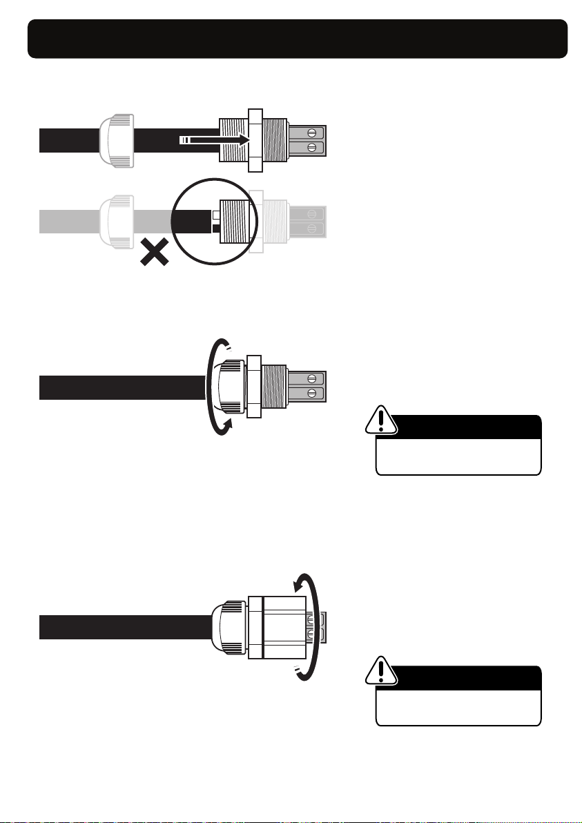
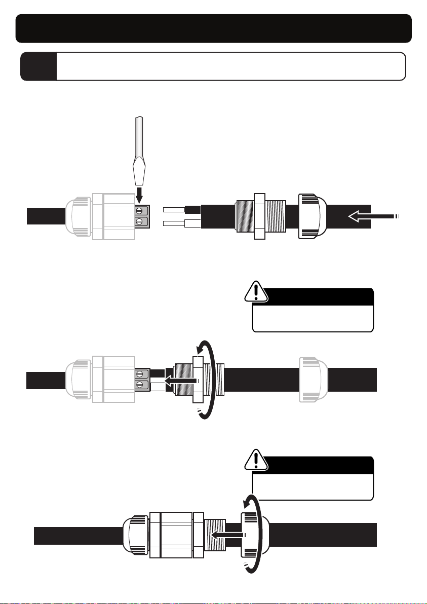
Spa Electrics RETRO Series Operating instructions
Other Spa Electrics Swimming Pool Lighting manuals


Popular Swimming Pool Lighting manuals by other brands

Pentair
Pentair INTELLIBRITE 5G LED LIGHT Quick reference guide

BEGA
BEGA 88 913 Instructions for use

Wibre
Wibre 4.0171 installation manual

emaux
emaux E-Lumen X TOPAZ Series Installation and operation manual

ENERGY FOCUS
ENERGY FOCUS Fiberstars Y20-6000 Procedure

Seamaid
Seamaid LEDINPOOL 502808 Installation & maintenance manual

Dot-Spot
Dot-Spot aquaros 5 Operator's manual

Bestway
Bestway ColorJet instructions

Astral Pool
Astral Pool DMX Installation, operation and maintenance manual

Royal Exclusiv
Royal Exclusiv RE-Light Operating and maintenance manual

PAL
PAL EVEN GLOW installation manual

Artecta
Artecta Meteor-175W operating instructions

Pentair
Pentair MAGICSTREAM LAMINAR Installation and user guide

Pentair
Pentair INTELLIBRITE 5G Installation and user guide

Pahlen
Pahlen 170VS user manual

Steinbach
Steinbach 060060 instructions

Hidrotermal
Hidrotermal HIDRO-SPOT60H Installation and maintenance manual

Pentair
Pentair INTELLIBRITE 5G Installation and user guide