Alcolizer WM4 User manual

REF: WM4 Service WI V18.docx Page 1 © Alcolizer Technology
Uncontrolled when printed
WM4 Service Work Instructions
Work Instruction
Di
Disclaimer –Internal Document note to reader
This document is intended for use within Alcolizer Technology only.
The contents of this document are not to be disclosed to parties outside of the Company
without permission from the appropriate Department Manager.
CHANGE STATUS
Version
Number
Reason for Issue
Date
Authority
V18
Updating electrical compliance and addition
of 10 minute wait for reboot cycle. Addition
of Section 8 Change of Units- Only for NON
Australian Standard compliant units.
June 2020
Quality & R&D
Manager
V17
Calibration gain limits added to section 4.8
Sample System Replacement
April 2020
Product & R&D
Manager
V16
Section 4.3.5 updated
Mar 2020
Product & Quality
Manager
V15
Firmware upgrade requirements
Feb 2020
R&D & Quality
Manager
V14
Applying and removing a short for the sample
system
Feb 2020
R&D & Quality
Manager

REF: WM4 Service WI V18.docx Page 2 © Alcolizer Technology
Uncontrolled when printed
Contents
1Competency Requirements ...............................................................................................4
2Risks/ Safety.......................................................................................................................4
3Equipment..........................................................................................................................4
4Service Procedure ..............................................................................................................5
4.1 Visual Inspection (Mandatory)....................................................................................5
4.1.1 Electrical Safety....................................................................................................5
4.1.2 General Defects and Wear and Tear....................................................................5
4.2 Backup Battery ............................................................................................................5
4.2.1 9 Volt Battery.......................................................................................................5
4.2.2 Rechargeable Battery Pack ..................................................................................6
4.3 Instrument Upgrade....................................................................................................6
4.3.1 Prior to Upgrade - All Instruments.......................................................................7
4.3.2 Prior to Upgrade - Releases AC-5.0 to AC12.1.....................................................7
4.3.3 Via SD Card...........................................................................................................7
4.3.4 Upgrade Coprocessor (ONLY IF UPGRADING BETWEEN AC-5 AND AC-12.1)......8
4.3.5 Upgrade SOM after the Coprocessor...................................................................9
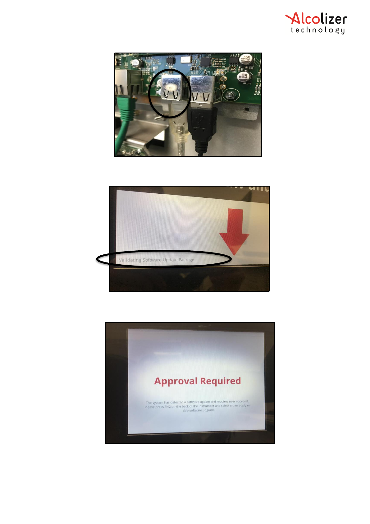
4.3.6 Via USB.................................................................................................................9
4.3.7 Validate Migration of Settings ...........................................................................13
4.4 Gas Bottle Replacement............................................................................................14
4.5 Operation Testing (Mandatory) ................................................................................15
4.6 Leak Test....................................................................................................................15
4.6.1 Procedure...........................................................................................................16
4.7 Cleaning.....................................................................................................................19
4.8 Sample System Replacement....................................................................................20
4.9 Customise Instrument...............................................................................................21
4.9.2 Camera...............................................................................................................23
4.9.3 Camera Diagnostic .............................................................................................24
4.9.4 Coin ....................................................................................................................24
4.9.5 Coin Diagnostic ..................................................................................................24
4.9.6 Wiegand.............................................................................................................24
4.9.7 Printer ................................................................................................................28
5Rentals..............................................................................................................................29
6Packing Instruction...........................................................................................................29
7QUICK GUIDE....................................................................................................................31

REF: WM4 Service WI V18.docx Page 3 © Alcolizer Technology
Uncontrolled when printed
8WM4 Unit Change ( ONLY FOR NON AUSTRALIAN STANDARDS DEVICES) .....................32
8.1 Requirements............................................................................................................32
8.2 Process ......................................................................................................................32

REF: WM4 Service WI V18.docx Page 4 © Alcolizer Technology
Uncontrolled when printed
1Competency Requirements
•Alcolizer WM4 Service Training Program
•STP C001- Visual Test Procedure Checklist
•SWP E001- Isolation Lock-Out Tag -Out
•SWP E002- Working on Live Parts
•SWP T001- Inspection of Electrical Test Instruments
•SWP T002-Inspection of Electrical Safety Instruments
•SWP T003- Inspection & Testing of Alcolizer Units
2Risks/ Safety
•Mounting assessment
oInspect and assess that the WM4 is mounted and secured safely to the wall or
mounting position.
•Environment –Exposure to heat and sun
oEnsure access to long sleeves, hat, sunscreen, and enough water.
•Insects
oCheck for insects such as wasps and spiders that can nest in the drain tube, the
straw bin and inside the case.
•Electric Shock
oVerify portable electrical equipment is “in test” (via test tag) and free of obvious
damage before use.
oRemove plug from socket outlet before working on the Alcolizer unit (other than
for testing).
•RSI (Repetitive Strain Injury)
oCable Crimping: If pain is felt in any part of your hand or arm, stop and rest. Take
regular micro-breaks, and don’t remain in one position continually performing
the same task for extended periods of time.
•Heavy Lifting: Refrain from lifting items that you are not comfortable with.
For more information, refer to Model Codes of Practice - Hazardous Manual
Tasks (ISBN9780642333070)
•Compressed Gas
oBe aware that gas cylinders contain compressed gas at high pressure.
Although the cylinders are tested and are fit for purpose, dropping, abusing
or deliberately mishandling can cause injury.
3Equipment
•FlashPro430 JTAG Programmer
•Laptop - with FlashPro430 software installed
•SD Card with latest software or USB with latest software and blank SD Card
•Portable Appliance Tester (PAT)
•Cleaning Equipment
oSpray & Wipe
oPipe cleaners
oPaper towel

REF: WM4 Service WI V18.docx Page 5 © Alcolizer Technology
Uncontrolled when printed
oWater
•Shifting Spanner for regulator assembly
•8mm nut spinner for bottle clamps
•Production Level Access Key
•USB keyboard
4Service Procedure
4.1 Visual Inspection (Mandatory)
Before starting any work on an instrument, a visual inspection must be completed to
identify any possible defects or hazards. (Risk Assessment).
4.1.1 Electrical Safety
•Supply Cable- Check for any nicks, cuts or deformations of the power cable, the plug
and the cable entry on the instrument.
•240 voltage mains shield - check the shield is in place and secure.
If any of these defects are present stop work immediately, quarantine the instrument and
return instrument to base for repair. The instrument must be repaired by a qualified
technician.
4.1.2 General Defects and Wear and Tear
Visually inspect the rest of the instrument to ensure there are no other defects present:
•No foreign objects inside the instrument case
•No damage to gas bottle and regulator assembly
•No damage to any of the tubing - high pressure line, low pressure line, purge line,
drain tube, pressure sensor.
•No loose parts - gas bottle, sub-chassis, power supply, purge pump, sample system,
straw box and lid, etc.
•No damage to instrument markings - serial number, specification panel, etc. Replace
as required.
•No damage to any of the wiring.
•No damage to LCD, PCB, purge pump, sample system.
4.2 Backup Battery
The WM4 can come with either a 9-volt alkaline battery or a rechargeable battery pack.
4.2.1 9 Volt Battery
The 9-volt backup battery must be replaced to ensure that it lasts a further 12 months. The
9V battery may need to be replaced prior to the annual service as it has 50 uses of the
machine turning on and off. Should this occur, the customer can change the battery while
the machine is ON.
•New Energizer 9v alkaline batteries come with a plastic terminal cover. Remove the
terminal cover from the new battery and cover the old battery with the plastic
terminal cover prior to disposing into the battery bin.
•Replace with the new 9volt alkaline battery.

REF: WM4 Service WI V18.docx Page 6 © Alcolizer Technology
Uncontrolled when printed
4.2.2 Rechargeable Battery Pack
The rechargeable battery pack does not need to be changed at every service as the WM will
continue to keep it charged. If the WM has frequent power losses or is frequently turned
off, the rechargeable battery pack will drain. If the wall mount has an error message on the
screen referring to the battery backup low, the following process is required:
•The backup battery needs to be disconnected from the PCBA and connected to the
battery charger. The charging process can take up to an hour.
•When fully charged, the light on the charger will remain steady and green.
•The charger can be removed and the battery pack can be plugged back into the
PCBA.
4.3 Instrument Upgrade
Use SD and FlashPro when upgrading instruments prior to AC-13.
Use USB when upgrading instruments AC-13 and above.

REF: WM4 Service WI V18.docx Page 7 © Alcolizer Technology
Uncontrolled when printed
Figure 1- Status LED
Please note: Programming Reboot cycle may take up to 10 minutes to take
effect the unit may appear frozen in this time.
4.3.1 Prior to Upgrade - All Instruments
At no point in the procedure should the backup battery be removed. The backup battery
should be replaced before starting the instrument upgrade or at the end.
4.3.2 Prior to Upgrade - Releases AC-5.0 to AC12.1
•Ensure Field Technician Authorisation key is inserted
•Navigate to the Settings page and select Shutdown Instrument (bottom right corner
using the spacebar then arrow up to upgrade and use spacebar to select)
•Select Upgrade
•Four black circles indicate settings have been exported successfully
VERY IMPORTANT: When the database exports, as the instrument shuts down it will show
four circles that will change from white to black as the process completes. If the process
does not show four filled in black circles OR at any point shows red circles, then the
database export has failed and should be restarted. If the export fails repeatedly the issue
needs to be escalated to your manager prior to any upgrade of the instrument software.
DO NOT remove the backup battery. Removing the backup battery will cause the
instrument clock to reset forcing a ten-minute wait on calibration when the clock is
synchronised.
•Wait for the STAT5 LED to be solid green. STAT1 to STAT4 should all be off.
•Remove mains power
oAll LED’s should turn off. STAT1 to STAT5 should all be off.
4.3.3 Via SD Card
During these steps some buttons on the back of the device are pressed and held over
multiple steps. It is important to not release buttons until the instructions indicate to do so.
Make sure to read and comprehend all instructions before starting the upgrade process.
The upgrade instructions refer to LEDs and
buttons on the back of the instrument as
pictured. It is important to be familiar with
the buttons and LEDs before undertaking
the instrument upgrade procedure.

REF: WM4 Service WI V18.docx Page 8 © Alcolizer Technology
Uncontrolled when printed
Figure 2- FlashPro430 Settings
Figure 3- FlashPro430 Programmer
4.3.4 Upgrade Coprocessor (ONLY IF UPGRADING BETWEEN AC-5 AND AC-12.1)
Ensure instrument is off and mains power is removed as per the previous sections.
•Before continuing ensure that:
□All SD cards are removed
□The battery remains inserted.
•Start the FlashPro430 software.
•Select the u_main.hex file for the SD Card with the latest software.
•Configuration of the software should be depicted as below.
•Remove the SOM from the main board.
•Attach the JTAG programmer.
Note
Coprocessor and SOM must be upgraded with the same firmware version.

REF: WM4 Service WI V18.docx Page 9 © Alcolizer Technology
Uncontrolled when printed
•Apply mains power.
•Confirm green device voltage light is on, on the Flash Pro Programmer.
•Press the AUTO PROG button. Programming takes 3 seconds to complete.
•Remove JTAG Programmer.
Note- If the programming step fails, try repeating this step two or three times, as it may
work on subsequent attempts.
•Remove mains power
•DO NOT remove the backup battery
•Press and hold the OFF button until all LEDs turn off. STAT1 to STAT5 should all be
off.
•Insert the SOM.
4.3.5 Upgrade SOM after the Coprocessor
•Before continuing ensure that:
othe backup battery remains inserted
oSOM is inserted
oLAN cable is disconnected
•Insert the SD card containing the firmware.
•Apply mains power.
Hold FN5 and OFF buttons together until the STAT5 LED blinks fast. Release OFF
while continuing to hold FN5. STAT4 LED will come on.
•Only release FN5 when a red line is visible at the bottom of the WM screen.
•This must be performed immediately after pressing FN5. The USB flash media with
the customer configuration on it needs to be in the instrument when the upgraded
software first boots after installation.
•When the device screen indicates the upgrade is complete, remove the SD card
containing upgrade firmware.
•Conduct a reset of the instrument. FN5 should not be pressed.
oPress and hold OFF until the STAT5 LED fast blinks (~10.0 seconds).
Release OFF stat 4 will come on.
•The device will now boot into the new firmware.
Press FN1 and confirm the firmware version reflects the current version.
•Reconnect LAN cable if it was connected prior to conducting SOM upgrade.
4.3.6 Via USB
•Turn the Authorisation off.
•Insert blank SD card and leave in the WM when firmware upgrade is finished.
•Insert the USB containing the latest firmware into a vacant USB port.
Note
Coprocessor and SOM must be upgraded with the same firmware version.

REF: WM4 Service WI V18.docx Page 10 © Alcolizer Technology
Uncontrolled when printed
•Validating Software Update Package will show in the bottom left of the screen.
•Approval Required will appear on the screen once the software has validated.
•As prompted press the FN2 button.

REF: WM4 Service WI V18.docx Page 11 © Alcolizer Technology
Uncontrolled when printed
•On the FUNCTIONS screen that will automatically open, press FN4 to select Apply
Software Update.
•The device will then show an upgrade in progress, this can take up to approximately
12 minutes to complete. This time is used to change the drain tube and gas bottle.

REF: WM4 Service WI V18.docx Page 12 © Alcolizer Technology
Uncontrolled when printed
•Device will then reboot, and the three circles will turn black.
•Update in Progress will show on the screen and a reboot will occur.
•Device will show Starting.

REF: WM4 Service WI V18.docx Page 13 © Alcolizer Technology
Uncontrolled when printed
•Once the device has restarted the below screen will show and the USB can be
removed from the port. The Firmware upgrade is now complete. To validate the
firmware version, select FN1 to open the Status screen.
4.3.7 Validate Migration of Settings
•Insert a Production Technician Authorisation Key. On the Logs, find the log record
noted prior to upgrade and check that it has the same created time as prior to
upgrade.
Note: If for any reason customer data did not migrate, it is important to resolve any specific
configuration required by the customer for the instrument.
If required to replace the main PCBA by a Plutonium PCBA, ensure that the correct settings
are entered.
Mainboard Software
Target
“20” for all PCBA versions
Coprocessor Software
Target
“2” for mainboards versions with PCBA
Sticker
00003-00
00003-01
00003-02
00003-03
00003-04
00003-05
Coprocessor Software
Target
“21” for mainboard versions with PCBA
Sticker
00003-06
00003-07
00003-08
Note: Failure to enter the correct configuration will result in a customer facing fault.

REF: WM4 Service WI V18.docx Page 14 © Alcolizer Technology
Uncontrolled when printed
Figure 5- 741001-08 PCBA Settings
4.4 Gas Bottle Replacement
•This is usually done during firmware upgrade to save time.

REF: WM4 Service WI V18.docx Page 15 © Alcolizer Technology
Uncontrolled when printed
•Turn gas cylinder off using the cylinder valve.
•Insert Field Technician ACL Key.
•Remove drain tube from back of inlet.
•Connect keyboard.
•Press and hold down the F8 button on the USB keyboard until the regulator gauge
shows zero. This will purge the regulator and gas line allowing easy removal of the
regulator.
•Unscrew left hand thread regulator from the gas bottle.
•Check the O-Ring on the regulator and replace if required.
•Unscrew the gas bottle clamps and remove the bottle.
•Place replacement gas bottle in clamps. Take up the slack in clamps and reattach the
regulator. Position the gas bottle so the regulator is pointing straight down, and
regulator dial is easily readable. Tighten gas bottle clamps.
•Attach regulator to gas bottle and turn tap on anti-clockwise one full turn.
•Press and hold down the F8 button on the USB keyboard and listen for a hissing
sound. Continue holding the button for 20 seconds. Release the Cal Gas F8 button
and press and hold it down again for a further 20 seconds (approx. 40 seconds in
total). This is important to ensure that when an automatic calibration occurs it
calibrates using the correct gas value.
•Reconnect drain tube to inlet.
•Navigate to the Calibration on screen. Tab to reset gas usage, hit space bar and
space bar on reset.
•Press the “Calibration Gas” reset button.
•Select the Calibration Gas reset button and confirm that a reset of the Calibration
Gas is required. Press the space bar and confirm reset.
•Navigate to the Calibration tab.
•Tab to concentration PPM - on tag of gas bottle. F1 to exit menu. Screen will read
“testing is disabled for self-calibration” with a timer.
•Leave Field Technician ACL key in
4.5 Operation Testing (Mandatory)
•Conduct 5 reference gas checks one minute apart. More checks are required if
adjustments have been made to the plunger.
oEnsure tolerance between reference gas and displayed readings are within
+/-5%.
•Conduct 4 zero checks. These are alternated between the positive tests.
•Ensure that the positive tests are within +/- 5% and the Zero checks MUST be Zero
(0.000)
4.6 Leak Test
This procedure shows which connection joints in the Cal gas delivery system need to be
checked for possible leaks. These checks should be carried out every time a cylinder
exchange is performed.

REF: WM4 Service WI V18.docx Page 16 © Alcolizer Technology
Uncontrolled when printed
Tools Required:
•Snoop Liquid Leak Detector- 236mL or 53 ml size
•25mL laboratory bottle with cap- half filled with
Snoop or water.
•1/8 x 200mm Clippard Tube- P/N: 30550
•PCBA and PSU liquid splash protection barrier
(L shaped rubber panel/ 500x500x160x3mm)
Alternatively, a hand towel (450x650mm) can
be used if a protection barrier is unavailable.
Electrical Safety: It is mandatory that instrument’s power is switched off while performing
the following leak check procedure.
If leak detect liquid is spilt onto electrical components, soak up spillage and allow
to dry for 24 hours before switching instrument back on again.
4.6.1 Procedure
1. Ensure cylinder valve is open (one turn counter clockwise) and that pressure gauge
indicated 1Mpa or higher. Note prior to the exchange cylinder replacement at the
start of the leak test, the pressure gauge should read above 8Mpa.
2. Install the PCBA and PSU liquid splash protection barrier over PCBA and PSU
components to protect against spillage of liquid onto electrical components.
Alternatively, a hand towel can be used if a protection barrier is unavailable.
3. Uncap snoop bottle and pull out delivery tube sufficiently (100mm-150mm) for
convenient application of liquid to connection joints.
4. Position snoop delivery tube to indicated test connection joint and squeeze bottle
sufficiently to deliver a small amount of liquid to joint surface area. Spread liquid all
around connection joint using the tip of delivery tube.
25ml Lab Bottle
236mL Size
59mL Size
L Shaped Rubber Panel
(500x500x160x3mm)
Alternative hand towel
barrier protection. Ensure
all electrical components
are covered.

REF: WM4 Service WI V18.docx Page 17 © Alcolizer Technology
Uncontrolled when printed
5. Check for appearance of any bubbles at test joints - observe for about 10 seconds.
a. No Leaks: no bubbles appear after observing for 10 seconds
b. Small Leaks: small bubbles start to appear during or after the observation period.
c. Large Leaks: larger bubbles start to appear immediately after liquid is applied.
6. If a leak is detected (any bubbles) at any of the test joints, corrective action must be
taken to fix those leaking connections.
After repair of any leaking joints, repeat leak test procedure.
7. Perform a leak test on all the indicated connection joints as marked in following
images.

REF: WM4 Service WI V18.docx Page 18 © Alcolizer Technology
Uncontrolled when printed
8. Test connection joint locations:
9. Cal solenoid internal leak test:
a. Remove the 1/8 clear tube from Cal gas flow adjust fitting.
b. Insert 1/8 x 200mm Clippard tube into Cal gas flow adjust fitting.
c. Insert end of Clippard tube into Snoop leak detect liquid inside 25mL lab bottle.
d. Check for appearance of bubbles from test tube inside leak detect liquid -
observe for about 30 seconds.
Test Location 1
If leak is detected, most likely cause
is frayed o-ring seal - replace o-ring.
Test Location 2
If leak is detected, replace
regulator assembly.
Test Location 3
If leak is detected, replace
regulator assembly.
Test Location 4
Test both connection
ports of 4mm tube fitting.
If leak is detected at blue
tube port end, remove
blue tube and trim 6mm
off end of tube using
appropriate cutting tool
and reconnect.
Test Location 5
Test both connection ports of 4mm tube
fitting. If leak is detected, retighten tube
fitting to solenoid connection port or replace
both blue tube and fitting with new parts.

REF: WM4 Service WI V18.docx Page 19 © Alcolizer Technology
Uncontrolled when printed
i. No Leak: no bubbles appear after observing for over 30 seconds.
ii. Small Leak: small Bubbles start to appear during or after the observation
period.
e. If leaking is detected, corrective action must be taken to fix the internal solenoid
leak. This most likely will require the replacement of Cal solenoid or sample
system assembly. After repair or replacement of faulty parts, repeat this leak
test procedure.
f. At completion of this test procedure, remove the 1/8 x 200mm Clippard tube for
Cal gas flow adjust fitting and re-insert the 1/8 clear tube back into fitting. Make
sure that tube is fully inserted into the flow adjust fitting. Wipe up any spillages
using a paper towel.
4.7 Cleaning
•Clean instrument internally and externally with Spray & Wipe.
1/8 Clear Tube
Cal gas flow adjust fitting
1/8 x 200mm Clippard Tube
Clippard test tube immersed in Snoop
leak detect liquid inside 25mL lab bottle

REF: WM4 Service WI V18.docx Page 20 © Alcolizer Technology
Uncontrolled when printed
•Use tube brush then a pipe cleaner with hot water to clean out sample port.
oClean out the sample port with a tube brush as described in the WM4 User
Manual.
oPush wet pipe cleaner through the straw inlet hole using a back-and-forth
motion.
oFollow-up with several dry pipe cleaners with the same back-and-forth
motion.
oIn some instances, it may be required to remove the sample system for
easier access.
•Replace drain tube.
THE FOLLOWING SECTIONS ARE ONLY TO BE USED IF REQUIRED OR REQUESTED
4.8 Sample System Replacement
This section is only required if a sample system replacement is required.
•Turn instrument off
•Remove cable and pressure sensor tube from PCB
•Remove two fastening nuts and take old sample system out
•Apply the short to the old sample system and return to service
•Remove the short applied to the new sample system
•Put new sample system in and secure with two nuts
•Reconnect cables and pressure sensor tube to PCB
•Power machine back on
•Navigate to the Factory Settings page. Tab across to resets and press the “Fuel Cell”
reset button.
Notes:
1. Calibration gain limits for WM4 are embedded in the operation software.
2. WM4 has three calibration Error Fault messages:
A. Calibration error (38) Fuel cell gain over range. The calculated fuel
cell gain is over the maximum allowed value.
Fix: Is the calibration gas bottle empty? Is the gas bottle valve
closed? Faulty fuel cell, replace.
B. Calibration error (39) Fuel cell gain under range. The calculated fuel
cell gain is under the minimum allowed value.
Fix: Check fuel cell for corrosion or physical damage.
C. Calibration error (50) (44) Fuel Cell Gain Drift. (50) The fuel cell gain
calculated from the most recent calibration has drifted too far from
the current fuel cell gain. When the WM4 sees a large change in gain
value from one calibration to the next, it thinks that there is an issue.
Fix: The fuel cell is faulty or there is a problem with the calibration
gas.
If possible, purge gas lines before calibration. Calibrate (a number of
times if purging is not possible). Replace sample system if needed.
3. Make sure that you have reset sample system after replacement.
Other manuals for WM4
1
Table of contents
Other Alcolizer Test Equipment manuals

Alcolizer
Alcolizer LE 5 User manual

Alcolizer
Alcolizer Druglizer LE5 User manual

Alcolizer
Alcolizer Druglizer LE5 User manual

Alcolizer
Alcolizer Druglizer LE5 User manual

Alcolizer
Alcolizer Druglizer LE5 User manual

Alcolizer
Alcolizer Easy Check User manual

Alcolizer
Alcolizer HH4 User manual

Alcolizer
Alcolizer Centurion Quantum User manual

Alcolizer
Alcolizer Druglizer LE5 User manual

Alcolizer
Alcolizer Centurion User manual