Alfalaval GJ 8 User manual

Instruction Manual
Alfa Laval GJ 8
Covering:
Standard Machines
First published: 2015-08
ESE032025-EN1 2015-08
Original manual


Table of Contents
The information herein is correct at the time of issue but may be subject to change without prior notice
1. EC Declaration of Conformity ...... ..... ..... ...... ..... ...... ..... ...... ..... ...... ..... ..... ......................................…… 1
2. Safety .. ..... ...... ..... ...... ..... ...... ...... ..... ..... ...... ..... ...... ..... ...... ..... ...... ..... ..... ...................................... …… 2
2.1. Important information . ..... ...... ...... ..... ..... ...... ..... ...... ..... ...... ..... ...... ..... ..... ...................................... …… 2
2.2. Warning signs ... ...... ..... ...... ...... ..... ..... ...... ..................................... ..... ..... ................................ …. 2
2.3. Safety precautions .... ..... ...... ...... ..... ..... ...... ..... ...... ..... ...... ..... ...... ..... ..... ...................................... …… 3
3. Introduction ..... ..... ...... ...... ..... ..... ...... ..... ...... ..... ...... ..... ...... ..... ..... ...................................... …… 4
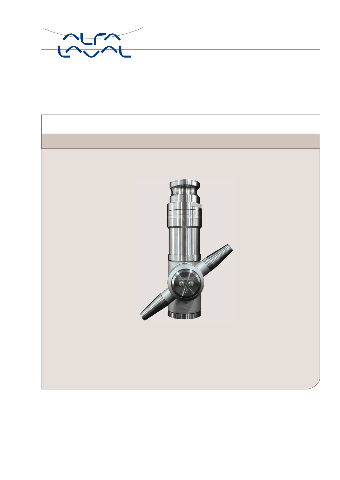
3.1. Description . ...... ..... ...... ..... ..... ...... ..... ...... ..... ...... ..... ...... ..... ..... ...................................... …… 4
3.2. Intended Use . ...... ..... ...... ..... ..... ...... ..... ...... ..... ...... ..... ...... ..... ..... ...................................... …… 4
3.3. Patents and trademarks . ...... ..... ...... ..... ..... ...... ..... ...... ..... ...... ..... ...... ..... ..... ...................................... …… 4
3.4. Marking . ...... ..... ...... ..... ..... ...... ..... ...... ..... ...... ..... ...... ..... ..... ...................................... …… 4
4. Installation . ...... ..... ...... ..... ...... ...... ..... ..... ...... ..... ...... ..... ...... ..... ...... ..... ..... ...................................... …… 5
4.1. Unpacking/delivery ... ..... ...... .......... ..... ...... ..... ...... ..... ...... ..... ...... ..... ..... ...................................... …… 5
4.2. Installation .. ..... ...... .......... ...... ..... ...... ..... ...... ..... ...... ..... ..... ...................................... …… 6
4.3. Recycling Information ..... ...... ..... ..... ...... ..... ........... ...... ........... ..... ..... ...................................... …… …...…. 8
5. Operation . . ...... ..... ...... ..... ..... ...... ..... ........... ...... ..... ..... ...................................... …………..... 9
5.1. Operation/Control ..... ..... ...... ...... ..... ..... ............ ..... ...... ..... ...... ..... ..... ...................................... …………….. 9
5.2. Trouble Shooting ..... ............ ..... ...... ..... ...... ..... ..... ….. ….. …. ...................................... …………….. 10
5.3. Cleaning Solution Leakage ..... ..... ..... ............ ..... ...... ..... ...... ..... ..... ...................................... …………….. 12
5.4. Poor Cleaning Performance.... ..... ..... ............ ..... ...... ..... ...... ..... ..... ...................................... …………….. 13
5.5. Recommended Cleaning . . ...... ..... ..... ............ ..... ...... ..... ...... ..... ..... ...................................... …………….. 14
6. Maintenance . ...... ..... ...... ..... ............ ..... ...... ..... ...... ..... ..... ...................................... …………….. 15
6.1. General Maintenance.... ..... ...... ..... ..... ..... ............ ..... ...... ..... ...... ..... ..... ...................................... …………….. 15
6.2. General dismantling set up ..... ..... ..... ............ ..... ...... ..... ...... ..... ..... ...................................... …………….. 16
6.3. General dismantling . . ..... ...... ..... ............ ..... ...... ..... ...... ..... ..... ...................................... …………….. 17
6.4. Inspection and Service of Components . ...... .......... ...... ..... ..... ...................................... …………….. 18
6.5. Reassembly ..... ...... ..... ..... ............ ..... ...... ..... ...... ..... ..... ...................................... …………….. 21
7. Technical Data .. ..... ...... ..... ..... ............ ..... ...... ..... ...... ..... ..... ...................................... …………….. 23
7.1. Technical Data .. ...... ..... ..... ............ ..... ...... ..... ...... ..... ..... ...................................... …………….. 23
7.2. Performance Data .... ..... ...... ..... ..... ............ ..... ...... ..... ...... ..... ..... ...................................... …………….. 24
7.3. Dimensions . .......... ..... ............ ..... ...... ..... ...... ..... ..... ...................................... …………….. 25
7.4. Trax Simulation Tool .. ..... ...... ..... ............ ..... ...... ..... ...... ..... ..... ...................................... …………….. 26
8. Parts List and Service Kits ... ...... ..... ..... ............ ..... ...... ..... ...... ..... ..... ...................................... …………….. 27
8.1. GJ8 View ..... ..... ...... ..... ............ ..... ...... ..... ...... ..... ..... ...................................... …………….. 27
8.2. Assembly Drawings - 1 & 2 ..... ..... ..... ............ ..... ...... ..... ...... ..... ..... ...................................... …………….. 28
8.3. Assembly Drawings - 3, 4, 5, 6, 7 & 8. ..... ..... ............ .......... ...... ..... ..... ...................................... …………….. 29
8.4. Assembly Drawings - 9, 10, 11, 12, 13, 14, 15, 16 & 17............. ...... ..... ..... ...................................... …………….. 31
8.5. Assembly Drawings –18, 19, 20, 21, 22, 23, 24 & 25..... ..... ...... ..... ..... ...................................... …………….. 33
8.6. Assembly Drawings –26, 27, 28 & 29 ..... ............................. ...................................... …………….. 35
8.7. Assembly Drawings –30, 31, 32, 33 & 34... ............ ..... ...... ..... ...... ..... ..... ...................................... …………….. 37
8.8. Parts List .... ..... ...... ..... ...... ..... ..... ............ ..... ...... ..... ...... ..... ..... ...................................... …………….. 40
8.9. Minor Service Kit ...... ..... ...... ..... ..... ..... ............ ..... ...... ..... ...... ..... ..... ...................................... …………….. 43
8.10. Major Service Kit ...... ..... ...... ................. ..... ...... ..... ...... ..... ..... ...................................... …………….. 45
9. Appendix A ………............................................................................................................................................. …… 47

1
EC Declaration of Conformity
The designated company
Alfa Laval Tank Equipment Inc.
Company name
604 Jeffers Circle –Exton, PA –19341, United States
Address
+1 610 408 9940
Phone no.
hereby declare that
Tank Cleaning Machine
Alfa Laval GJ 8
Denomination
Type
From serial numbers from E-0001 to E-XXXX
is in conformity with the following regulations and directives with amendments:
- The Machinery Directive 2006/42/EC
DS/EN ISO 12100:2011
- The Pressure Directive 97/23/EC
According to its own volume and the rated pressure range the product is regarded an Article 3, paragraph 3 Equipment
The person authorised to compile the technical file is the signer of this document.
Executive VP Operations
Andrew Delaney
Title
Name
Signature
2015-05-18
Exton, United States
Date
Place

2. Safety
2
Unsafe practices and other important information are emphasized in this manual. Warnings are emphasized by means of
special signs.
Always read the manual before using the tank cleaning machine!
2.1 Important information
WARNING
Indicates that special procedures must be followed to avoid serious personal injury.
CAUTION
Indicates that special procedures must be followed to avoid damage to the tank cleaning machine.
NOTE
Indicates important information to simplify or clarify procedures.
2.2 Warning signs
General warning:
Dangerous electrical voltage:
Caustic agents:

2. Safety
3
All warnings in the manual are summarized on this page.
Pay special attention to the instructions below so that severe personal injury and/or damage to the tank cleaning machine
are avoided.
2.3 Safety precautions
Installation:
Always read the technical data thoroughly. (See chapter 7 Technical Data)
Any tank-cleaning machine can develop a static electricity charge while in operation.
If the tank being cleaned contains a combustible liquid or vapor having a risk of ignition or explosion, it is imperative to
have the Alfa Laval Gamajet properly grounded using the provided location on the unit.
Operation:
Always read the technical data thoroughly. (See chapter 7 Technical Data)
Necessary precautions must be taken if leakage occurs as this can lead to hazardous situations.
Always handle lye and acid with great care.
When an Alfa Laval Gamajet is operating, there should be covers over every tank opening.
These covers should be sealed well enough to withstand the full force of the jet striking the cover plate.
If the cleaning solution were hot, corrosive, or toxic, a leak would present a serious hazard to any personnel
in the immediate vicinity or to any exposed electrical equipment.
Warning: Any tank-cleaning machine can develop a static electricity charge while in operation. If the tank being
cleaned contains a combustible liquid or vapor having a risk of ignition or explosion, it is imperative to have the
Alfa Laval Gamajet properly grounded using the provided location on the unit.
Maintenance:
Always read the technical data thoroughly. (See chapter 7 Technical Data).
Never service the tank cleaning machine when it is hot.
Always use Alfa Laval genuine spare parts.
Transportation of the tank cleaning machine:
Always drain the tank cleaning machine head and accessories of any liquid
Always use original packaging or similar during transportation.

3. Introduction
4
3.1
D
escript
i
on
The Alfa Laval GJ 8 is a fluid-driven (turbine-driven) 360° rotary nozzle machine designed for cleaning the interior surfaces of
a variety of medium to large tanks and vessels. It is powered entirely by the cleaning solution; it requires no electricity,
compressed air or lubricant for operation. The Alfa Laval GJ 8 is designed primarily for portable service; however, the unit
may also be permanently installed in a vessel. If the Alfa Laval GJ 8 is permanently mounted inside a tank, we strongly
recommend inspecting the unit every few hundred hours of operation. (See Chapter 6 - Preventative Maintenance for more
information.)
WARNING: Under no conditions, whatsoever, should the Alfa Laval GJ 8 ever be immersed in anything, unless you
have prior approval from Alfa Laval Tank Equipment, Inc. Failure to comply with this restriction will void the
warranty!
In order to handle the broadest possible range of applications, the stainless steel Alfa Laval GJ 8 is available with dual or triple
nozzles, and an extensive selection of nozzle sizes, stators (non-rotating turbine), and O-ring materials. The nozzles are
available in six interchangeable sizes - 1/4", 9/32", 5/16", 3/8" and 7/16" /(6.3 mm, 7.1mm, 8mm, 9.5mm and 11.1 mm). The
Alfa Laval Gamajet wash cycle time can be adjusted for special applications by changing the stator, and nozzle size.
Interchangeable stators and nozzle sizes are available for either low or high pressures and/or flow rates. A complete
description of the technical specifications and materials of construction of the Alfa Laval GJ 8 is contained in section 8 Parts list
and Service kits.
3.2 Intended Use
It is to be verified by the end-user:
- that the tank cleaning machine is in conformity with respect to tank, vessel or container size in which it will be used.
- that the construction materials (both metallic and non-metallic) are compatible with product, flushing media, cleaning media,
temperatures and pressure under the intended use.
3.3 Patents and trademarks
This Instruction Manual is published by Alfa Laval Tank Equipment without any warranty. Improvements and changes to this
Instruction Manual may at any time be made by Alfa Laval Tank Equipment without prior notice. Such changes will, however,
be incorporated in new editions of this Instruction Manual.
© Alfa Laval Tank Equipment. All rights reserved.
The Alfa Laval logotype is a trademark or a registered trademark of Alfa Laval Corporate AB. "Gamajet" is a trademark or
registered trademark of Alfa Laval Tank Equipment. The Alfa Laval GJ 8 product has patent in the US (US 6.123.271 & US
6.561.199). Other products or company names mentioned herein may be the trademarks of their respective owners. Any rights
not expressly granted herein are reserved.
3.4 Marking
Alfa Laval tank cleaning machines are all marked to allow recognition of machine type, machine name, Serial number and
manufacturing address. The marking is placed on the body of the tank cleaning machine.
Alfa Laval Tank Equipment –Exton, PA
Patent #: 6,123,271 & 6,561,199

4. Installation
5
Read the instructions carefully and pay special attention to the warnings! Always check the tank cleaning machine before
operation.
4.1
U
npacking/
deliv
er
y
Step 1
CAUTION
Alfa Laval cannot be held responsible for incorrect unpacking.
Check the delivery for:
1. Complete Cleaning Machine
2. Delivery note
Step 2
Remove any packing material
Step 3
Inspect the tank cleaning machine for visible transport damage. Inspection!

4. Installation
6
Read the instructions carefully and pay special attention to the warnings! Always check the tank cleaning machine before
operation.
4.2 Installation
Step 1
Always read the technical data thoroughly.
(See chapter 7 Technical Data)
Step 2
Assembly
Every Alfa Laval Gamajet is operationally tested before shipment and is ready to run after unpacking. No assembly is
required prior to use. The Alfa Laval Gamajet has been configured to meet the operating conditions (at the Alfa Laval Tank
Equipment Inc., not at the pump) given to us, e.g. pressure, flow, temperature, cycle time, etc.
Note: Any change to the originally supplied operating conditions will affect the performance of the Alfa Laval Gamajet
accordingly.
Step 3
Inlet Connections
The Alfa Laval GJ 8 is supplied with a combination 1-½” NPT female/2" quick disconnect male inlet connection or 1-½” BSP /2"
quick disconnect male inlet connection. It is recommended that when using the NPT/BSP connection the mating male thread be
wrapped with PTFE pipe joint tape prior to mounting. This will minimize any chance of leakage and will make subsequent
removal much easier.
Step 4
Mounting
Before mounting the Alfa Laval GJ 8, make sure the supply line has been adequately flushed. It should be mounted on a rigid
1-½” pipe using an adjustable or pipe wrench. In most applications, the Alfa Laval GJ 8 will be mounted in the upright position
(inlet connection pointing up); however, the Alfa Laval Gamajet will function at any orientation. We do not recommend attaching
the machine to a hose while in the inverted or horizontal orientation. This form of mounting is not rigid and, thus, will not
maintain the Alfa Laval Gamajet’s position should the unit become unbalanced due to clogging of the nozzles. In addition, we
do not recommend using a Triple Nozzle or directional version machine with a flexible supply line. The dynamic imbalance of
the Triple Nozzle will affect the Alfa Laval Gamajet’s performance accordingly.
Warning: When attaching the Alfa Laval GJ 8 onto the supply pipe, ALWAYS use the wrench on the Collar at the
top/inlet of the unit. Never use a wrench on Stem or Tee Housing to tighten the unit onto the pipe. Doing so risks
internally damaging the machine.

4. Installation
7
Read the instructions carefully and pay special attention to the warnings! Always check the tank cleaning machine before
operation.
Step 5
Location inside Tank
Generally, a single Alfa Laval Gamajet should be positioned in the approximate center of the vessel in order to equalize the
cleaning radius in all directions. Some vessels may have specific cleaning problems such as coils or heavy deposits such as
the liquid level line (bathtub ring). In these situations the Alfa Laval Gamajet should be located closer to the difficult area for the
best cleaning results.
Tanks with internal mechanisms or structures such as an agitator shaft, impellers or baffles will require careful positioning to
minimize the “shadow effect” on areas which do not receive direct jet impact. Sometimes, more than one machine, or, more
than one placement of a single machine, may be necessary to completely avoid shadow problems.
Step 6
Entry Openings
When using the Alfa Laval GJ 8, the vessels being cleaned must provide entry openings large enough to avoid interference
during insertion and removal. The minimum opening size required for Alfa Laval GJ 8 is 228.6 mm / 9.0 inches in diameter.
Step 7
Vessel Drainage
If it is necessary to clean the floor of a vessel, remember that standing liquid will diminish the effectiveness of the jet by
covering any soils underneath. Wherever possible, the tank floor should be pitched toward the drain and the drainage opening
should be large enough to eliminate or reduce any liquid buildup or puddling. If gravity alone is insufficient, a scavenger or
stripper pump should be connected to the drain to suck out the excess wash fluid. In extreme cases, it may be necessary to
use smaller nozzles on the Alfa Laval Gamajet, or even to operate it intermittently to allow time for draining.
Step 8
Filters and Strainers
All tank cleaning systems should be equipped with a filter or strainer that will trap solids 15 mm/1/16" (175 micron, 80 mesh) or
larger, as these will not pass through the Alfa Laval Gamajet. These large particles will not harm the machine, but they can
become caught in one of the internal passages of the machine and cause it to stop turning or reduce its cleaning effectiveness
due to a loss of flow. It will then be necessary to disassemble the Alfa Laval Gamajet and remove the blockage.
In recirculating (closed-loop) cleaning or any other application where the cleaning solution may carry abrasive solids in
suspension, adequate filtration is a must. These particles can be extremely destructive to the Alfa Laval Gamajet, pumps,
valves, and other system components. Filters, properly installed and maintained, will more than pay for themselves with lower
overall operating costs in these applications. Furthermore, to ensure that clogged filters or strainers are cleaned, we
recommend using automatic self-cleaning models.

4. Installation
8
Read the instructions carefully and pay special attention to the warnings! Always check the tank cleaning machine before
operation.
Step 9
Capacity Of Supply Pump
The Alfa Laval GJ 8 can be used with either a centrifugal or positive displacement (constant volume), PD, style pump. In
most cases, if the machine is to be used with a centrifugal pump, it should be configured so that the pump will operate close
to its best efficiency point. The end user must, therefore, take all of the plumbing, elevation, and 8 pressure/flow rate
requirements into account.
If a PD style pump (i.e. piston pump, plunger pump, or mechanical diaphragm pump, etc.) will supply the wash fluid to the
Alfa Laval GJ 8 a different set of rules apply. PD pumps are fixed volume pumps whose flow rate is dependent upon the
speed of the pump; the pumps also have a pressure rating which is the maximum operating pressure. Note: Do not
confuse the maximum operating pressure of a PD pump with the actual operating pressure. The actual operating
pressure is dictated by the fixed flow rate of the pump, the Alfa Laval GJ 8 and the plumbing system. If a PD pump is
used, the Alfa Laval GJ 8 should be sized to, first, match the flow capability of the pump and, second, not exceed the pump's
maximum operating pressure (taking the pressure rating of the plumbing system into account, also).
WARNING: For high-pressure applications (over 250 psig/17 bar), the pressure of the system must "ramp up" to its
operating pressure. If the system experiences a pressure spike or pressure increases at a rate of more than 250
psig per second, the machine may be damaged and parts will wear out prematurely. Damage resulting from this
phenomenon is not covered by the warranty.
4.3 Recycling Information
• Unpacking
-Packing material consists of wood, plastics, cardboard boxes and in some cases metal straps.
-Wood and cardboard boxes can be reused, recycled or used for energy recovery.
-Plastics should be recycled or burnt at a licensed waste incineration plant.
-Metal straps should be sent for material recycling.
• Maintenance
-All metal parts should be sent for material recycling.
• Scrapping
- At end of use, the equipment must be recycled according to relevant, local regulations. Beside the equipment itself, any
hazardous residues from the process liquid must be considered and dealt with in a proper manner. When in doubt, or in the
absence of local regulations, please contact your local Alfa Laval sales company.

5. Operation
9
Read the instruction carefully and pay special attention to the warnings!
5.1 Operation/Control
Step 1
Always read the technical data thoroughly. See chapter 7 Technical Data
CAUTION
Alfa Laval cannot be held responsible for incorrect operation/control.
Step 2
Never touch the tank cleaning machine or the pipelines when pumping hot liquids.
Step 3
Initial Startup
Every Alfa Laval GJ 8 that ships is accompanied by a Birth Certificate. This document indicates how the Alfa Laval GJ 8
performed in our testing tank before it shipped based on the operating conditions supplied to Alfa Laval Tank Equipment Inc.
To ensure the longest possible life of the Alfa Laval GJ 8, please verify the operating conditions and, most importantly, the
machine’s cycle time. The cycle time can be measured by, first, picking a fixed point inside of a vessel as a reference and,
second, timing how long it takes the same nozzle to pass back over that point in the vessel. (This, naturally, will not be the
exact same spot because the spray pattern is indexing.) The measured time in seconds directly corresponds to the machines
full cycle time in minutes. In other words, a single 10-second rotation translates to a 10 minute full cycle time.

5. Operation
10
Pay attention to possible faults
Read the instructions carefully
5.2 Trouble Shooting
Yes
No
Does Rotor (pos.
10) turn freely by
hand?
-Cracked Input Pinion (pos. 39) - Section 6.4 Inspection and Service of Components
- Damaged planetary gearhead (pos. 13) - Section 6.4 Inspection and Service of
Components
- Loose Stem Cap Washer (pos. 42) - Section 6.4 Inspection and Service of
Components
- Bent stem Collar (pos. 2) - Section 6.4 Inspection and Service of Components
No
Yes
-Cracked/Loose Input Pinions (pos. 39) - Section 6.4 Inspection and Service of
Components
- Worn gear bushing (pos. 32) - Section 6.4 Inspection and Service of
Components
- Worn Tee/ Nozzle housing bearing and cup (pos. 29, 31) - Section 6.4
Inspection and Service of Components
- Loose nozzle housing cup (pos. 30) - Section 6.4 Inspection and Service of
Components
Do Nozzle (pos.
5) and Tee
Housing (pos.
4) both index
when Rotor
(pos. 10) is
turned?
Yes
No
Does only Tee
Housing
(pos. 4) index?
- Worn Tee/ Nozzle housing bevel gear (pos. 17, 18) - Section 6.4 Inspection and
Service of Components
- Using Clutch Drive Machine, if nozzle housing does not operate during normal
operation- Section 6.4 Inspection and Service of Components
- Cracked/Loose input pinion (pos. 39) - Section 6.4 Inspection and Service of
Components
- Very loose gear set screw (pos. 40) - Section 6.4 Inspection and Service of
Components

5. Operation
11
Pay attention to possible faults
Read the instructions carefully
Step 1
INSUFFICIENT FLOW
The Alfa Laval Gamajet was configured to meet certain operating conditions supplied to us, such as flow rate (m3/Hr/ GPM),
pressure (Bar/ PSI), temperature, chemical content of the wash fluid, cycle time, etc. If the Nozzle size is too small and/or the
opening at the bottom of the Stator is too large, the Tee Housing will not turn.
Look for restrictions in the fluid supply such as a clogged filter, kinked hose, or deposits in the piping.
Step 2
TIGHT CLEARANCES
A newly overhauled Alfa Laval GJ 8 may fail to operate when first returned to service. If the machine seems otherwise fine, try
running it with at least one Nozzle Tip removed. The reduction in pressure and additional flow will invariably be enough to
overcome the extra resistance of new Bearings and Seals. A few minutes of operation should loosen the clearances enough for
the machine to run normally with the Nozzles remounted.
Step 3
DEBRIS INSIDE
Loosen the Collar Set Screw (45) and remove the Collar (8), then lift out the Stator (9). Look for and remove any debris caught
in the passageways of Stator and Rotor (10). Remove any material wound around the Rotor Shaft (21). In addition check for
any debris caught in the outlet holes of the Stem (3), the vent holes of the (26), the nose of the Tee Housing (4), the Nozzle
Housing (5), and the Nozzles (7).

5. Operation
12
Pay attention to possible faults
Read the instructions carefully
5.3 Cleaning Solution Leakage
-Worn Bearings & Seals
Water exiting from the CIP holes in the Tee Housing will cause a slight spray to exit around the Tee and Nozzle Housing.
However, excessive leakage from the Tee Housing or Nozzle Housing usually indicates worn Housing Bearings (29), and Seals
(31). Inspect them for wear (sealing lips are worn to a smooth surface) or damaged lips or loss of spring tension (indicated by
excessive dry deposits of dirty or abrasive cleaning solution on the spring), and replace as required.
-Worn Bearing Cups
Inspect the Bearing Cups (30) for excessive wear (grooved or scored), particularly near the inside flange where they contact the
(31) Seals. Replace any that show distinct grooves.
-Worn Static Seal Contact Surfaces
Inspect the Bearing and Seal contact surfaces of the Stem (3) and the nose of the Tee Housing (4). If these are worn or
grooved, new Bearings and Seals will be ineffective. Replace the damaged parts as required.
-Leak On Either Side of Bearing Housing
Verify that the Stem Cap SHCS (41) are tight. If tight, inspect the Stem Collar (2), Rotor Shaft Upper Bearing Housing (26), and
Stem (3) for nicks or burrs. File, if necessary.
-Worn Stem Collar O-Rings
Severe leakage between the Inlet Collar (1) and Stem Collar (2) may indicate worn or damaged Stem Collar O-rings (56) and
(57). Remove the Stem Collar as described in Section 2, and inspect the O-rings for signs of damage or wear.

5. Operation
13
Pay attention to possible faults
Read the instructions carefully
5.4 Poor Cleaning Performance
-Inadequate Flow and Pressure
Check the pressure at the Alfa Laval Gamajet inlet under actual operating conditions. The supply piping and hoses must be
large enough to handle the flow rate required for the nozzle size being used to ensure adequate pressure.
Insufficient pressure may also result from line losses when the machine is far from the pump, so the line size must be increased
accordingly for long runs. Although the Alfa Laval Gamajet will rotate at low flow rates, effective cleaning may require
considerably more flow. Proper mechanical operation (the unit turns) is NOT the same thing as effective cleaning (the soils
have been removed)!
-Chemical Concentration and Temperature
Verify that the cleaning solution is the correct compound and in the concentration needed for the deposit being cleaned. If
heating is necessary, also check that the solution is at the proper temperature.
-Plugged Nozzles
Unscrew the Nozzles (7) and inspect for any debris.
-Slow or no Rotation of the Housings
This will result in partial or erratic washing coverage. Refer to previous sections for more information.
-Alfa Laval Gamajet Configuration
Determine if the deposit being cleaned requires greater jet impact or longer jet dwell time (slower rotation) for more thorough
scrubbing. Confirm that the Alfa Laval Gamajet nozzle size, turbine, and gearing are correct for the specific application. Contact
Alfa Laval Tank Equipment for assistance, if needed.
-Inadequate Drainage
Ensure that the vessel drains the effluent or used wash fluid as fast as it’s being sprayed in through the Alfa Laval Gamajet.
The floor of the vessel should be sloped or pitched toward the drain and the drainage opening should be large enough to
gravity-drain the effluent from the vessel. If you still have puddling (build-up of the wash fluid so it covers the floor and shields
the residues underneath), use some form of pump to suck out the effluent.

5. Operation
14
The Tank Cleaning machine is designed for cleaning in place (CIP). CIP = Cleaning In Place. Study the instructions carefully
and pay special attention to the warnings! NaOH = Caustic Soda, HNO3 = Nitric acid.
5.5 Recommended Cleaning
Step 1
Always handle lye and acid with great care.
Caustic danger!
always use rubber gloves! Always use protective goggles!
Step 2
Never touch the pump or the pipelines when sterilizing.
Danger of burns!
Step 3
Always rinse well with clean water after using a cleaning agent.
NOTE
Cleaning agents must be stored/disposed of in accordance with
current regulations/directives.
Always rinse!
Clean Water Cleaning agent

6. Maintenance
15
Maintain the Tank Cleaning Machine with care. Read the instructions carefully and pay special attention to the warnings!
Always keep Minor spare parts kit in stock.
6.1 General Maintenance
Step 1
Always read the technical data thoroughly. (see chapter 7 technical Data)
Step 2
Recommended spare parts:
Order service kits from the service kits list
(See 8.9 Minor Service Kit & 8.10 Major Service Kit)
Ordering spare parts:
Contact your local Alfa Laval Sales Company.

6. Maintenance
16
Maintain the Tank Cleaning Machine with care. Read the instructions carefully and pay special attention to the warnings!
Always keep Minor spare parts kit in stock.
6.2 General dismantling set up
Step 1
NOTE
A rigorously implemented preventative maintenance program will significantly reduce repair costs over the life of the Alfa Laval
Gamajet. The foundation of such a program is regularly scheduled inspections to discover and replace worn or damaged parts
before they can cause the failure of other, more costly, components. The inspection intervals required will depend on the
severity of the application, but a complete internal inspection at 100 hours of operation is recommended initially.
Step 2
STORAGE
The Alfa Laval Gamajet should be washed out with clean water after each use to remove any foreign material or soft
substances left in the machine that may harden during storage and cause the Alfa Laval Gamajet to seize or lock up. A clean
water rinse through the Alfa Laval Gamajet will also wash out any residues of chemical cleaners or recirculated wash water that
could adversely affect the seals and O-rings during prolonged contact in storage. The best position to store the Alfa Laval
Gamajet is to stand it up with the inlet connection facing down.
Step 3
EXTERNAL INSPECTION INTERVALS
Before every shift, the Stator (9) and the Nozzles (7) should be inspected for debris. Examine the Stator by loosening the Collar
Set Screw (45) and removing the main section of the machine from the Collar (8). Note: One does not have to remove the Inlet
Collar (8) from the supply pipe when performing this check; simply, loosen the set screw (45) and unthread the body from the
(8). Look into each Nozzle for signs of debris or build-up. Also, the vent holes on either side of the (26) should be checked for
blockage. Use a fine wire or compressed air to clear them, if necessary.
Step 4
INTERNAL INSPECTION INTERVALS
An interval of 100 hours is recommended initially. If all of the components are found to be in acceptable condition after the first
100 hours, the Alfa Laval Gamajet may then be inspected and routine preventive maintenance should be performed every 300
to 500 hours of operation, depending on the severity of use.
Step 5
TIPS
All the Bearings, Bushings, Seals and O-rings are wear parts. Ideally, they should all be replaced, as a group, every 300 to 500
hours of operation, depending on the severity of use. If just one Bearing or Seal is worn or damaged, replace both it and its
mate, not just the worn or damaged part.

6. Maintenance
17
Read the instructions carefully. The items refer to the parts list and service kits section.
6.3 General dismantling
Step 1
Inlet Collar
Loosen the Collar Set Screw (45) with the 1/8" Hex Key.
Unthread the Collar (8) and remove the Stator (9).
Tip: If (8) does not unthread easily, remove (45) and spray a generous amount of liquid lubricant into the threaded hole. Turn
(8) back and forth to slowly unthread. Forcing the (8) off of the unit without the use of a lubricant may gall the threads on the (8)
and/or (2).
Step 2
Base Assembly
Remove the Socket Head Cap Screws (SHCS) (43) with a 1/4” Hex Key, the Lockwashers (44), and Base (14) from the Tee
Housing (4).
Remove the Nut (52) with an 11/32” socket and Lockwasher (51) from the Output Shaft (12).
Using slotted screwdriver, remove the Idlers Shafts (15), Idler Gear Assemblies (16), and the Output Pinion (11).
Step 3
Stem Collar
Unscrew the SHCS (42) with 5/32” Hex Key, and remove them along with the Lockwashers (41).
Pull the Stem Collar (2) from the Rotor Shaft Upper Bearing Housing (26).
Step 4
Gear Train Assembly
Remove the Gear Train Assembly from the body by tapping on the Ouput Shaft (12) at the Base end of the machine with the
handle of a screw driver.
Step 5
Nozzle Housing
Remove the Nameplate Screws (46) and Lockwashers (47) with a 5/16" socket.
Pull the Nozzle Housing (5) off the nose of the Tee Housing (4).
Remove the inner Housing Seal (31) and Bearing (29). Tip: Use a screwdriver on both sides of the flange of (29) to aid in
removal.
Step 6
Tee Housing
Using a 1/8” slotted screwdriver, remove the Ring Gear Retaining Ring (20), and Pullout the Ring Gear (19).
Unscrew the SHCS (41) using a 5/32" Hex Key, and remove the Lockwashers (42) and Idler Shaft Base (28).
Tip: if the (28) is difficult to remove, screw the SHCS (43) (removed in Step 2.2.2) back into (28) and use them for leverage. Or,
using two slotted screwdrivers, pry between the Tee Housing (4) and Stem (3).
Pull the (4) from the (3).
Remove the lower Tee Housing (31).
Pry/Pull the lower Tee Housing Bearing (29) and Tee Housing Bevel Gear (17) from (3).
Table of contents
Other Alfalaval Ultrasonic Jewelry Cleaner manuals