manuals.online logo
Brands
  1. Home
  2. •
  3. Brands
  4. •
  5. alfatronix
  6. •
  7. Power Supply
  8. •
  9. alfatronix A/C.PVPro-S Manual

alfatronix A/C.PVPro-S Manual

◼FEATURES
• 12V & 24V systems compatible (9-32Vdc)
• 5Vdc output voltage
• Apple and Android auto-detect
• Supplied with FASTON crimp connectors
◼TECHNICAL DATA
◼RING REMOVAL
1. Insert screwdriver in slot under USB Charger.
2. Twist screwdriver to remove ring.
CARACTÉRISTIQUES
• Compatible avec les systèmes 12V & 24V (9-32Vdc)
• Tension de sortie 5Vcc
• Auto-détection Apple et Android
• Fourni avec des bornes plates encliquetables FASTON
◼CARACTÉRISTIQUES TECHNIQUES
◼RETRAIT DE L’ANNEAU
1. Insérer un tournevis dans l’encoche sous le
Chargeur USB.
2. Tourner le tournevis pour retirer l’anneau.
INFORMATION
OPERATING & ASSEMBLY
INSTRUCTIONS
USB Power Supply
T E L: +44 (0) 1202 715 517 • [email protected]m
◼ASSEMBLY (PVPro / PVPWp/ PV65R)
1. Isolate the circuit before you connect or disconnect the device.
2. Choose a suitable mounting surface ensuring nothing behind can be
damaged, then drill a Ø30mm hole.
3. Choose installation method, either; Standard Ring (A) or Front fitting (B).
4. Connect input positive to the terminal indicated +, connect the input nega-
tive to the terminal indicated –.
A/C. PVPro-S/-D; PVPWp-S/-D; PV65R-S/-D
1. Press ‘Standard Ring’ over front of USB Charger, ensuring the slot is at the
bottom.
2. Insert body through the hole.
3. Tighten the nut onto back of body ensuring front is aligned.
B/D. PVPro-SFf/-DFf; PVPWp-SFf/-DFf; PV65R-SFf/-DFf
1. Place bezel over the USB Charger.
2. Mark screw hole positions.
3. Install through Ø30mm hole and screw into position.
4. Press ‘Bezel Ring’ over front of the USB Charger, ensuring the slot is at the
bottom.
◼ASSEMBLY
E. PV-USB2
1. Isolate the circuit before you connect or disconnect the device.
2. Connect input positive to the terminal indicated +, connect the input nega-
tive to the terminal indicated –.
3. Insert USB plug into USB socket (this will be stiffer than a standard USB
socket to help keep plug in place).
4. Secure all wires with cable-ties.
5. Secure unit with either cable-ties or double sided sticky pads (supplied).
29 Newtown Business Park, Poole, BH12 3LL, UK • www.alfatronix.com
This device complies with the EU directive 2014/30/EU.
The type plate is located on the top of the device.
SAFETY
ENGLISH
Part
Number Power Input
Voltage
Output
Voltage Dimensions WeightOutputs IP
Rating
PVPro-S 2.1A 9-32Vdc 5Vdc Ø37x33mm 25g1 IP30
PVPro-D 3.0A 9-32Vdc 5Vdc Ø37x33mm 28g2 IP30
PVPWp-S 1 2.1A 9-32Vdc 5Vdc Ø37x33mm 28g IP65
PVPWp-D 2 3.0A 9-32Vdc 5Vdc Ø37x33mm 31g IP65
PV65R-S 1 2.1A 9-32Vdc 5Vdc Ø37x49mm 40g IP65
PV65R-D 2 3.0A 9-32Vdc 5Vdc Ø37x49mm 43g IP65
PV-USB2 2.1A 9-32Vdc 5Vdc 113x24x15mm 17g1 IP30
ASSEMBLY
ENGLISH • FRANÇAIS • DEUTSCH • ESPAÑOL
vO
◼SAFETY
• The device must not be exposed to severe mechanical shocks.
• The device must not be exposed to extreme temperature, direct sunlight or
vigorous vibration.
• The device may only be used within a dry environment, such as a vehicle.
• Do not install this device in the proximity of hot vehicle parts.
• The wiring harness should be protected by fuses.
• Observe the magnitude and polarity of the input voltage when installing,
incorrect polarity of the input could damage the circuit.
• Isolate the circuit before you connect or remove the device.
• Never open the device casing and never repair it. The device must be re-
placed if it is damaged.
◼PACKING CONTENTS
A/C. PVPro-S/-D; PVPWp-S/-D; PV65R-S/-D
• 1 x USB Charger, 2 x Crimp Connectors, 1x Standard Ring, 1x Nut , 1x
Washer
B/D. PVPro-SFf/-DFf; PVPWp-SFf/-DFf; PV65R-SFf/-DFf
• 1 x USB Charger, 2 x Crimp Connectors, 1 x Bezel Back, 1x Bezel Ring, 3x
Screws
E. PV-USB2
• 1 x PV-USB2, 4 x Cable-ties, 2 x Crimp Connectors, 2 x Sticky pads
CONTENTS
PVPro-S / PVPro-D / PV65R-S / PV65R-D
PVPro-SFf / PVPro-DFf / PV65R-SFf / PV65R-DFf INFORMATIONS
◼ASSEMBLAGE (PVPro / PVPWp / PV65R)
1. Isoler le circuit avant la connection ou déconnexion de l’appareil.
2. Choisissez une surface de montage adequate en vous assurant que rien ne
risque d’être endommagé derrière, ensuite percer un trou de Ø30mm.
3. Choisissez la méthode d’installation, soit; anneau standard (A) ou façade
(B).
4. Brancher l’entrée positive sur la borne indiquée +, brancher l’entrée
negative sur la borne indiquée –.
A/C. PVPro-S/-D; PVPWp-S/-D; PV65R-S/-D
1. Presser l’anneau de façade sur le devant du Chargeur USB, en vous
assurant que l’encoche est en bas.
2. Insérer le corps du convertisseur dans le trou.
3. Serrer l’écrou à l’arrière du corps du convertisseur en vous assurant que
l’avant est bien carré.
B/D. PVPro-SFf/-DFf; PVPWp-SFf/-DFf; PV65R-SFf/-DFf
1. Placer la façade sur le Chargeur USB.
2. Marquer les positions des trous de vis.
3. Installer dans le trou de Ø30mm et visser en position.
4. Presser l’anneau de façade sur le devant du Chargeur USB, en vous
assurant que l’encoche est en bas.
◼ASSEMBLAGE
E. PV-USB2
1. Isoler le circuit avant la connection ou déconnexion de l’appareil.
2. Brancher l’entrée positive sur la borne indiquée +, brancher l’entrée
negative sur la borne indiquée –.
3. Insérer le connecteur USB dans la prise USB (Cela sera plus rigide qu’une
prise standard USB, afin de garantir un meilleur maintien du connecteur en
place).
4. Fixer tous les cables avec des attaches autobloquantes.
5. Fixer le produit avec les attaches autobloquantes ou les autocollants double
-face fournis.
L’appareil est conforme aux exigences de la Directive UE 2014/30/EU.
La plaquette d’identification se trouve sur le haut de l’appareil.
SÉCURITÉ
FRANÇAIS
ASSEMBLAGE
◼SÉCURITÉ
• Tenir l’appareil éloigné de tout choc mécanique.
• Ne pas exposer l’appareil à des températures extrêmes, au soleil direct ou à
d’importantes vibrations.
• L’appareil ne doit être utilisé que dans un environnement sec, comme un véhicule.
• Ne pas installer l’appareil dans un véhicule à haute temperature.
• La sangle de connexion doit être protégée par des fusibles.
• Veillez à la puissance électrique et la polarité de la tension de sortie lors de l’installa-
tion. Une polarité incorrecte de sortie pourrait entraîner des dommages du circuit.
• Isoler le circuit avant de connecter ou de démonter l’appareil.
• Ne jamais ouvrir l’appareil ou tenter de le réparer. L’appareil doit être remplacé en
cas de dommage.
◼CONTENU
A/C. PVPro-S/-D; PVPWp-S/-D; PV65R-S/-D
• 1 x Chargeur USB, 2 x Bornes Plates Encliquetables, 1 x Anneau standard, 1
x Ecrou, 1 x Rondelle
B/D. PVPro-SFf/-DFf; PVPWp-SFf/-DFf; PV65R-SFf/-DFf
• 1 x Chargeur USB, 1 x Façade arrière, 1 x Anneau de façade, 3 x Vis
E. PV-USB2
• 1 x PV-USB2, 4 x Serre-câble, 2 x Bornes Plates Encliquetables,
2 x Autocollants
CONTENU
Référence Sorties Charge Entrée
Tension
Sortie
Tension Dimensions Poids Protections
IP
PVPro-S 1 2.1A 9-32Vdc 5Vdc Ø37x33mm 25g IP30
PVPro-D 2 3.0A 9-32Vdc 5Vdc Ø37x33mm 28g IP30
PVPWp-S 1 2.1A 9-32Vdc 5Vdc Ø37x33mm 28g IP65
PVPWp-D 2 3.0A 9-32Vdc 5Vdc Ø37x33mm 31g IP65
PV65R-S 1 2.1A 9-32Vdc 5Vdc Ø37x49mm 40g IP65
PV65R-D 2 3.0A 9-32Vdc 5Vdc Ø37x49mm 43g IP65
PV-USB2 1 2.1A 9-32Vdc 5Vdc 113x24x15mm 17g IP30
E.3
E.4 E.5
PV-USB2
E.1,2
+
-
E
B/D.2,3
B/D.4
B/D.1
B/D
A/C.3 A/C.4
+
-
A/C.1 A/C.2
A/C
PVPro-S / PVPro-D / PV65R-S / PV65R-D
◼FUSING
Each PVPro/PVPWp/PV65R/USB2
must be fused individually:
12/24V input voltage = 2A fuse
◼FUSIBLE
Chaque PVPro/PVPWp/PV65R/USB2 doit être individuel-
lement protégé par un fusible: Tension d’entrée 12/24V =
Fusible de 2A
1,2 3 A
B D
C
◼CARACTERÍSTICAS
• Compatible con sistemas de 12V y 24V
• Tensión de salida de 5 V CC
• Autodetección de Apple y Android
• Suministrado con terminales FASTON
◼DATOS TÉCNICOS
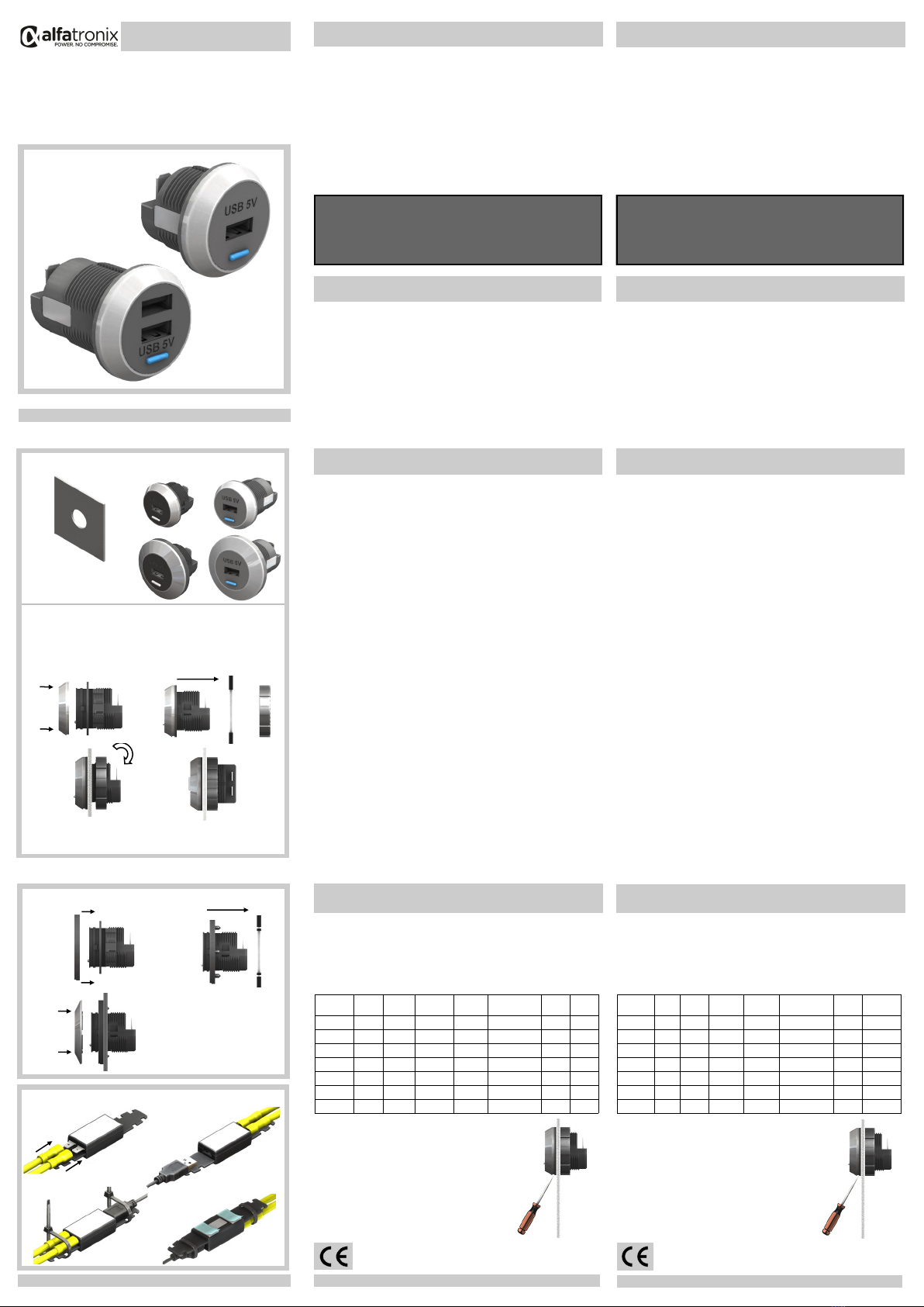
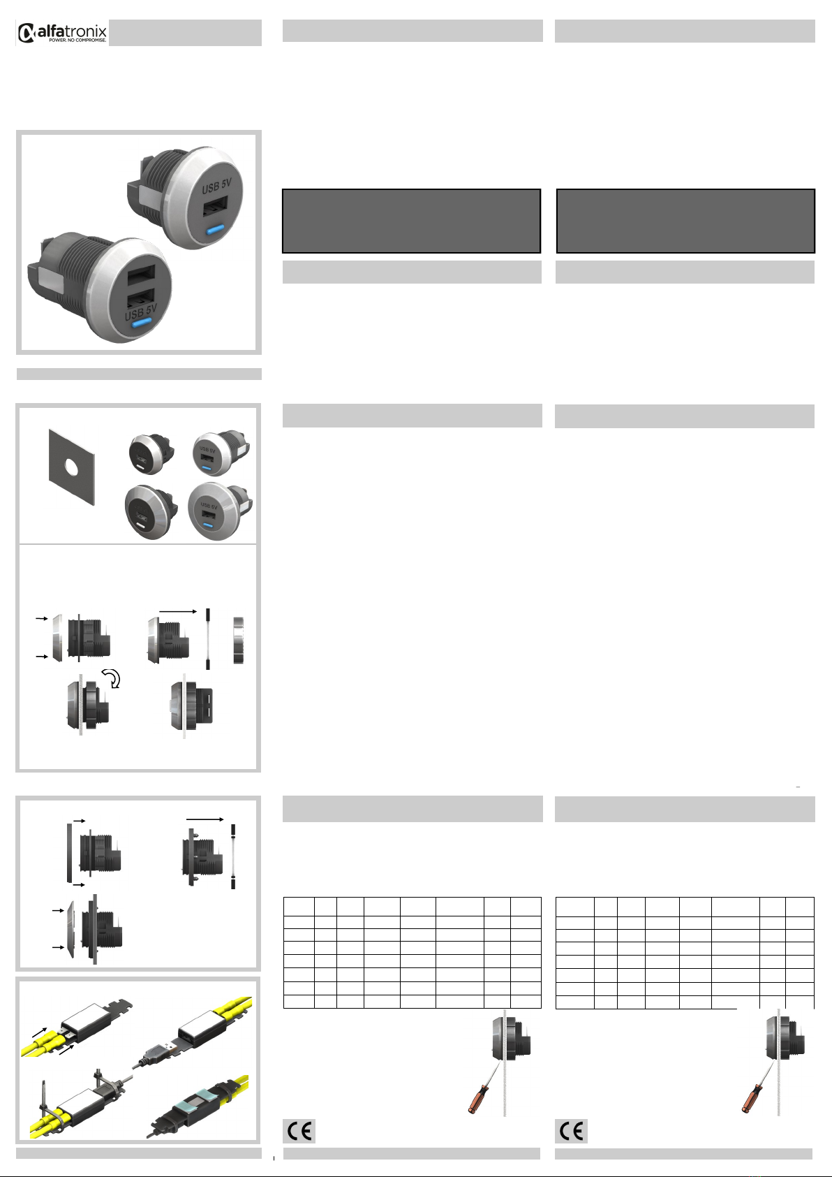
◼EXTRACCIÓN DEL ANILLO
1. Introduzca el destornillador en la abertura bajo el
Cargador USB .
2. Gire el destornillador para extraer el anillo.
◼EIGENSCHAFTEN
• 12V & 24V systemgerecht (9-32Vdc)
• 5Vdc Ausgangsspannung
• Apple und Android Auto-Erkennung
• FASTON Flachsteckverbindungen
◼TECHNISCHE DATEN
◼ENTFERNUNG DES RINGS
1. Schraubenzieher in den Schlitz an der Unterseite
des USB Ladegeräts einführen.
2. Schraubenzieher drehen um den Ring zu ent-
fernen.
INFORMATIONEN
OPERATING & ASSEMBLY
INSTRUCTIONS
USB Power Supply
T E L: +44 (0) 1202 715 517 • [email protected]m
◼MONTAGE (PVPro / PVPWp / PV65R)
1. Trennen Sie den Stromkreis bevor Sie das Gerät anschließen oder wieder ent-
fernen.
2. Wählen Sie eine geeignete Montagefläche und stellen Sie sicher dass nichts
dahinter beschädigt werden kann bevor Sie ein Ø30mm Loch bohren.
3. Wählen Sie eine Installationsmethode, entweder; Standartring (A) oder Frontblende
(B).
4. Verbinden Sie den positiven Eingang mit der Klemme die mit + gekennzeichnet ist ,
Verbinden Sie den negativen Eingang mit der Klemme die mit –gekennzeichnet ist.
A/C. PVPro-S/-D; / PVPWp-S/-D; PV65R-S/-D
1. Drücken Sie den Standartring über den PVPro stellen Sie sicher das der Schlitz
unten ist .
2. Setzen Sie diesen in das Loch.
3. Verschrauben Sie die Mutter auf der Rückseite des Gehäuses und stellen Sie sicher
dass die Vorderseite rechtwinklig ist.
B/D. PVPro-SFf/-DFf; PVPWp-SFf/-DFf; PV65R-SFf/-DFf
1. Frontblende über dem USB Ladegerät platzieren.
2. Schraublöcher markieren.
3. Durch das Ø30mm Loch installieren und festschrauben.
4. Frontblendenring auf der Vorderseite des USB Ladegeräts festdrücken, bitte
sicherstellen das der Schlitz unten ist.
◼MONTAGE
E. PV-USB2
1. Trennen Sie den Stromkreis bevor Sie das Gerät anschließen oder wieder ent-
fernen.
2. Verbinden Sie den positiven Eingang mit der Klemme die mit + gekennzeichnet ist ,
Verbinden Sie den negativen Eingang mit der Klemme die mit –gekennzeichnet ist.
3. Stecken Sie den USB Stecker in die USB Buchse ( diese wird schwergängiger als
Standard USB Buchsen sein um den Stecker in Position zu halten).
4. Sichern Sie alle Kabel mit Kabelbindern.
5. Sichern Sie das Gerät entweder mit Kabelbindern oder Doppelklebepads
(mitgeliefert).
29 Newtown Business Park, Poole, BH12 3LL, UK • www.alfatronix.com
Dieses Gerät ist in Erfüllung der EU Direktive 2014/30/EU. Das
Typenschild befindet sich auf der Oberseite des Gerätes.
SICHERHEIT
DEUTSCH
Artikel Leistung Eingangs–
spannung
Ausgangs–
spannung Größe Gewicht
Aus-
gänge Schutzart
PVPro-S 2.1A 9-32Vdc 5Vdc Ø37x33mm 25g1 IP30
PVPro-D 3.0A 9-32Vdc 5Vdc Ø37x33mm 28g2 IP30
PVPWp-S 1 2.1A 9-32Vdc 5Vdc Ø37x33mm 28g IP65
PVPWp-D 2 3.0A 9-32Vdc 5Vdc Ø37x33mm 31g IP65
PV65R-S 2.1A 9-32Vdc 5Vdc Ø37x49mm 40g1 IP65
PV65R-D 2 3.0A 9-32Vdc 5Vdc Ø37x49mm 43g IP65
PV-USB2 1 2.1A 9-32Vdc 5Vdc 113x24x15mm 17g IP30
MONTAGE
◼SICHERHEIT
• Das Gerät darf nicht extremen mechanischen Schocks, extremen Tempera-
turen, direkter Sonneneinstrahlung oder starken Vibrationen ausgesetzt
werden und soll nur in einer trockenen Umgebung installiert werden wie zum
Beispiel ein Fahrzeug.
• Das Gerät nicht auf heißen Fahrzeugteilen installieren.
• Den Kabelbaum durch Sicherungen schützen.
• Die Stärke und Polarität des Ausgangs sollte bei der Installation beobachtet
werden. Inkorrekte Polarität am Ausgang könnte den Schaltkreis beschädigen.
• Den Schaltkreis isolieren bevor das Gerät ein–oder abmontiert wird.
• Sollte das Gerät defekt sein muss es ausgetauscht werden. Das Öffnen des
Gehäuses oder die Reparatur des defekten Gerätes ist untersagt.
◼INHALT
A/C. PVPro-S/-D; PVPWp-S/-D; PV65R-S/-D
• 1 x USB Ladegerät, 2 x Flachsteckverbindungen, 1 x Standartring, 1 x Mutter,
1 x Unterlegscheibe
B/D. PVPro-SFf/-DFf; PVPWp-SFf/-DFf; PV65R-SFf/-DFf
• 1 x USB Ladegerät, 2 x Flachsteckverbindungen, 1 x Frontblendenpack, 1 x
Frontblendenring, 3 x Schrauben
E. PV-USB2
• 1 x PV-USB2, 4 x Kabelbinder, 2 x Flachsteckverbindungen, 2 x Klebepads
INHALT
INFORMACIÓN
◼ENSAMBLAJE (PVPro / PVPWp / PV65R)
1. Aislar el circuito antes de conectar o desconectar el dispositivo.
2. Escoger una superficie de montaje adecuada y asegurar que no pueda
dañarse nada detrás, después hacer un orificio de Ø30mm.
3. Escoja el método de instalación: anillo estándar (A), o aro (B).
4. Conectar la entrada positiva al terminal +, y la negativa al terminal –.
A/C. PVPro-S/-D; PVPWp-S/-D; PV65R-S/-D
1. Presione el anillo estándar en la parte delantera del PVPro, asegurando
que la abertura quede en la parte inferior.
2. Quitar la tuerca del cuerpo del convertidor e introducir la estructura por el
orificio.
3. Apretar la tuerca en la parte de atrás de la estructura asegurando que la
parte delantera queda en ángulo recto.
B/D. PVPro-SFf/-DFf; PVPWp-SFf/-DFf; PV65R-SFf/-DFf
1. Sitúe el aro sobre el PVPro.
2. Marque las posiciones de los orificios para los tornillos.
3. Instale en el orificio de 30 mm de diámetro y atorníllelo hasta que quede
fijado.
4. Presione el anillo de bisel sobre la parte delantera del Cargador USB ,
asegurando que la abertura quede en la parte inferior.
◼ENSAMBLAJE
E. PV-USB2
1. Aislar el circuito antes de conectar o desconectar el dispositivo.
2. Conectar la entrada positiva al terminal +, y la negativa al terminal –.
3. Introducir el conector USB en el receptor USB (será más duro que un
receptor USB normal para que no se mueva).
4. Asegurar todos los cables y amarres.
5. Asegurar la unidad con los amarres o con las pegatinas dobles
(suministradas).
Este aparato cumple los requisites prescritos en la directive de la UE
2014/30/EU. La placa de identificación se encuentra en la parte superior
del aparato.
SEGURIDAD
ESPAÑOL
ENSAMBLAJE
◼SEGURIDAD
• El aparato no debe quedar expuesto a fuertes sacudidas mecánicas.
• El aparato no debe quedar expuesto a temperaturas extremas ni a una
radiación directa del sol ni a intensas vibraciones.
• El aparato sólo se puede poner en funcionamiento en un entorno seco, es
decir, en el interior del vehículo.
• No lo instale en partes calientes del vehículo.
• Proteger las conexiones con fusibles.
• Durante el montaje preste atención a la altura y la polaridad de la tensión de
salida. Una polaridad incorrecta o sobretensión pueden perjudicar el circuito
de corriente.
• Cortar la corriente antes de conectar el aparato o de desmontarlo.
• No está permitido abrir ni reparar el aparato. En caso de avería, deberá
cambiarse.
◼VOLUMEN DE SUMINISTRO
A/C. PVPro-S/-D; PVPWp-S/-D; PV65R-S/-D
• 1 x Cargador USB , 2 x Terminales de Crimpar, 1 x Anillo estándar, 1 x
Tuerca, 1 x Arandela
B/D. PVPro-SFf/-DFf; PVPWp-SFf/-DFf; PV65R-SFf/-DFf
• 1 x Cargador USB , 2 x Terminales de Crimpar, 1 x Aro trasero, 1 x Anillo
de bisel, 3 x Tornillos
E. PV-USB2
• 1 x PV-USB2, 4 x Brida, 2 x Terminales de Crimpar, 2 x Pegatinas
VOLUMEN DE SUMINISTRO
Número de
pieza Potencia Entrada
Voltaje
Salida
Voltaje Dimensiones PesoSalidas IP
PVPro-S 2.1A 9-32Vdc 5Vdc Ø37x33mm 25g1 IP30
PVPro-D 3.0A 9-32Vdc 5Vdc Ø37x33mm 28g2 IP30
PVPWp-S 1 2.1A 9-32Vdc 5Vdc Ø37x33mm 28g IP65
PVPWp-D 2 3.0A 9-32Vdc 5Vdc Ø37x33mm 31g IP65
PV65R-S 2.1A 9-32Vdc 5Vdc Ø37x49mm 40g1 IP65
PV65R-D 2 3.0A 9-32Vdc 5Vdc Ø37x49mm 43g IP65
PV-USB2 1 2.1A 9-32Vdc 5Vdc 113x24x15mm 17g IP30
PVPro-S & PVPro-D
A
C
PVPro-S / PVPro-D / PV65R-S / PV65R-D
PV-USB2
◼SICHERUNGEN
Jeder PVPro/PVPWp/PV65R/USB2 muss einzeln
abgesichert werden:
12/24V Eingangsspannung = 2A Sicherung
◼FUSIBLE
Cada PVPro/PVPWp/PV65R/USB2 debe ser fusionado
individualmente:
12/24V Entrada Voltaje = 2A fusible
E.3
E.4 E.5
PV-USB2
E.1,2
+
-
E
PVPro-SFf / PVPro-DFf / PV65R-SFf / PV65R-DFf
B/D.2,3
B/D.4
B/D.1
B/D
A/C.3 A/C.4
+
-
A/C.1 A/C.2
A/C
PVPro-S / PVPro-D / PV65R-S / PV65R-D
1,2 3 A
B D
C

This manual suits for next models

12

Other alfatronix Power Supply manuals

alfatronix PV USB-1 Manual

alfatronix

alfatronix PV USB-1 Manual

alfatronix AD Series Manual

alfatronix

alfatronix AD Series Manual

alfatronix PowerTector PT40 Manual

alfatronix

alfatronix PowerTector PT40 Manual

alfatronix PowerTector PT10 Manual

alfatronix

alfatronix PowerTector PT10 Manual

alfatronix PV-USB1 Manual

alfatronix

alfatronix PV-USB1 Manual

alfatronix PR65R Manual

alfatronix

alfatronix PR65R Manual

alfatronix PVPro-S/A Manual

alfatronix

alfatronix PVPro-S/A Manual

Popular Power Supply manuals by other brands

Comelit EN54C Series user manual

Comelit

Comelit EN54C Series user manual

Moxa Technologies DR-120 Series Hardware installation guide

Moxa Technologies

Moxa Technologies DR-120 Series Hardware installation guide

American Magnetics 430 Installation, operation and maintenance instructions

American Magnetics

American Magnetics 430 Installation, operation and maintenance instructions

Akyga AK-ND-67 user manual

Akyga

Akyga AK-ND-67 user manual

Pulsar BLACK POWER PSBEN 5012D/LCD manual

Pulsar

Pulsar BLACK POWER PSBEN 5012D/LCD manual

LinMot S02-72/1000 installation guide

LinMot

LinMot S02-72/1000 installation guide

Juniper SRX 3400 installation instructions

Juniper

Juniper SRX 3400 installation instructions

Wintop iPlugDim quick start guide

Wintop

Wintop iPlugDim quick start guide

Fluke i50s user manual

Fluke

Fluke i50s user manual

Lütze CPS2B1-480-24 instruction manual

Lütze

Lütze CPS2B1-480-24 instruction manual

instagrid ONE max user manual

instagrid

instagrid ONE max user manual

Edwards Signaling S-25-24 installation instructions

Edwards Signaling

Edwards Signaling S-25-24 installation instructions

WFCO WF-8700 Series Operator's manual

WFCO

WFCO WF-8700 Series Operator's manual

Diamond Systems Jupiter-MM-5000 user manual

Diamond Systems

Diamond Systems Jupiter-MM-5000 user manual

Bosch FPP-RNAC-8A-4C Operation and installation guide

Bosch

Bosch FPP-RNAC-8A-4C Operation and installation guide

Thermaltake Toughpower XT TPX-575M user manual

Thermaltake

Thermaltake Toughpower XT TPX-575M user manual

CCS PDS-30 Instruction guide

CCS

CCS PDS-30 Instruction guide

B+K precision 9140 Series user manual

B+K precision

B+K precision 9140 Series user manual

manuals.online logo
manuals.online logoBrands
  • About & Mission
  • Contact us
  • Privacy Policy
  • Terms and Conditions

Copyright 2025 Manuals.Online. All Rights Reserved.