ALFRA TMH 50 User manual


11
Always...
• activate the hand-operated liftingmagnet
completely
• activate the lifting magnet on metallic,
ferromagnetic materials
• use the entire magnetic surface for lifting
• lift on level surfaces
• check the magnetic holding force by shaking
when picking up the load
• clean the magnetic surface and keep it clear
of dirt, chips and welding sputter
• set the lifting magnet down gently to prevent
damage to the magnetic surface
• check the hazard area when pivoting the load
• respect the stated maximum load before pivoting
• inspect the magnetic surface and the entire
lifting magnet for damage
• follow the instructions in this operating manual
• instruct new operators to the safe use of
lifting magnets
• respect local, country-specific guidelines
• store in a dry place
!
Dear customer,
Thank you for purchasing an ALFRA product. Please read these operation instructions closely before using
your device for the first time and keep them along with the enclosed Product Control Card for later reference.
SAFETY INSTRUCTIONS
Dangers can occur when transporting loads by lifting devices due to improper handling and/or poor
maintenance, which may cause serious accidents with fatal physical injuries. Please read these operation
instructions closely and observe all safety instructions mentioned therein. Contact the manufacturer if you
have any questions.
Never...
• lift round or arched objects
• exceed the stated maximum load
• lift loads over people
• lift more than one work piece at a time
• switch the lifting magnet o before setting
down the load safely
• allow the load to sway or bring to a sharp
and immediate stop
• lift loads exceeding the recommended
dimensions
• lift loads with cavities, cut-out openings
or drilled holes
• modify the lifting magnet or remove
operating labels
• use the lifting magnet if damaged or missing parts
• strain the underside of the magnet through
heavy impact or blows
• position yourself beneath the lifted load
• leave the loadhanging unattended
• use the lifting magnet without having been
properly instructed
• use if you have not read and understood these
operating instructions completely
• use the lifting magnet to support, lift or
transport persons
• operate the lifting magnet in temperatures
higher than 60°C (140°F)
• expose to corrosive substances
!
People with cardiac pacemakers or other medical appliances may only use the
lifting magnet following approval by their physician.
EN

12
PROPER USE
The TMH 50 is a hand-operated permanent lifting magnet designed to lift ferromagnetic, metallic loads.
It may only be used according to its technical data and determination. Proper use includes adherence to the
start-up, operating, environment and maintenance conditions specified by the manufacturer. The user bears
sole responsibility for understanding the operating manual as well as for proper use and maintenance of
the lifting magnet.
DEVICE DESCRIPTION
The TMH50 (Thin Material Handlifter) is a switchable lifting magnet with manual actuation designed to lift
and transport ferromagnetic materials. To activate the magnet, push the activation lever (A) into the ON
position until it audibly latches into place. The installed permanent magnet (B) generates a magnetic field
in the lower magnetic plate area (D). Owing to the special design of the TMH 50, this magnetic field is very
compact and develops excellent adhesive force especially on thin materials of less than 10 mm.
The activation lever must be lifted slightly at its end and returned by 60° into the OFF position in order to
deactivate the magnet.Care must be taken that the lever springs back when working on thin materials.
A stable carrying handle (C) made of aluminium can be found on the upper side of the hand-operated lifting
magnet. The load-bearing capacity of the lifting magnet is equivalent to at least 1/3 of the maximum pull-o
strength of the magnet.
A) Activation lever
B) TMC 300 Magnetic base
(41100)
C) Carrying handle
D)Magnetic surface
Be sure to read the operation instructions completely before using the magnet for the first time!
!

13
MARKINGS ON THE HANDOPERATED LIFTING MAGNET
Detailed descriptions for handling and operating conditions of the TMH 50 can be found on the upper side
of the lifting magnet. This labeling must not be modified, damaged or removed. Otherwise the manufacturer
cannot be held responsible for any personal injuries, property damage or accidents resulting from this fact.
New labels must be ordered from the manufacturer if necessary.
Prod.-No.189414231
TECHNICAL DATA
Prod.-No.: 41100.H
Designation TMH 50 Hand-operated lifting magnet
Pull-o strength >300 kg from 6 mm S235 >660 lbs from 0.25"
Max. load-bearing capacity:
(on flat material
with safety factor >1:3) 50 kg from 3 mm S235 110 lbs from 0.12"
Max. load-bearing capacity:
(at 90° inclination of the load
with safety factor >1:3) 35 kg from 3 mm S235 75 lbs from 0.12"
Dead weight of the unit 1,6 kg 3,6 lbs
Storage temperature -30°C to +60°C -22°F to +140°F
Operating temperature -30°C to +60°C -22°F to +140°F

14
STARTUP
You receive a completely assembled lifting magnet and a detailed operating manual. Please check the
condition of the goods upon receipt for any damage incurred during transport, and make sure the delivery
is complete. If you have any problems, please contact the manufacturer immediately.
1. Follow the safety instructions. Clean the workpiece and the lower magnetic plate of the lifting magnet.
2. Position the lifting magnet at the centre of gravity of the load. The lifting magnet is pre-tensioned slightly
in order toavoid inadvertent slipping and droppingof the magnet (e.g. when used in a vertical or other
forced position).
3. Align the lifting magnet according to the desired application.
4. Turn the activation lever by 60° into the ON position until it audibly latches into place (with a slight tilting).
5. Lift the load slightly and check its secure hold by shaking.
6. Now move your load slowly and smoothly. Avoid swinging or jarring.
7. After the load has been set down completely and safely, you can deactivate the lifting magnet.
To do this, push the activation leverat its far end upwards (1.) and moveit into the OFF position (2.).
The maximum dimensions of the loads to be lifted depend to a large extent on the geometry and flexural
stiness of the work pieces. This is due to the fact that, in case of bending, an air gap (view page 15) forms
under the magnetic surface resulting in a significant decrease of the load-bearing capacity. During each lift,
watch for any deformation of the work piece that might occur. If necessary, check for any air gap developing
at the edges of the TiN-coated magnetic surface (e.g. with a sheet of paper; 80g/m2).
Immediately stop the lifting operation if there is any excessive deformation or an air gap.
!
Never exceed the dimensions and/or the load-bearing capacity of the
material thickness given intable 2.
!

15
BASIC INFORMATION CONCERNING THE HANDLING OF MAGNETIC
LIFTING GEAR IN PARTICULAR TML / TMH
The magnetic surface is located on the underside of the lifting magnet incorporating dierent magnetic poles
which generate the magnetic holding force through magnetic flux when activated. The maximum holding
force that can be achieved depends on dierent factors which are explained below:
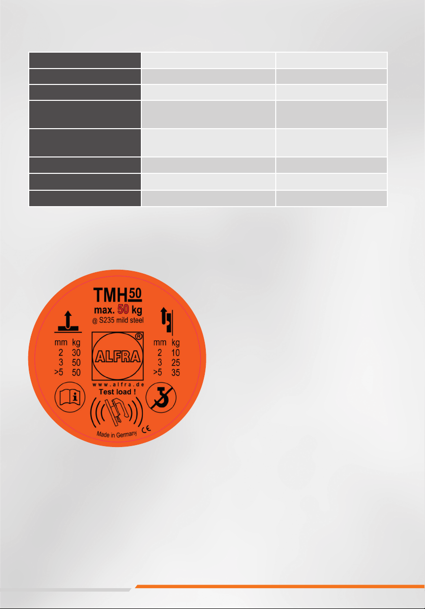
Material thickness
The magnetic flux of the lifting magnet requires a minimum material thickness to flow completely into the
load. Below this minimum thickness of material, the maximum holding force is reduced subject to material
thickness. Conventional switchable permanent magnets have a deeply penetrating magnetic field similar to
tree tap roots, and require a large material thickness to achieve maximum holding force. The compact magnetic
field of TML and TMH magnets is similar to a shallow root and achieves maximum holding force even when
used on thin materials (see performance data in table 2).
Material
Every material reacts in a dierent way to penetration of the magnetic field lines. The load-bearing capacity
of the lifting magnets is determined using an S235 material. Steels with high carbon content or whose
structure has been changed by heat treatment have a low holding force. Foamed or porous cast components
also have a lower holding force, so that the given load-bearing capacity of the lifting magnet can be
downgraded on the basis of the following table 1.
Table 1
Surfacequality
The maximum holding force of a lifting magnet can be achieved in case of a closed magnetic circuit in which
the magnetic field lines can connect up freely between the poles, thus creating a high magnetic flux. In contrast
to iron, for example, air has very high resistance to magnetic flux. If an air gap is formed between the lifting
magnet and the work piece, the holding force will be reduced. In the same way, paint, rust, scale, surface
coatings, grease or similar substances all constitute a space(i.e. an air gap), between work piece and lifting
magnet. Furthermore, an increasein surface roughness or unevenness has an adverse eect on the magnetic
holding force. Reference values for your TMH 50 can be found in table 2.
Load dimensions
When working with large workpieces such as girders or plates, the load canpartly become deformed during
the lift. A large steel plate would bend downwards at the outer edges and create a curved surface which no
longer has full contact with the bottom of the magnet. The resulting air gap reduces the maximum load-
bearing capacity of the lifting magnet. In contrast to this, nor should objects be hollow or smaller than the
magnetic surface, as otherwise the entire power of the lifting magnet will not be used.
Load alignment
During load transport care must be taken that the lifting magnet is always at the centre of gravity of the work piece
and that load, or lifting magnet respectively, is always aligned horizontally. In this case, the magnetic force of
the lifter acts with its full pull-o strength at right anglesin relation to the surface and the maximum rated load-
bearing capacity is achieved through the 1:3 standard safety factor. If the position of work piece and lifting magnet
changes from horizontal to vertical, the lifting magnet is operated in shear mode and the workpiece can slip
away to the side. In shear mode, the load-bearing capacity decreases dependent upon the coecient of friction
between the two materials.
Temperature
The high-power permanent magnets installed in the lifting magnet irreversibly lose their magnetic properties
from a temperature of more than 80°C, so that the full load-bearing capacity is never reached again even after
the magnet has cooled down. Please note the specifications on your product and in the operating manual.
Material Magneticforce in %
Non-alloyed steel (0.1-0.3% C content) 100
Non-alloyed steel (0.3-0.5% C content) 90-95
Cast steel 90
Grey castiron 45
Nickel 11
Stainlesssteel, aluminium, brass 0

16
MAINTENANCE AND INSPECTION OF THE HANDOPERATED LIFTING MAGNET
The user is obliged to maintain and service the hand-operated lifting magnet TMH 50 in compliance with
the specifications in the operating manual and according to the country-specific standards and regulations
(e.g. ASME B30.20B, DGUV-Information 209-013; AMVO).
Before every use...
• visually inspect the hand-operated lifting magnet for damage
• clean the surface of the workpiece and the underside of the magnet
• free the underside of the magnet of rust, chips or unevenness
Weekly...
• inspectthe lifting magnet and activation lever for deformation, cracks or other defects
• make sure the activation lever is working properly and latches correctly into place
• inspect the bottom of the magnet for scratches, pressure points or cracks. Have the magnet repaired
by the manufacturer if necessary
Monthly...
• check the markings and labelling on the lifting magnet for legibility and damage and replace them
if necessary
Annually...
• have the load-bearing capacity of the lifting magnet checked by the supplier or an authorised workshop
Unauthorised repairs or modification to the lifting magnet are not permitted.
If you have any questions, contact the manufacturer.
!

17
DETAILED PERFORMANCE DATA FOR THE HANDOPERATED LIFTING
MAGNET TMH
Values shown for load capacity of the TMH 50 are based on material S235 JR for the maximum, vertical
tractive force with 0° deviation from the load axis and additionally under a 90° inclined load. The safety
factor corresponds to at least 1:3 in all cases. This manual does not contain any instructions for use on
round material, as the TMH 50 is designed for flat material and round material or arched objects may not be lifted.
Table 2
The maximum dimensions of the loads to be lifted depend to a large extent on the geometry and flexural
stiness of the work pieces. This is due to the fact that, in case of bending, an air gapforms under the
magnetic surface resulting in a significant decrease of the load-bearing capacity.During each lift, watch for
any deformation of the work piece that might occur. If necessary, check for any air gap developing at the
edges of the TiN-coated magnetic surface (e.g. with a sheet of paper; 80g/m2).
Immediately stop the lifting operation if there
is any excessive deformation or an air gap.
!
Überschreiten Sie niemals die Abmessungen und/oder die
Tragfähigkeit der in Tabelle 2 angegebenen Materialstärke.
!
Load capacity in kg
Load capacity in kg
Thickness of material
Clean, flat,
ground surface Rusty,
slightly scratched surface Irregular,
rusty or rough surface
Air gap < 0,1 mm Air gap = 0,25 mm Air gap = 0,5 mm
mm 0° 90° 0° 90° 0° 90°
230 10 25 8 22 7
350 25 40 12 35 10
450 30 50 20 48 15
>5 50 35 50 25 50 15
Load capacity in lbs
Thickness of material
Clean, flat,
ground surface Rusty,
slightly scratched surface Irregular,
rusty or rough surface
Air gap <0.004 inches Air gap = 0.01 inches Air gap = 0.02 inches
Inches 0° 90° 0° 90° 0° 90°
0.08 66 22 55 17 48 15
0.12 110 55 88 26 75 22
0.16 110 66 110 44 100 33
>0.20 110 75 110 55 110 33

This manual suits for next models
1
Table of contents
Other ALFRA Lifting System manuals