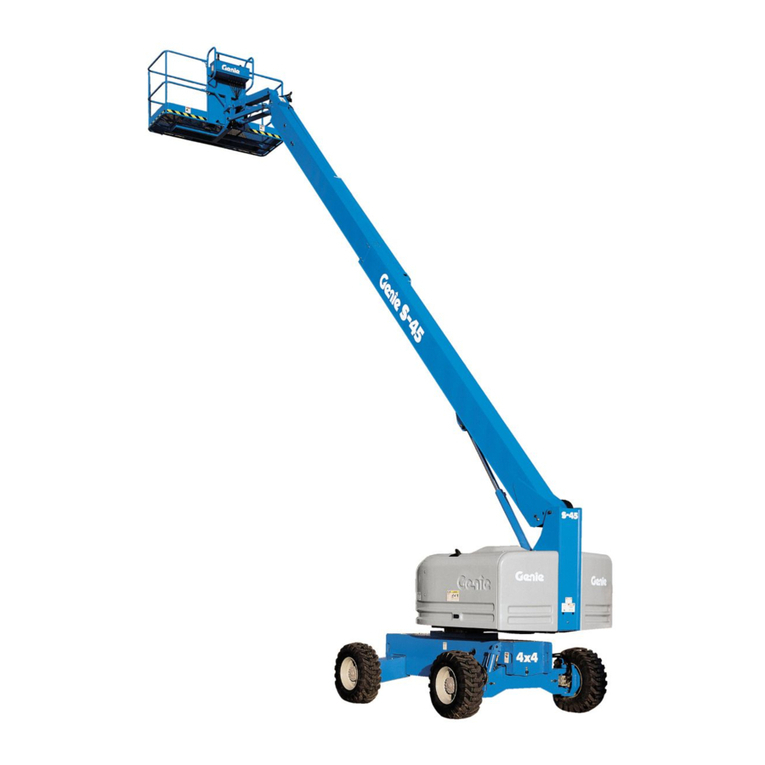
Genie Z-45 Installation and operating manual
Other Genie Lifting System manuals
Genie
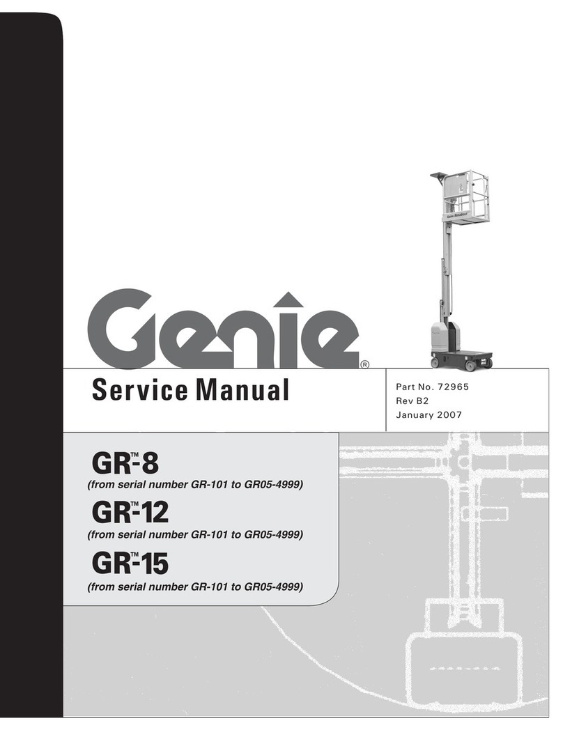
Genie Super Tower ST-20 User manual
Genie
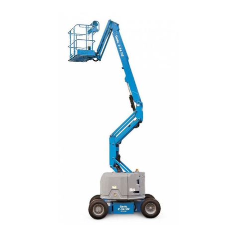
Genie Runabout GR-8 User manual
Genie
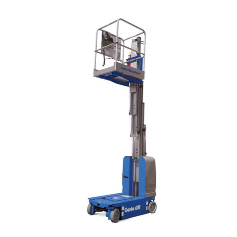
Genie Z-30/20N User manual
Genie
Genie Lift Guard GR-15 User manual

Genie
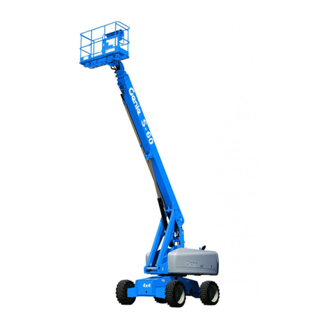
Genie GTH-2506 Stage A User manual
Genie
Genie S-65 User manual

Genie
Genie Z-45J User manual

Genie
Genie GR-20J User manual

Genie
Genie S-65 User manual

Genie
Genie S-65 User manual
Genie
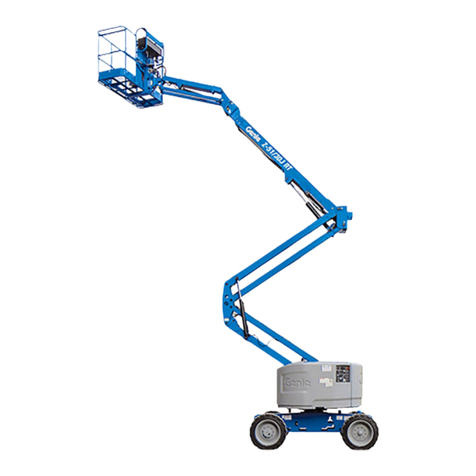
Genie Z-51/30J Setup guide
Genie
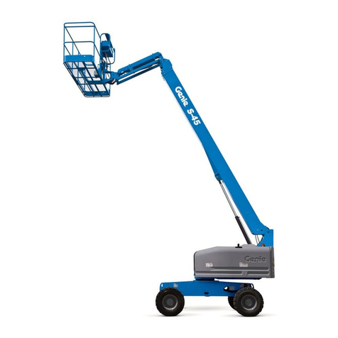
Genie S-45 XC Installation and operating manual

Genie
Genie GTH-5519 Installation and operating manual
Genie
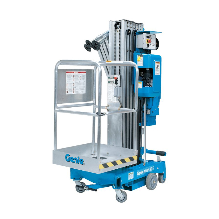
Genie AWP Super Series 114002 User manual

Genie
Genie Z-34/22 User manual
Genie
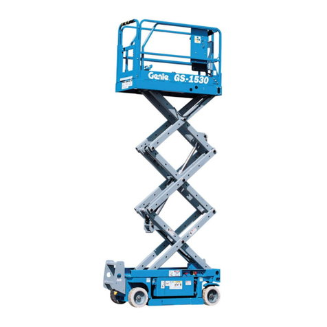
Genie GS-1930 User manual

Genie
Genie S-85 User manual
Genie
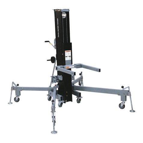
Genie Super Tower ST-20 Quick start guide

Genie
Genie GTH-1048 User manual

Genie
Genie S-40 TRAX User manual
Popular Lifting System manuals by other brands

morse
morse 82H-124 Operator's manual

Braun
Braun NL955 Series Operator's manual

haacon
haacon 1889.10 quick start guide

Protekt
Protekt AT 252 instruction manual

R. Beck Maschinenbau
R. Beck Maschinenbau HS 600 operating manual

Nova Technology International, LLC
Nova Technology International, LLC NAS Series quick start guide

Screen Technics
Screen Technics INTERFIT Vertical Up Lift instructions

Mortuary Lift
Mortuary Lift ULTIMATE 1000 instructions

Custom Equipment
Custom Equipment Hy-Brid 3 Series MAINTENANCE & TROUBLESHOOTING MANUAL

Custom Equipment
Custom Equipment Hy-Brid Lifts 2 Series Maintenance and troubleshooting manual

Hy-Brid Lifts
Hy-Brid Lifts HB-P3.6 MAINTENANCE & TROUBLESHOOTING MANUAL

BERG
BERG BeNomic EasyLeaf Technical manual

Powermate
Powermate LiftGate LG-3 Installation & operation manual

Snorkel
Snorkel TM12 Series Operator's manual

Terberg
Terberg OMNIDEKA Translation of the original instructions

Harmar Mobility
Harmar Mobility AL625 Installation & owner's manual

Rotary
Rotary SPO16 installation instructions
Ricon
Ricon Mirage F9T Service manual
