Ulvac G-Tran Series User manual

SK00-9663-E8-003-00
1. Specification
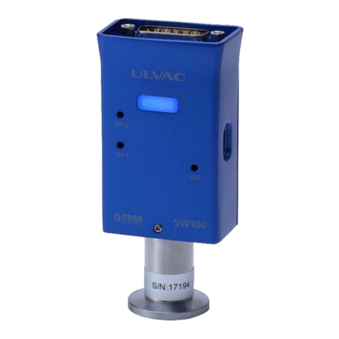
The Pirani vacuum gauge sensor unit SW100 is a vacuum gauge that can measure the
low vacuum pressure by connecting a dedicated sensor (SWP series).
SW100 is the next model to the conventional model SW1. SW100-A is compatible with
SW1-1, and SW100-R is compatible with SW1-2.
The following two types of interfaces are available. You can select the
specification that best suits the communication type.
Analog output type : SW100-A (Next model of SW1-1)
Serial communication type : SW100-R (Next model of SW1-2)
(Hereinafter, SW100 refers to both SW100-A and SW100-R.)
The I/O connector of SW100 uses a D-sub 15pin and USB Type-C.
SW100 is set with the dedicated Windows/Android application "UL-MOBI".
※"UL-MOBI" can be downloaded from our homepage or Google Play. For details,
refer to the SW100 instruction manual.
※USB Type-C can be connected to a Windows/Android device with UL-MOBI installed
using the USB cable, and can be monitored and set by UL-MOBI.
※UL-MOBI for Windows requires a Windows device with a USB device driver
installed. For details, please refer to the SW100 instruction manual.
※Settings that require UL-MOBI are SET POINT, OUTPUT, ADDRESS, BAUD RATE, and
CHECKSUM. For details, please refer to the SW100 instruction manual.
※Windows/Android devices and USB cable are not included.
Name Pirani vacuum gauge sensor unit
Type Analog output Serial communication
Model SW100-A SW100-R
Compatible sensor
※Includes the
selected one
Sensor for SW100: 1pc.
SWP-16 (NW16), SWP-25 (NW25), SWP-R1/8 (R1/8),
SWP-P18 (φ18mmtube), SWP-P15 (φ15mmtube),
SWP-CF16 (ICF034), SWP-1S (ASME BPE sanitary1”)
※See Section 6.2
Measureable
pressure range (N2)
5×10⁻² Pa to 1×10+5 Pa
Measurement
accuracy※1(N2)
1×10⁻¹ Pa to 1×10+4 Pa
:±10%
5×10⁻² Pa to 1×10⁻¹ Pa
1×10+4 Pa to 1×10+5 Pa
:±20%

SK00-9663-E8-003-00
Repeatability 1×10⁻¹ Pa to 1×10+4 Pa :±2%
Measuring gas type Indicate pressure as sensitivity to N2gas
Sampling time 5times in 60msec moving average
Measured value
output
Output voltage : DC 0V to 10V
Pressure indication: DC 1.7V to 8.0V
log output DC 1.0V/digit
Update time 50msec
Resolution 3mV
Error ±3mV
Output impedance 10Ω
Adjustment Zero point/atmospheric press
ure adjustment, adjustment
clear
Control input signal
Zero point/atmospheric pressure
adjustment, adjustment reset
Operates with open collector
input, negative logic
Control output
signal
Sensor error signal, setpoint1/2
Open collector output, negative logic
Rating: 30VMAX, 50mAMAX, 70mW
Communication D-sub15pin
USB Type-C
※USB Type-C can only be used for communication using UL-
MOBI.
Serial
communication
RS-232C/RS-485
Communication
speed
9600/19200/38400bps
Memory
function
Back up with EEPROM
LED display POWER/ERROR: Power, Error LED
SET-1 : Setpoint1 LED
SET-2 : Setpoint2 LED
Sensor material Filament: Pt
Others: SUS304 (SWP-1S: SUS316L/Ra<0.5), FeNiCo, Ni,
Au, Glass, Ceramic

SK00-9663-E8-003-00
Sensor breaking
pressure
2×10+5 Pa (absolute pressure)
※Please consider the breaking pressure of flanges and
clamps separately.
Operating
temperature range
10℃to 40℃
Operating humidity
range
15% to 80% (no condensation)
Storage temperature -20℃to 65℃(no energization, no condensation)
Sensor heating
temperature
Sensor only 150℃(without SW100)
※When heating, deviations from specifications, such as
accuracy, is observed.
※The operating temperature range of SW100 is 10℃to 40℃.
Mounting position Free
IP protection class IP30
Power supply voltage
Rated voltage: DC 24V
Voltage fluctuations: DC 14V to 30VMAX(-42/+25%)
(ripple, noise<1%)
Steady state : 2.0W
When power turned on: 4.8W
Overvoltage category: Category1
※Connect to circuits that has measures to limit the
transient overvoltages to a suffisiently low level.

SK00-9663-E8-003-00
CE standard Low Voltage Directive
EN61010-1:2010(Third Edition),A1:2019
2014/35/EU
EMC Directive EN61326-2-3:2013
2014/30/EU
Static electricity test
IEC61000-4-2:2008
Radiation electromagnetic field test
IEC61000-4-3:2006+A1:2007+A2:2010
Transient burst test
IEC61000-4-4:2004+A1:2010
Lightening surge test
IEC61000-4-5:2005
Conduction test IEC61000-4-6:2008
Commercial magnetic field test
IEC61000-4-8:2009
Radiation field intensity measurement
CISPR11:2009+A1:2010:Group 1 Class A
RoHS EN IEC63000:2018
2011/65/EU
UKCA
standard
Conforms to British legislation equivalent to EU
Directives for CE standards listed above.
I/O connector D-sub15pin connector (male), M2.6mm screw
USB Type-C
※USB Type-C can only be used for communication using UL-
MOBI.
Weight SW100 only: Approx.105g
Dimensions SW100 only: Approx.48mm×30mm×74mm ※See Section 6.1
Sensor
※See
Section
6.2
Model SWP-16 SWP-25 SWP-R1/8 SWP-P18 SWP-P15 SWP-CF16 SWP-1S
Inner
volume 7.3cm37.8cm37.6cm313.9cm3
10.0cm3
11.3cm3
8.2cm3
Weight 45g 48g 44g 43g 30g 60g 95g
accuracy※1: The accuracy after atmospheric pressure and zero point adjustment.
Please carry out atmospheric pressure and zero point adjustment before
use especially. Moreover, since calibration gas is N2, when other gas
is measured, be careful of an error of measurement.

SK00-9663-E8-003-00
Included items
P
irani vacuum gauge sensor
unit SW100 (Main unit)
1pc.
Sensor for SW100 1pc. (attached to the main unit)
Quick manual (Regular paper) 1copy
Items that need to be ordered separately
I/O connector for SW100 D-sub15pin connector (female), M2.6mm screw
※unwired
Calibration certificate Calibration certificate
JCSS calibration certificate
Inspection certificate
Traceability certificate
Display unit Model ISG1 (DC24V power supply)
Display cable Between SW100 and display unit
2m, 5m, 10m
Sensor for SW100
※See Section6.2
SWP-16 (NW16), SWP-25 (NW25),SWP-R1/8 (R1/8),
SWP-P18 (φ18mmTube),SWP-P15 (φ15mmTube),
SWP-CF16 (ICF034),
SWP-1S (ASME BPE sanitary1”)
Pirani vacuum gauge
sensor unit
SW100
Sensor for SW100
Display cable
Connector for SW100
※unwired

SK00-9663-E8-003-00
The SW100-A maintains the compatibility (OUTPUT) shown in this chapter for the
measured output voltage. By using this function, it can be replaced with SW100-A
without changing the setting to convert the measured output voltage from SW100-A
to the pressure value on the equipment side.
The setting of this function can be easily set with the dedicated application
"UL-MOBI".
OUTPUT Compatible models/conversion formula
SP1 ULVAC Pirani vacuum gauge sensor unit SP1
PSG P=10^((V-3.572)/1.286)
(P:Pressure[Pa]、V:Measured output voltage[V])
APG P=10^(V-4) (P:Pressure[Pa]、V:Measured output voltage[V])
After purchase, please check the instruction manual of SW100 for both new
installation and replacement, and set and connect. When used as a compatible unit,
the performance of SW100-A may be limited, so please read the instruction manual.
※"UL-MOBI" can be downloaded from our homepage or Google Play. For details,
refer to the SW100 instruction manual.
※To set SW100, a Windows/Android device with the application "UL-MOBI" installed
and a USB cable (SW100 side: Type-C) are required.
※UL-MOBI for Windows requires a Windows device with a USB device driver
installed. For details, please refer to the SW100 instruction manual.
※ULVAC display unit ISG1 does not support the measured value output voltage
conversion formula of PSG and APG.
※If the specifications of the I/O connector are different, you need to change
the connector.
※If you set the SW100 on the equipment side, you do not need to use the
compatibility function in this section.

SK00-9663-E8-003-00
Analog output type SW100-A (D-sub15pin (male), M2.6mm screw)
Pin
number This unit Function
1 Power supply Power supply for driving this unit
DC 14V to 30V
2 Sensor error
It outputs a signal when an error occurs,
such as filament disconnection.
Lo、DC 30VMAX, 50mAMAX, 70mW
3 Setpoint1 It
outputs a signal when setpoint1 is
operating.
Lo、DC 30VMAX、50mAMAX、70mW
5 Adjustment input
Input a signal when adjusting zero point or
atmospheric pressure.
Operates when short with GND
8 Measure signal output It outputs a measured value.
DC 0V to 10V
9 Power supply GND Ground for the power supply
11 Setpoint2
It outputs a signal when setpoint2 is
operating.
Lo、DC 30VMAX, 50mAMAX, 70mW
15 Signal GND Ground for the output signal
Case Frame ground Ground of frame
※When SP1, PSG, APG is selected as OUTPUT (see Section 1.4 of this manual), it
is different from the above pin layout. For details, refer to the SW100
instruction manual.

SK00-9663-E8-003-00
Serial communication type SW100-R (D-sub15pin (male), M2.6mm screw)
Pin
number This unit Function
1 Power supply Power supply for driving this unit
DC 14V to 30V
2 Sensor error
It outputs a signal when an error occurs,
such as filament disconnection.
Lo、DC 30VMAX, 50mAMAX, 70mW
3 Setpoint1
It outputs a signal when setpoint1 is
operating.
Lo、DC 30VMAX、50mAMAX、70mW
4 RS232C RxD RxD of RS-232C
5 Terminating resistor
for RS485
Terminating resistor for RS-485
Connect with pin13.
6 RS232C TxD TxD of RS-232C
8 Measured value output It outputs a measured value.
DC 0V to 10V
9 Power Supply GND Ground for the power supply
10 RS485- Minus of RS-485
11 Setpoint1
It outputs a signal when setpoint2 is
operating.
Lo、DC 30VMAX、50mAMAX、70mW
12 RS485+ Plus of RS-485
13 RS485+
for connecting the
terminating resistor
Terminating resistor for RS-485.
Connect with pin5.
15 Signal GND Ground for the output signal
Case Frame ground Ground of frame

SK00-9663-E8-003-00
Measurement value output
This unit outputs the measured value as a voltage signal of DC 0V to 10V.
I/O connector: 8pin[Measured value output+]-15pin[GND]
※When SP1, PSG, APG is selected as OUTPUT (see Section 1.4 of this manual), the
specifications are followed instead of the voltage output and pin sign in this
section. For details, refer to the SW100 instruction manual.
Use the following formula to convert to pressure.
P = 10 ^ ( V - C ) ⇔V = log P + C
P: Pressure V: Measured output voltage[V] C: Conversion factor
Pressure unit C: Conversion factor
Pa 3
Torr 5.1249
mbar 5
※When SP1, PSG, APG is selected as OUTPUT (see Section 1.4 of this manual),
follow the respective conversion formulas instead of the pressure conversion
formulas in this section. For details, refer to the SW100 instruction manual.
Measurement value output
The table below shows the measurement value output under some conditions that
can occur during measurement.
Operating state Measurement value output voltage
Normal measurement DC 1.7V to 8.0V
Higher than atmospheric pressure DC 8.0V or more
Below measurable lower limit DC 1.0V to 1.7V
Filament disconnection DC 9.0V or more
4 seconds after startup DC 8.1V
※When SP1, PSG, APG is selected as OUTPUT (see Section 1.4 of this manual), the
value will correspond to each conversion formula, not the output voltage in
this section. For details, refer to the SW100 instruction manual.

SK00-9663-E8-003-00
Control input/output signal
Photocoupler ratings [30VMAX, 50mAMAX, 70mW]
Fig. 3-1 SW100 output signal internal circuit diagram
Control input signal (Analog output type SW100-A only)
Fig. 3-2 SW100-A input signal internal circuit diagram
+5V
+24V
A
12
A
12
A
12
2:ERROR signal ON/OFF
3:SETPOINT signal-1 ON/OFF
15:GND
11:SETPOINT signal-2 ON/OFF
Internal circuit PLC or PC
Internal circuit
Power supply
+5 V
5:ADJUST input
15: GND
Internal circuit

SK00-9663-E8-003-00
How to use serial communication (Serial communication type SW100-R only)
RS-232C RS-485
Two-wire type
Full duplex Half duplex
Asynchronous
ASC11 code
Data bit length 8 bits
Stop bit 1 bit
No parity
Maximum cable length 15 m Maximum cable length 30 m
Maximum connection: 1 Maximum connections: 32
(including host)
9600/19200/38400 bps 9600/19200/38400 bps
Settings
RS-232C connection diagram
An example of RS-232C connection is shown below. The host side is a D-sub 9pin.
RS-485 without terminating resistor (Example)
Example) USB serial interface USB-485 manufactured by NATIONAL INSTRUMENTS.
This unit pin No. Host pin No.
RxD 4 2 RxD
TxD 6 3
GND 15 5GND
TxD
This unit pin No. Host pin No.
RS485+ 12 4RxD+
RS485-
8TxD+
10 5RxD-
GND 15 1GND
9TxD-

SK00-9663-E8-003-00
RS-485 with terminating resistor (Example)
Example) USB serial interface USB-485 manufactured by NATIONAL INSTRUMENTS.
If the number of RS-485 connections is large, the total length of the connection
cable is more than 15m, or communication errors frequently occur, install a
terminating resistor in the terminating equipment.
Standard data format
The following is the standard data format for sending and receiving.
: AD0 AD1 CMD D0 …… Dn SH SL CHKH CHKL CR
: Colon
AD0 Device address, higher 4bit (0~9)
AD1 Device address, lower 4bit (0~9)
CMD Commands (upper/lower case-sensitive)
D0 Data 4bit (0~9, A~F)
Dn Data 4bit (0~9, A~F)
SH Higher bits of status (4bit)
SL Lower bits of status (4bit)
CHKH Higher bits of checksum (4bit) (0~9, A~F)
CHKL Lower bits of checksum (4bit) (0~9, A~F)
CR Carriage return
Commands consist of alphanumeric uppercase and lowercase
characters.
The checksum is the exclusive OR sum (XOR) from AD0 to SL.
Convert all in ASCII code hexadecimal.
Host pin No.This unit pin No.
RxD+
RS485+ 12 4
8TxD+
RS485- 10
GND
RS485+ 13
RxD-
9TxD-
5
15 1GND
terminating
resistor
5

SK00-9663-E8-003-00
Command Description Command Description
D Read measured value and
status
T Reading the model and
software version
ZER Zero point adjustment 1R Read Setpoint1 value
ATM Atmospheric pressure
adjustment
2R Read Setpoint2 value
CLR Clear the zero point and
atmospheric pressure
adjustment
1W Write Setpoint1 value
SR Reading status 2W Write Setpoint2 value
SW Writing status
Command (Excerpt): Reading measured value and status
Command
: AD0 AD1 D CHKH CHKL CR
Return format from this unit to PC
:
AD0
AD1
D
X
.
X
X
E
±
X
X
SH
SL
CHKH
CHKL
CR
「X.XXE±XX」is the measured pressure value.
e.g.1) 3.00E+03 ⇒3.00×10+3
e.g.2) 5.00E+00 ⇒5.00×10+0
e.g.3) 4.00E-01 ⇒4.00×10⁻¹
When 「E.EEE+EE」is returned.: Sensor error
When 「F.FFE+FF」is returned.: The measurement range is exceeded
or filament is off.
Please refer to Section4.3 for SH and SL.

SK00-9663-E8-003-00
Warranty
This unit is strictly inspected in-house before it is shipped out. However, should
any failure that is our responsible occur, such as defects in manufacturing or
accidents during transportation, please contact the Components division of ULVAC,
Inc. or the nearest sales office or distributor. We will repair or replace it free
of charge.
Warranty covered items
1) Pirani vacuum gauge sensor unit SW100
2) Sensor immediately after delivery
Warranty period
One year from the date of delivery
Warranty scope
1) Domestic transaction: A product that is damaged due to the problem during
transportation at the time of delivery.
2) Direct export transaction: A product that is damaged due to problem during
transportation at the time of delivery. The warranty scope specified in the
latest INCOTERMS shall be applied.
3) A product that does not meet the basic specifications of this unit even
though it is used within the operating conditions of the basic specifications,
such as the measurement pressure, the operating temperature limits, and the
operating power supply.
Warranty support
1) Domestic transaction: We will send you a replacement. Or we will ask you to
send the unit to the nearest service center or us for repair. If you need
local support, please contact the Components division of ULVAC, Inc. or your
nearest sales office or distributor.
2) Direct export transaction: We will send you a replacement. Or we will ask
you to send the unit to the nearest service center or us for repair. Please
note that the customer is responsible for return shipping costs.

SK00-9663-E8-003-00
Disclaimer
1) Products that are out of warranty period.
2) Failures and malfunctions caused by natural disasters such as fires, storms,
floods, earthquakes, and lightning, and force majeure disasters such as wars.
3) Failure or malfunction caused by careless handling or improper use.
4) Products that are modified, disassembled, or repaired without our consent.
5) Defects and damages under an abnormal environment (Strong electromagnetic
field, radiation environment, high temperature, high humidity, flammable gas
atmosphere, corrosive gas atmosphere, dust).
6) Failures and malfunctions caused by noise.
7) Secondary damage caused to you by product defects or a third party's claim
that we infringe a patent.
8) Sensor unit in use (Lifespan due to the use, measurement error due to
contamination).
9) Sensor cable in use (Cable disconnection or poor contact due to improper
installation).
Other
1) If there is a separate contract or memorandum regarding specifications
besides this instruction manual, the contents of the contract or memorandum
will be followed.
2) When exporting this product outside of Japan, please notify us and take
necessary procedures according to Export Related Legislation such as the
Foreign Exchange and Foreign Trade Act.
3) Should you have any questions or need consults about this product, please
check the model and the serial number and contact the nearest sales office,
distributor, or the components division of ULVAC, Inc.
4) Please note that the contents of this instruction manual are subject to
change without notice.

SK00-9663-E8-003-00
Diagrams

SK00-9663-E8-003-00
SWP (Sensor for SW100) dimensions
46
40
Φ30
SWP-16
NW16
66
60
47
41
Φ40
77
83
Φ18
SWP-25
NW25
SWP-R1/8
R1/8
SWP-P18
Φ18tube
45
51
50.4
65
Φ15
59
65
59
Φ33.8
SWP-P15
Φ15tube
SWP-CF16
CF16(ICF034)
SWP-1S
ASME BPE sanitary1"
Other manuals for G-Tran Series
11
This manual suits for next models
2
Other Ulvac Measuring Instrument manuals

Ulvac
Ulvac G-Tran Series User manual

Ulvac
Ulvac HELIOT 301 User manual

Ulvac
Ulvac SPU User manual

Ulvac
Ulvac G-TRAN CCMT-D Series User manual

Ulvac
Ulvac G-TRAN SW100-A User manual

Ulvac
Ulvac G-Tran Series User manual

Ulvac
Ulvac GP-1000G User manual

Ulvac
Ulvac GI-M2 Installation guide

Ulvac
Ulvac GP-1G User manual

Ulvac
Ulvac MBD Series User manual