Cod. 06590091000MR/B
T.2 KEY RENTENTION (OPTIONAL
FUNCTIONALITY) TRANSFORMATION CLÉ
NON EXTRACTIBLE TRANSFORMATIE NIET
VERWIJDERBARE SLEUTE
6
P
3
T.3 SCREWS AND SQUARE
SPINDLE CUTTING COUPE CARRÉE/
LANGUETTE ET VIS INSNIJDING STIFT/
KLEP EN SCHROEVEN
S+10 mm
S (Max = 100)
S-10 mm
9
7
4
M
L
9
7
M= S+10 mm L= S-13 mm M= S+10 mm L= S-13 mm M= S+10 mm L= S-13 mm Z= 100 mm
M= S+10 mm L= S-13 mm M= S+10 mm L= S-13 mm M= S+10 mm L= S-13 mm Z= 100 mm
561
581 571
372 - 376
377 - 378
379 - 389
1438 - 573
S (Max =Z)
T.7
When the control device is operated, the
latch must withdraw smoothly and travel
back freely when released.
En actionnant la commande, le pêne
demi-tour doit rentrer sans forcer et revenir
librement lors du relâchement.
Als u de bediening inschakelt, moet de
schoot moeiteloos naar binnen gaan en vlot
weer naar buiten komen.
9
Put attention; one xing above the lock and
one through the euro prole cut out.
Attention; relatif à la xation, a vis au-
dessus de la serrure et l’un par le prol de
l’euro cylindre.
Aandacht: voor het bevestigen, een schroef
boven het slot, een door het gat van de
cilinder.
T.8
10
For optimal drilling, place the cam at 45°; it
is possible, however, to use cylinders with
0° to 22° cam
Pour un poinçonnement optimal, positionner
la came à 45° ; il est aussi possible de
monter des cylindres avec des cames à 0°
ou 22°.
Voor een correcte werking dien u de kam op
45° te plaatsen. Het is echter ook mogelijk
om cilinders te plaatsen met een kam op 0°
of 22°.
COMPONENTS COMPOSANTS ONDERDELEN
NOTE: references to the exploded view are printed
on the gures to help identify each component
NOTE : les références de la vue éclatée sont
indiquées sur les gures pour reconnaître le
composant
OPMERKING: de referenties zijn aangebracht
op de afbeeldingen om het onderdeel te kunnen
herkennen
Component (3) not Included with OAD.
Supplied within 560/570/580 devices. Composant (3) ne pas inclus avecAOD. Equipé
dans les dispositifs anti panique 560/570/580 Bestanddeel (3) niet Inbegrepen bij OAD. Geleverd
met 560/570/580 paniek apparaten
2
5
7
9
36
1
OP
9
1
3
6
P
7
58
8
2
4
Ref. Q.ty Componenti/ Components/ Composants / Componentes
11 Handle / Poignée / Deurkruk
21 Main case / Boîtier principal / Hoofdslotkast
31Outside op. device follower (Required only for 560/570/580) / Panneton commande externe (Requis
uniquement pour 560/570/580) / Mechanisme bediening aan de buitenzijde (Alleen vereist voor 560/570/580)
41 Cylinder with key / Cylindre avec clé / Cilinder met sleutel
51 Handle xing screw / Vis de xation de la poignée / Bevestigingsschroef handgreep
61 Key rotation stop / Axe de blocage de la clé / Blokkeringstift sleutel
71 Square spindle 8 mm / Carré 8 mm / Staafjes 8 mm
82 Rod / Colonnette / Kolom
92Fixing screw / Vis de xation / Bevestigingsschroef
2
7
9
36
1
OP
5
9
8
82
5
7
9
3
6
1
OP
9
8
8
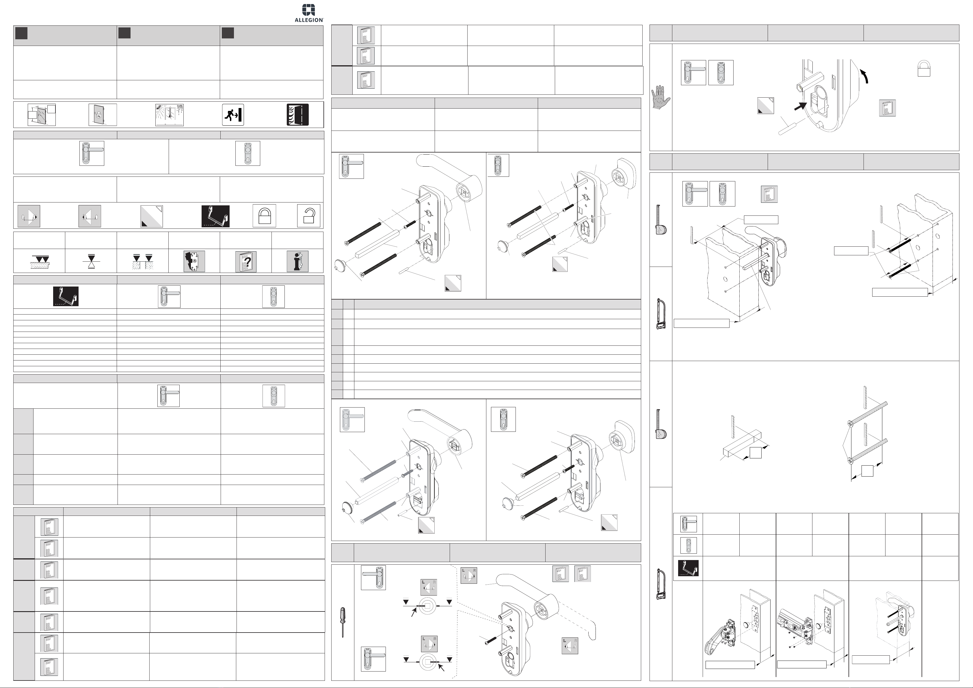
T.1 CHANGE OF HAND –
MARK CHECKING INVERSION MAIN–
CONTRÔLE MARQUES
OMDRAAIEN
OPENINGSRICHTING -
CONTROLE TEKENS
L
R
R
L
12
1
5
B
B
EN OUTSIDE OPERATION
DEVICES FOR PANIC EXIT
DEVICES - Installer’s instruction sheet
COMMANDES EXTERNES POUR
POIGNEES ANTI-PANIQUES
Feuillet d’instructions pour installateur
BEDIENING AAN DE BUITENZIJDE
VOOR PANIEKSLUITING
Handleiding voor de monteur
WARNING
These product characteristics are essentially
important to ensure personal safety. No product
modications may be introduced other than those
described in this instruction sheet.
AVERTISSEMENTS
Les caractéristiques de ce produit ont une
importance extrême pour la sécurité des personnes
et il n’est donc pas consenti d’apporter des
modications au produit, autres que celles qui sont
décrites dans ces instructions.
WAARSCHUWING
De kenmerken van dit product besteden veel aan-
dacht aan de veiligheid van personen. Het is niet toe-
gestaan wijzigingen aan het product aan te brengen
die niet beschreven staan in deze handleiding.
Limit values prescribed by the UNI EN 1125
standard with extension. This product is certied
for use on standard and/or re doors.
Valeurs limite prescrites par la UNI EN 1125
avec
majoration
. Le produit est adapté pour l’utilisation sur
les portes standard et/ou coupe-feu.
Grenswaarden voorgeschreven door UNI EN 1125
met uitbreiding. Het product is geschikt voor het
gebruik op standaard- en/of brandwerende deuren.
> 200
(400 max) -20
+100 °C
Max.
1,6 m
Max.
3,5 m
SYMBOLS SYMBOLES SYMBOLEN
Art. 1413.KE - 1413.KE.NC
Art. 1413.LE - 1413.LE.NC
Right-handed door (R).
Left-handed door (L).
Optional functional (OPT).
Panic exit device item no.
Porte main droite (R).
Porte main gauche (L).
Fonction optionnelle (OPT).
N. article poignée anti-panique .
Rechtsdraaiende deur (R).
Linksdraaiende deur (L).
Optionele functie (OPT).
N° artikel panieksluiting.
R
L
P
Check atness
Contrôle planéité
Vlakheid controleren
Place
Poser
Plaatsen
Align
Aligner
Afstellen
Use template
Utilisation gabarit
Gebruik sjabloon
See notes
Voir textes notes
Zie beschrijving
See instructions
Voir instructions
Handleiding
Installation with panic exit device Association avec poignée anti-panique Combinatie met sluiting
372 ■ ■
376 ■ ■
377 ■ ■
378 ■ ■
379 ■ ■
389 ■ ■
1438 ■ ■
561 ■ ■
571 ■ ■
573 ■ ■
581 ■ ■
Instruction index Validité tables instructions Geldigheid illustraties handleiding
Table Number / Description
Numéro / Description table
Nummer / Beschrijving illustratie
T.1
Change of hand
– Mark checking
Inversion main-Contrôle marques
Omdraaien openingsrichting - Controle
tekens
■ ■
T.2 Non-removable key change
Transformation clé non extractible
Transformatie niet verwijderbare sleutel ■ ■
T.3
Screw and Square spindle/tab cutting
Coupe fouillot carrée/languette, vis
Insnijding stift/klep, schroeven ■ ■
T.4 Drilling / Perçage / Uitboren ■ ■
T.5 Fixing and nal checks
Fixation et vérications nales
Bevestigen en eindcontroles ■ ■
Ref / Réf / Ref Notes Textes notes Verklaring
T.1
Insert the handle x it with the screw 5Introduire le groupe poignée et xer en
vissant les vis 5 à fond. Plaats de handgreep 5 en draai hem
volledig vast met de schroeven.
Rotate until notch Bis aligned with opposite
reference mark. Tourner jusqu’à aligner l’encoche Bavec la
référence opposée. Draaien totdat de inkeping Bin lijn ligt met
het linker referentiepunt.
T.2
Optional functionality - Insert Key. Rotate to
locked position. Remove Key. Insert Pin.
Fonctionnalité optionnelle - Insérer la clé.
Tourner en position verrouillée. Retirer la
clé. Insérer la tige
Optionele functie - Steek de sleutel. Draaien
om vergrendelde positie. Verwijderen de
sleutel. Steek Pin
T.3
4
Insert Spindle into OAD, measure door
thickness cut spindle from OAD face to
door thickness +10mm. Cut screws to door
thickness -10mm.
Insérer la broche dans OAD. Pour la coupe
de la broche à l’épaisseur de la porte +
10mm. Pour la coupe de la Vis à épaisseur
de la porte -10mm
Plaats vierkantstift in OAD. Meten deurdikte
cut vierkantstift as van OAD aangezicht tot
deurdikte + 10mm. Snijd schroeven tot deur
dikte -10mm
T.4
Place template in position and drill holes as
specied.
Placer le gabarit en position et les trous de
forage comme spécié.
Plaats de sjablonen op zijn plaats en
doorboren zoals gespeciceerd.
T.5
Insert square spindle 10 into panic exit
device follower 4. Introduire le fouillot carrée 10 dans le
fouillot 4de la poignée anti-panique. Steek de stift 10 in het mechanisme 4 van
de sluiting.
Check that internal mechanisms can move
freely (shorten square spindle if needed).
Vérier le mouvement libre des
mécanismes internes (éventuellement
raccourcir la longueur du carrée).
Controleer of de interne mechanismen vrij
kunnen bewegen (maak eventueel de stift
korter).


