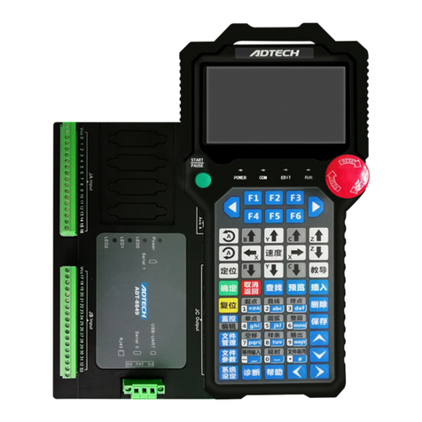
Adtech ADT-RC400 User manual

ADTECH Robotic Drive System
ADT-RC400
User Manual
(Electrical Wiring)

Information of manual
I
Information of manual
This manual is edited By ADTECH (SHENZHEN) TECHNOLOGY CO., LTD.
The editors of this manual:
The version of this manual:V2.0
Copy Right
All parts of this manual, property right owned by Adtech (Shenzhen) Technology
Co.,LTD (hereinafter referred to as) to all, without permission, no unit or individual is not any
imitation, copying, copying or translation. Position this guide without warranty of any kind,
expressed or implied. As mentioned by this manual or its product information, arising out of,
directly or indirectly, information flow, loss of interest or career ending, and its employees
will not take any responsibility. In addition, the products and information mentioned in this
manual are for reference only, subject to updates without notice.
All rights reserved, do not reproducing.
ADTECH (SHENZHEN) TECHNOLOGY CO., LT

II
Range of manual
This is the first manual of QC400 drive robotic control system including full description,
drive control for the initial users, to help users select reasonable motor type; followed this
specification for drive control electrical wiring between the machine and the robot in detail.
Precautions
※Transport and storage
Product package iteration of no more than six;
It is not available in the product box on the climb, stand or place heavy objects;
Cannot use drag the cables attached to the product or handling products;
No collision, scratching the Panel and display screen;
Product box should avoid wet, dry and the rain.
※Opening inspection
After opening the packaging please confirm whether you purchased the product;
Check whether the products in transit damage;
Control list identifies whether the part is complete, there is no damage;
Product model, lack accessory or transport damage, please contact with me.
※Wiring
To participate in connections and inspection personnel must have the appropriate
skills for professionals;
Products must be reliable earthling, grounding resistance should be less than 4
ohms; you cannot use the neutral (zero line) instead of ground;
Wiring must be properly and firmly, so as not to lead to product failure or
unexpected consequences;
And surge absorption diode must be connected in accordance with the
regulations are connected with, otherwise you will damage;
Plug or open the front of the chassis, you must cut off the power supply.
※Maintenance
Must cut off the power before repair or replacement of components
Should check the fault when a short circuit or overload occurs, troubleshooting
before they can restart
Cannot pass off frequently, if required to re-apply after a power failure,
separated by at least 1 minute
※Others

III
Do not open the Cabinet without permission,
Long when not in use, please cut off the power.
To pay special attention not to let dust, iron powder into the controllers.
Output relay if the use of solid state relays shall be freewheeling diode in
parallel in the relay coil. Check if the power supply meets the requirements, put
an end to the controller is burnt out.
Life of the controller temperature has much to do with the environment, if the
processing temperature is too high, please install the cooling fan. Controller
working ambient temperature range between 0 ℃-60 ℃.
To avoid high temperatures, humidity, dust or corrosive gas environments.
Shake strongly to add buffer rubber rails.
※Maintenance
Under normal conditions of use (environment conditions: average 30 ℃, load
80%, running 12 hours a day), please press the following items for routine
checks and regular checks.
Daily Check
Daily
Recognition of environmental temperature,
humidity, dust and foreign bodies
●There are no abnormal vibrations,
sound
●Ventilation holes without being
clogged with yarn and other
Period Check
1 year
●Substantial part is loose or not
●Terminal block damage

IV
Since the robot system is more complex, dangerous. The manual records and
security-related precautions, please strictly observe transactions as recorded.
Safety Precautions and mark
Mark
Mark meaning
Danger
Use wrongly, it will lead to a dangerous situation,
causing serious injury or death
note
Use wrongly,It will lead to a dangerous situation that
may cause personal injury or damage to equipment
which caused material damage.
Ban
Absolutely unenforceable
!
Forcibly
Must be implemented
Danger
Please do not use this system in the flammable and explosive environment.
Likely to cause injuries or fire.
Please follow the instructions drawings or wiring.
Prone to electrical shock and damage the
motor.
In an energized state, do not arbitrarily pull the plug, in the operating state, do not touch
the robot operation site.
Easy electric shock, causing personal injury.
Energized state, not for wiring, maintenance and other operations, be sure to power at
least 5 minutes before proceeding.

V
Easy electric shock.
Please be sure to take a reliable grounding between the drive and the robot body.
When the fault occurs easily lead to electric
shock, fire incident, easy to trigger errors.
Non professional personnel, please do not open the drive and control one machine shell,
please do not use hand to touch the drive and control of internal components
Easy electric shock
In the case of power, do not touch the power plug of the integrated machine.
Easy electric shock.
Please do not damage, the weight of cable or cable suspended load
Easy electric shock
The energized state, do not plug the drive terminal machine control on
Easy electric shock and short circuit
Running state, do not pull out the terminal on the one machine
Easy electric shock and short circuit

VI
Attention
Please pay attention to the drive and control of the motor and the heat of the peripheral
equipment.
Easy to burn.
When a fault occurs, the power supply is cut off, the cause is identified and removed, and
the low speed running equipment should be removed.
If there are adverse factors, easy to cause
false action.
When using the controller and the robot body, it cannot exceed the scope of its
specification.
Easily cause damage to the product.
When the robot is moved, it needs to be fixed with the attached fixed tool.
To prevent the lifting arm, due to accidents.
The installation, operation, maintenance and inspection before, be sure to read the
instructions carefully, according to the operating instructions in step.
Easy electric shock, fire
Power supply voltage, power capacity must be specified by the company's specifications.
Improper use of equipment failure, easy to
cause a fire.
Please correct use of the correct control of each other to drive one machine and robot.
Prone to failure

VII
Should be regularly on the implementation of the robotics drive system maintenance and
inspection operations.
Neglect of maintenance and inspection is an
important cause of equipment failure and
accidents.
Please do not put heavy objects on the product.
Easily cause damage
Please correct the wiring in the instruction manual.
The wrong wiring way is easy to cause the
robot or the drive control one machine
damage or cause a fire.
When an exception occurs, please stop.
Easy electric shock, personal injury, fire
Need to repair, please contact our company, please do not disassemble.
Easy cause trouble.
Do not impact
Easy cause trouble

VIII
Ban
In the course of the robot's movement, no person is allowed to stand in the robot action
area.
There will be a major injury accident.
Equipment to prevent the movement of the robot in the workplace.
When the device is abnormal, it is easy to
cause damage.
The emergency stop switch on the handheld display device is prohibited.
Robots in an accident or is not running
properly, you need an emergency stop
switch, stop operation of the equipment.
There is no correct operation of the prohibition on the instruction manual.
Incorrect operation will bring about the
incorrect operation of the equipment.
Other personnel outside the operating personnel to close to the equipment
Touching the dangerous area can cause the
injury or the major accident.
When an accident, to cut off the power supply, clear reasons.
When there are bad reasons, the robot may
have a wrong action, causing adverse
consequences.
Users are prohibited to carry out parts of the exchange and transformation.

IX
Will reduce the system performance and
may malfunction
Please do not remove the cleaning.
Easy to cause fire, easy to get electric shock.
Please don't make the product stored in the leaks, water, and other harmful gases in the
environment.
Prone to failure
Forced
!
Please keep the sun out of the sun.
!
Easy cause trouble
Please use the specified range.
!
Easily cause burn, failure
Equipment protection cover must be shut off during operation.
!
Open the protective cover will have electric
shock, the disabled.
Operator to go through the full training.
!
Incorrect operation will cause the device to
malfunction, resulting in disability or major
disaster.
If the robot is not in accordance with the specified direction of action, press the emergency
stop, stop the equipment operation.
!
Accidents and failures.

X
Power cord must be used with the specified wire.
!
Prone to fire and failure.

XI
Safety regulations
Before starting the run, we need to know all the tasks of robot in accordance with the
program to be executed;
Robots run in automatic mode, personnel are not allowed to enter any of its movement
reach areas;
When the need for programming, testing and maintenance work, the robot shall be placed
under manual mode;
When debugging personnel enter the robot work area, he shall carry a teach pendant, to
prevent others from malfunction;
When the robot does not work for a long time, the fixture should not place items; it shall
be empty machine;
After a power outage, the main power on the robot should shut down timely, and remove
the clamp on the work piece.

XII
Catalogue
1. System Introduction and Overview of Functions ................................................................14
1.1 System Components...................................................................................................14
1.2 Robotics Drive System Instructions...........................................................................14
1.3 FlexPendant Introduction...........................................................................................15
1.4 Feature Overview.......................................................................................................16
1.4.1 Technical Parameters .......................................................................................16
1.4.2 Product Configuration......................................................................................18
1.4.3 Basic Specifications.........................................................................................18
2. External Wiring....................................................................................................................18
2.1 System Configuration ................................................................................................18
2.2 Product Description of Each Part...............................................................................21
External Profile of 72Pins Robot Controller.......................................................21
External Profile of 48Pins Robot Controller.......................................................22
3. Power Cord Connect............................................................................................................23
Main Power Supply.............................................................................................23
IO Power Supply.................................................................................................24
4. Motor Wiring Terminals.......................................................................................................25
4.1 Diagrams for Two Kinds of Motor’s Terminal <72Pin>/<48Pin>.............................25
72Pin Heavy Load Connector ................................................................................25
48Pin Heavy Load Connector ................................................................................25
4.2 MOTOR Terminal<72Pin> Signal Description.........................................................26
26-Pins Encoder Definition.................................................................................28
20-Pins Power Definition....................................................................................29
16-Pins IO Line Definition .................................................................................30
IO Wiring Diagram for 72Pin Robot ..................................................................31
4.3 Connection Instances of Motors for 72Pin ................................................................32
4.3.1 Panasonic Motor Wiring Instance....................................................................32
4.3.2 Tamagawa Motor Wiring Instance...................................................................36

XIII
4.3.3 Sanyo Electric Wiring Instance........................................................................39
4.3.4 SANKYO Electric Wiring Instance.................................................................43
4.4 Signals’ Definition for <48Pin> Motor Terminal ......................................................47
Definition of 16Pin Encoder...............................................................................49
Definition of two-channels External Encoders...................................................51
Definition of 19Pin Power..................................................................................52
Definition of 16Pin or 20Pin IO..........................................................................53
IO Wiring Diagram for 48Pin Robot ..................................................................55
4.5 Connection Instances of Motors for 48Pin ................................................................56
5. Digital Input and Output Interfaces .....................................................................................72
5.1 Digital Inputs .............................................................................................................72
5.1.1 Input Interface Definition and Pin Functions...................................................72
5.1.2 Digital Input Schematic Diagram ....................................................................74
5.2 Digital Output Interface.............................................................................................76
5.2.1 Output Interface Definition and Pin Functions................................................76
5.2.2 Schematic Diagram of a Digital Output...........................................................78
6. Communication Port............................................................................................................81
6.1 COM1 Port Wire Drawing.........................................................................................81
6.2 COM2 Port Connection .............................................................................................83
6.3 LAN Port....................................................................................................................84
6.4 USB Interface.............................................................................................................85
6.5 Product Installation Size Chart ..................................................................................85

14
1. System Introduction and Overview of Functions
1.1 System Components
Drive machine control system mainly consists of the following three parts:
1)QC400 drive control system
2)Handheld FlexPendant
3)Connecting Cables
1.2 Robotics Drive System Instructions
Figure 1-1 shows the schematic side of robotic drive controller(QC400);
The system machine integrated several CPUs (ARM9 + DSP + FPGA), which are
control module, high-performance servo drive module, I/O module, display module,
communication module as a whole;
Interfaces include motor power cable, encoder cable, IO cable, and power cable and
so on.
1. Interface of power , encoder and IO cables;
2. Handheld Flex Pendant connector;
3. External IO board interface;
4. 190~240V Power interface
Figure 1-1 QC400 schematic side

15
1.3 FlexPendant Introduction
Front view of Flexpedant is shown in Figure 1-2:
Figure 1-2 Front view of FlexPendant
Back view of Flexpedant is shown in Figure 1-3:
Three Position
Switch
Figure 1-3 Back view of FlexPendant

16
1.4 Feature Overview
1.4.1 Technical Parameters
Table 1-1 Drive control integrated machine technical parameters
model
ADT-QC400
Handheld
FlexPendant
screen
color display with a resolution of 800 * 600
programming language
G-code
Teach mode
Manual Teach
Size/weight
355mm*248mm*70mm/2KG
Drive
Control
System
QC400
Drive
control
function
control axes
4 axis
support motor
type
supports all-digital AC servo motors (for
example: Sanyo, Panasonic, Tamagawa,
Adtech and other brands)
position
detection
method
detection encoder (incremental / absolute)
power
single-axis power below 1.2KW, four-axis
total power below 3KW
External
input
Standard IO
34 road (with opto-coupler isolation)
External
output
Standard IO
27 Road (6 relays, 21 Road NPN open
collector)
Motion control function
circular interpolation, continuous path, the
trajectory to follow, all kinds of acceleration
and deceleration, etc.
Coordinate system
joint coordinate system, world coordinate

17
system, the tool coordinate system, User
Coordinate System
Cartesian coordinate
display mode
Cartesian coordinate display mode, the joint
coordinate
External communication
RS-232:2CH(9 pin)、 Ethernet:1CH
(100Mbps/10Mbps)USB2.0:2CH
Dimensions / Weight
length (including aviation head) 517mm *
Width 160mm * high 273mm / 20KG
Power
Single-phase within AC200V~230V,50Hz

18
1.4.2 Product Configuration
Table 1-2 Product configurations
Name
Descriptions
Qty
QC400
host controller
1 set
Plug
the host power supply plug
1 pcs
USB
USB download cable
1 pcs(optional)
serial line
9 female-female serial line
1 pcs(optional)
Connecting cable
Cable host and motor, encoder cable
1 pcs
Input connecting cable
Input Wiring 37-pin host input port junction
1 pcs
Input board
I/O input board
1 piece
Output connecting cable
Output Wiring 25pin output port junction a host
1 pcs
output board
I/O output board
1 piece
RPB06
handheld FlexPendant
1 set(optional)
1.4.3 Basic Specifications
Table 1-3 Basic specifications
Climatic conditions
Temperature
Working
-5℃~50℃
Storage and transportation
-30℃~70℃
Relative humidity
Working
20%~90%(℃)
Storage and transportation
10%~95%(℃)
Atmospheric pressure
86Kpa~106Kpa
2. External Wiring
2.1 System Configuration
Before using the drive control integrated machine, you need to complete the system
wiring, wiring distributed as follows:

19
Peripheral Devices
SCARA Robot
FlexPendant
IO Board
QC400 Controller
Figure 2-1 System Configuration
Other manuals for ADT-RC400
1
Table of contents
Other Adtech Control System manuals
Adtech
Adtech 4 Series User manual
Adtech
Adtech ADT-DK300A User manual
Adtech
Adtech CNC9 Series User manual
Adtech
Adtech ZM430A-A01 User manual

Adtech
Adtech 4 Series Mounting instructions
Adtech
Adtech ADT-CNC4220 User manual
Adtech
Adtech Q2BYG806DK User manual
Adtech
Adtech ADT-09 Series User manual
Adtech
Adtech NCT-04 User manual
Adtech
Adtech ADTECH4 CNC Series User manual
