o
,:e
CL
î1,
u
u,
J
C'
z,
rg
o
z.
J
ts
l
I
I
43024
4,5024
Mícrointerrutîore
dirallentamento
in
chiusura
Derele|atio
nn iî |os
witch for clt]
sure
Micrinterruptor
dereduccion
delamarcha
encierr€
Vite
senzafine
Worm-gear
Tornillo
sinfin
Slitta
azionamento
microinterruttore
Mìcroswitch
actLral
nn {urìne
r
Corredera
accionamiento
microinlerrupîor
Madrevite
screw-nul
Tornilo
tuèrca
Gruppomicrointérruttore
di
rallèntamento
e
distopin
apenufa
Micrzswitch
unitfarslLrwrrld
andstopping
dutingapenilV
Grupo
microinterruptor
de
deceleracióny dèparada
enapenura
Supportocavo
CabJe
f0ber
Soporte
paracables
Astapona
mícrointerru$ore
Suppon
plare
mtcroswttch
Chapa
porta
microínterruptor
Madrevite
SLxerv-nul
Tornillo
tuerca
Viti
difissaggio
f ixing $rews
Tornillons
deFijación
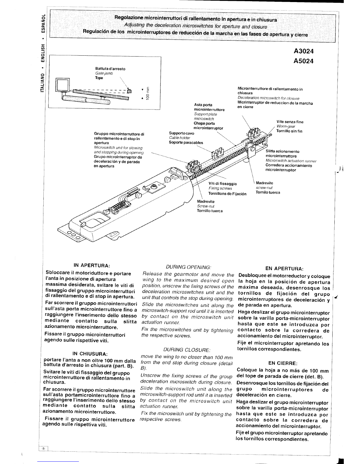
IN
APEBTURA:
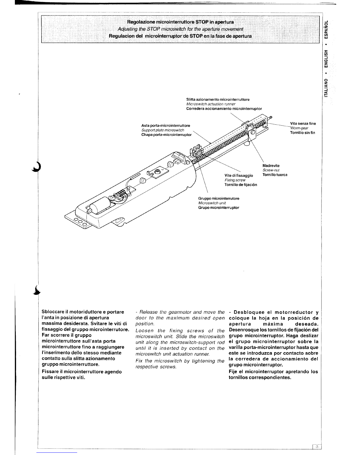
Sbloccare
il motoriduttore
e portare
l'anta
inposizione
diapertura
massima
desiderata,
svitare
leviti di
fissaggio
delgruppomicrointerruttori
di rallentamento
edi stop inaperlura.
Far
scorrere
ilgruppo
microinterruttori
sull'astaportamicroinlerruttore
fino a
raggiungere
I'inserimenlo
dellostesso
mediante contatto sufla slitta
azionamento
microi
nterruttore.
Fissare
il
gruppomicrointerrultori
agendo
sulle
rispettive
viti.
Fissare
il gruppo microinterruttore
agendo
sulle
rispettiva
viti.
INCHIUSURA:
portare
l'anta
a nonoltre100
mm dalla
battuta
d'arresto
inchiusura
lpart-
È1.
Svilare
le
vitidifissaggio
del
gruppo
mrcrotnlerruttore
dirallenlamento
in
chiusura.
Far
scorrere
il
gruppo
microinterruttore
sull'astaportamicrointerruitore
fino a
raggiungere
l'inserimento
dello
stesso
mediante contalto sulla slitta
azionamenlo
microinterruttore.
DTJRING
OPENING:
Releasefhe geannator
ancl
move the
wing to the maximunt desired apen
position,unsctewthefixing screws
of the
decelerationmicroswitches unit ancl the
unttthatcontrolsthestopduringopening.
Slide the microswitchesunit alona the
nticroswitch-support
rodunttl
itis inierted
by contact on the nticroswitch unit
actuati?n runner.
Fix the nìcroswitches unit by tightening
the respective
screws.
DURING CLOSURE:
move lhe wingto no closer than lA0 mnt
fram the end stap during closure (delail
B)
Unscrew the fixing screws af the group
decelerction microswitchduring clasure.
Slide the mlcraswitclt unit alana the
microswitch-support
roduntrlit tsiníerbd
by c0ntact on the microswitch unit
actuatiotl rL!nner.
F'ix
themicroswitch
unitby tightening
the
respective screws.
EN
APEBTUFIA:
Desbloquee
el
motorreductor
ycoloque
la hoja en la posición
de aperlura
méxima
deseada,
desenrosque
los
tornillos de fijación del grupo
microinterruptores
de deceleración
y
de parada
enapertura.
Haga
deslizar
el
grupo
microinterruptor
sobre la varillaporta-microinterruptor
hasta que este se iniroduzca por
contacto sobre la corredera de
accionamiento
del
microinterruptor.
Fijeel microinterruptor
apretando
los
tornil
los
correspondientes.
EN
CIERRE:
Coloque
la hoja
a no màs
de 100
mm
deltopede parada
de
cierre(det.
B).
Desenrosque
lostornillos
de
fijación
del
grup0 microinterruptores de
deceleración
en cierre.
Haga
deslizar
el
grupo
microinterruptor
sobre la varillaporta-microinterruptor
hasta que este se introduzca por
contacto sobre la corredera de
accionamiento
delmicrointerruptor.
Fije
el
grupo
microinterruptor
apretando
los
tornillos
correspondientes.
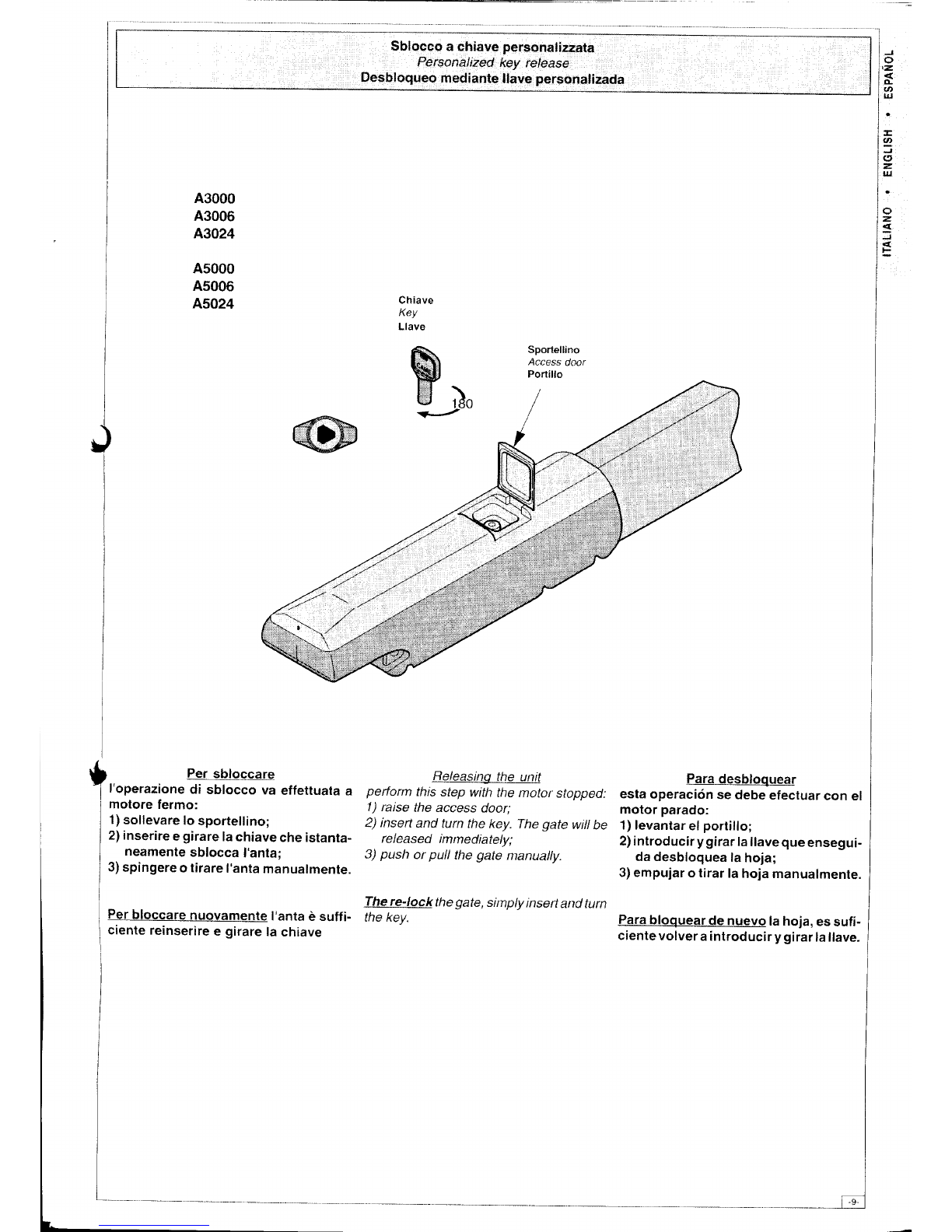
Regolazione
microintèrruttori
di rallentamento
inapertura
einchiusura
Adiusting
thedeceleration
microswitches
for aperture
and closure
Regulación de los microinterruptores de reducción de la marcha en lasfases de apertura y cierre
Batluta
d'arrèsto
Gate
jafib
Tope .\ .b F
t
O
rp
z
---
iól
I