AllSportSystems MICROBAY 10W User manual

AllSportSystems, Inc.©2021
Table of Contents
ITEMS YOU WILL NEED 4
MEASURING AND CUTTING EMT POLES 5
ITEMS PROVIDED BY ALLSPORTSYSTEMS 6
BUILDING THE FRAME 7
SCREEN INSTALLATION 12
INSTALL THE BLACK OUT TRIM 16
INSTALL ANGLED SIDE NETTING (Optional Upgrade) 19
SAFETY PRECAUTIONS 20
APPENDIX A - SideRite™ Cable Assembly 21
APPENDIX B - EMT POLE SCHEMATIC 24
Page 3 of 24 Table of Contents Last Revised 8/25/2021

AllSportSystems, Inc.©2021
ITEMS YOU WILL NEED
Tools/Equipment
● Six foot step ladder
● Screwdriver
● Hacksaw/Tubing Cutter (or ask the store to cut the EMT poles for you)
● Scissors/Utility Knife
● Measuring Tape
● Pencil
Building Materials Not Included
The following items are not included and must be obtained locally.
●Metal EMT Poles
1” diameter, 10’ long EMT conduit poles from any major local hardware store. See
Appendix B for EMT pole schematic and more details on type and size of pole to
purchase. For quantity and lengths needed see chart on the following page.
Trade Size Designator: 1” diameter,
common EMT 10-ft Conduit
●Strut Channel
For customers ordering SkyBridge™ you will need at least one 10’ long Unistrut™ or
SuperStrut™ channel [1 5/8" x 7/8"] or [1 5/8" x 13/16"]. They can
be purchased from any major local hardware store. SkyBridge™
customers must substitute the front EMT pole for a Strut Channel.
Be sure to read the SkyBridge™ user guide for more details.
Page 4 of 24 Table of Contents Last Revised 8/25/2021

AllSportSystems, Inc.©2021
MEASURING AND CUTTING EMT POLES
NOTE: SkyBridge™ customers should first review the SkyBridge™ setup guide as it will
reduce the number of EMT poles needed. The size of your MicroBay will determine the
number of poles needed, see chart below.
Frame Size
Number of
Poles
Needed
Cut poles as follows:
MicroBay
10W by 8H
8 ea 10’ poles
Height: 4 poles cut to 7’9” ea.
Width: 3 poles cut to 9’9”ea.
Depth: 1 pole cut into 2 ea. 1’9” (top sides) and
2 ea. 3’0” poles (bottom legs)
MicroBay
12W by 9H
9 ea 10’ poles
Height: 4 poles each cut to 8’9” in length.
Width: 3 poles at 10’ in length (no cuts needed)
Extenders: 1 pole cut into 3 sections 1’9” in length.
Depth: 1 pole cut into 2 sections 1’9” (top sides) and
2 ea 3’0” poles (bottom legs)
Poles for custom sized MicroBay™:
If you have ordered a custom dimension bay use the information below to calculate the number of
10ft EMT poles needed and cut them to the proper length:
HEIGHT
POLES
You will need 4 ea 10ft EMT poles - cut ea 3 inches shorter than your finished
height
WIDTH AND
EXTENDER
POLES
For bay under 10ft - you will need 3 ea 10ft EMT poles - cut ea poles 3 inches
shorter than your finished width.
For custom size greater than 10ft - you will need 4 ea 10ft EMT poles - 3 ea poles
will not need to be cut (leave them at 10ft each). The 4th pole should be cut into 4
sections to extend the 10ft poles to your finished width (-) minus 3” inches.
(i.e. a 13ft wide bay would require three (3) 10ft poles plus three (3) extender poles
ea 2ft 9in long)
DEPTH
POLES
You should not reduce the depth of the MicroBay
Depth: 1 pole cut into 2 ea. 1’9” poles (top sides) and
2 ea 3’0” poles (bottom legs)
Note: Each corner bracket adds approximately 1.5” to the size of your enclosure. Therefore, once
poles and brackets are assembled an additional 3” will be added to the finished width, height and
depth of your enclosure. Therefore, all poles are cut 3” shorter than the finished height, width, or
depth of the enclosure. If you have ordered a custom sized enclosure make note of this factor
when cutting your poles.
Page 5 of 24 Table of Contents Last Revised 8/25/2021

AllSportSystems, Inc.©2021
BUILDING THE FRAME
Standard frame assembly shown below, see Step 1B if you have purchased SkyBridge™
Brackets.
Step 1A - Standard Frame Assembly Diagram
See Step 2 for frame assembly instructions. Note that couplers are only needed for
MicroBay™ greater than 10 feet wide.
*Poles are purchased separately from local hardware stores.
Note: Once poles are inserted into the corner brackets 3” will be added to the width and
height of your frame. Therefore, as indicated above, all poles are cut 3” shorter than
desired height, width, or depth of the frame. If you are customizing the size of your frame
take note of this factor.
Page 7 of 24 Table of Contents Last Revised 8/25/2021

AllSportSystems, Inc.©2021
Step 1B - OPTIONAL SkyBridge™ Upgrade Diagram
Refer to this diagram if you have purchased the SkyBridge™ upgrade. See also the
SkyBridge™ installation guide. See Step 2 for frame assembly instructions. Note that EMT
and Strut Couplers are only needed for a MicroBay™ greater than 10 feet wide.
*Poles and Strut Channel are purchased separately from local hardware stores.
Note: Once poles are inserted into the corner brackets 3” will be added to the width and
height of your frame. Therefore, as indicated above, all poles and strut are cut 3” shorter
than desired height, width, or depth of the frame. If you are customizing the size of your
frame take note of this factor.
Page 8 of 24 Table of Contents Last Revised 8/25/2021

AllSportSystems, Inc.©2021
Step 2 - Build the frame
Two persons recommended and use of a stepladder. Position eye bolts inward. Verify correct width
and depth when tightening connectors (may need to back poles slightly out of connectors to reach
correct dimension).
For bays greater than 10ft wide,
add extender poles to each of the
three width poles using couplers.
For SkyBridge™
Use Strut Channel and Strut
Coupler for one of the width
poles.
Add two 3-Ways to a width pole to
form the bottom rear pole.
Insert two leg poles into rear
3-Ways to form the frame bottom.
Insert two height poles into back
3-ways.
Add two 3-Ways to the top of the
rear height poles
Insert top rear width pole to
complete the back of the frame.
Insert two upper depth poles into
the back top 3-ways.
Slide two T-Connectors on each of the leg
poles.
Before installing the last two height poles,
add two T-Connectors to the top of each
pole.
Insert two height poles into the
T-Connectors on the legs while sliding the
top T-Connectors onto the upper depth
poles. Leave the lower T-Connectors
loose so that they will slide on the legs.
Slide the poles toward the back until they
are approximately 14” from the rear height
poles.
Add two L-Corners to each end of the front
width pole.
For SkyBridge™
No L-Corners are needed.
Insert the final front width pole into the two
ends of the upper depth poles to complete
the frame.
For SkyBridge™
Use the SkyBridge™ bracket and strut.
See SkyBridge™ setup guide for
instructions on installing this pole
Page 9 of 24 Table of Contents Last Revised 8/25/2021

AllSportSystems, Inc.©2021
Step 3 - Check All Connections And Verify Dimensions
● Proper position of the poles and brackets for the microbay frame are shown below.
Note that the bottom legs will extend out 36” and the top 24”. Verify that all connectors
are tight and outside dimensions are correct.
10 WIDE BY 8 TALL MICROBAY (shown here)
or
12 WIDE BY 9 TALL MICROBAY
TOP: 24” Front to Back
BOTTOM: 36” legs
CHECK ALL CONNECTIONS TO BE SURE THEY ARE TIGHTENED DOWN
AND VERIFY OUTSIDE DIMENSIONS
8’ High x 10’ Wide x 2’ Deep or 9’ High x 12’ Wide x 2’ Deep
Page 10 of 24 Table of Contents Last Revised 8/25/2021

AllSportSystems, Inc.©2021
Step 4 - Install The Black Leg Wrappers
Wrap the legs with the Black leg wrapper
sleeves. The sleeves will wrap around the
legs and then velcro to themselves.
Add the included 1” STIFF Adhesive Velcro
to the top of your screen pole or strut.
Excess velcro can be trimmed with a utility
knife or scissors.
● An extra length of SOFT Adhesive Velcro is included in each MicroBay. Set this length
of velcro aside, as it will be used later
Page 11 of 24 Table of Contents Last Revised 8/25/2021

AllSportSystems, Inc.©2021
SCREEN INSTALLATION
Step 5 - Install Cabling For Siderite™ Tension Kit
Note: The SideRite™ tension kit comes standard and will keep tension on your screen and waves
to a minimum. Cables first need to be assembled, See APPENDIX A - SideRite™ Cable Assembly .
After cable assembly, see the steps below to install the cables on the enclosure.
● On each side of the frame loop the SideRite™ cabling around the upper depth pole
and bottom leg. Position the cable to the front until it rests in the elbow of the top
L-Bracket. Loop the cable under the bottom leg.
● Attach the hook end of the turnbuckle to the other end of the cable. Tighten the cable
by twisting the turnbuckle causing the cable to shorten. The cable should have good
tension.
Page 12 of 24 Table of Contents Last Revised 8/25/2021

AllSportSystems, Inc.©2021
Step 6 - Before hanging the screen
Creases: Screen may have creases from being folded during shipment. These creases will lighten
over time. If you wish, you may steam or iron the screen prior to hanging.
Cleaning: Over time your screen may become stained or marked from ball impacts. Your screen
can be placed in the washing machine. Be sure to use MILD detergent on a gentle cycle.
DO NOT USE BLEACH OR PLACE SCREEN IN DRYER
IDENTIFY THE FRONT SIDE of your screen:
The AllSportSystems Logo and smooth face of the grommets will always be on the front side.
Additionally, velcro is sewn along the right and left edge of the screen front. Blackout side
panels attach to this velcro (see Blackout installation section).
Page 13 of 24 Table of Contents Last Revised 8/25/2021

AllSportSystems, Inc.©2021
Step 7 - Hang Screen
Screen Front can be identified by the AllSportSystems logo on the bottom left corner of the
screen, by the 2” Velcro sewn along the sides, and by the smooth grommet faces.
DO NOT INSTALL THE SCREEN BACKWARDS!
IT WILL SIGNIFICANTLY REDUCE THE LIFE OF THE SCREEN!
Hang screen using cable ties. Loosely attach the screen to the front screen pole.
Page 14 of 24 Table of Contents Last Revised 8/25/2021

AllSportSystems, Inc.©2021
Step 8 - Attach screen to SideRite™ tensioning kit
The SideRite™ cables should already be installed. Loosely thread cable ties through the side
grommets and around both of the SideRite™ cables.
Tip: Do not tighten the zip ties until they have been installed on both sides of the screen.
After both sides are loosely tied to their SideRite™ cables, gradually tighten the ties on the left and
right sides, creating even tension that centers the screen in the enclosure.
IF YOU HAVE PURCHASED SKYGUARD NETTING FOR YOUR
MICROBAY, IT SHOULD NOW BE INSTALLED
Page 15 of 24 Table of Contents Last Revised 8/25/2021

AllSportSystems, Inc.©2021
INSTALL THE BLACK OUT TRIM
Step 9 - Install Side Panels
SIDE PANELS ARE INTERCHANGEABLE , AND CAN BE USED ON
EITHER SIDE WITH OR WITHOUT SKYGUARD NETTING.
Side panels are interchangeable and can be
used on either side.
SkyGuard netting customers should
install side panels with the notch
facing the front of the enclosure
(shown in photo).
Customers who have not purchased
the SkyGuard netting, should install
the panels on opposite sides so that
the notch faces the back of the
enclosure.
Attach the side panels to the Microbay using
the included zip ties.
The leading edge of the side panel will
attach to the 2” Velcro to the face of your
screen. Make sure the screen edge is flat
and even.
● Take the SOFT Adhesive Velcro that was set aside and cut it in half.
● Attach the velcro pieces to the bottom of the back height pole, so that the side
panels can velcro to them, keeping them from hanging away from the cage.
Page 16 of 24 Table of Contents Last Revised 8/25/2021

AllSportSystems, Inc.©2021
Step 11 - Install The Top Panel
● The Top Panel will velcro to the velcro strip that you installed along the top of your
screen pole.
● After attaching it to the velcro on the front, loosely secure the back of the Top Panel to
the upper back pole with the included zip ties. Do not tighten them yet.
● Align and attach the left and right flaps of the Top Panel to the matching velcro strip on
the side panels.
Take time now to ensure the Top Panel is centered on the MicroBay. It may be
necessary to adjust and realign the velcro along the front for a proper fit. Add more
tension to the zip ties once the top panel is in place and centered.
Page 17 of 24 Table of Contents Last Revised 8/25/2021

AllSportSystems, Inc.©2021
Step 12 - Install Back Panel (Optional Upgrade)
This step only applies if you have purchased the BlackOut Rear Panel. The panel includes
grommets along the top and sides.
● First, use cable ties to hang the Back Panel from the rear width pole.
● Next, use cable ties to attach the Back Panel sides to the rear corner poles.
Page 18 of 24 Table of Contents Last Revised 8/25/2021

AllSportSystems, Inc.©2021
INSTALL ANGLED SIDE NETTING (Optional Upgrade)
Step 13 - Install triangle side nets
● Attach Netting to Velcro along Side Panels.
● Extra netting at the top can drape underneath the Top Panel into the inside of the
enclosure.
● Fill the provided sandbags with sand or some other object to give it weight and use
cable ties to attach the sandbag to the other pointed end of the netting. Pull the netting
out in front of the screen and slightly wider than the frame.
Page 19 of 24 Table of Contents Last Revised 8/25/2021

AllSportSystems, Inc.©2021
SAFETY PRECAUTIONS
If you have not purchased SkyGuard netting, we strongly recommend using “Almost Golf
Balls” or foam balls rather than real golf balls when using your MicroBay. This is a safety
recommendation only. The MicroBay screen is fully capable of handling full golf shots from
real golf balls.
YOUR MICROBAY SYSTEM IS NOW
COMPLETE AND READY FOR USE!
Page 20 of 24 Table of Contents Last Revised 8/25/2021
This manual suits for next models
1
Table of contents
Other AllSportSystems Video Gaming Accessories manuals

AllSportSystems
AllSportSystems SUPERBAY 10W User manual

AllSportSystems
AllSportSystems MICROBAY User manual
AllSportSystems
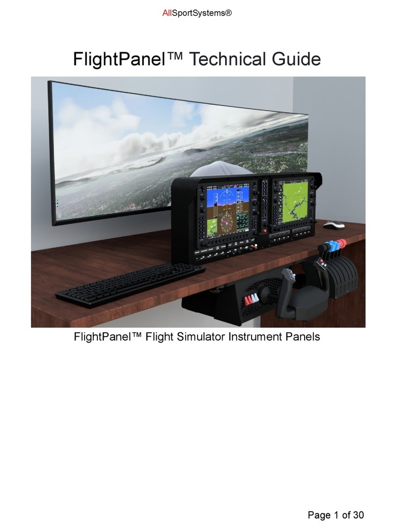
AllSportSystems FlightPanel Quick start guide

AllSportSystems
AllSportSystems SUPERBAY User manual

AllSportSystems
AllSportSystems SUPERBAY Series User manual
AllSportSystems
AllSportSystems HANGING MINIBAY User manual
AllSportSystems
AllSportSystems SkyGuard User manual
AllSportSystems
AllSportSystems MICROBAY User manual


