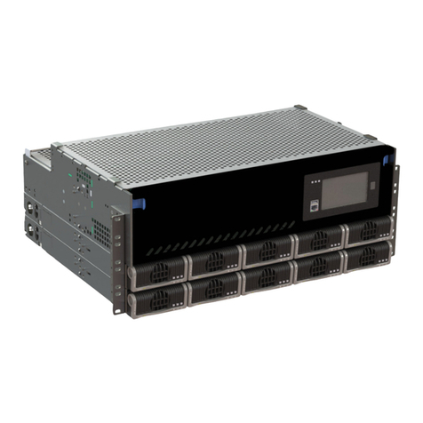
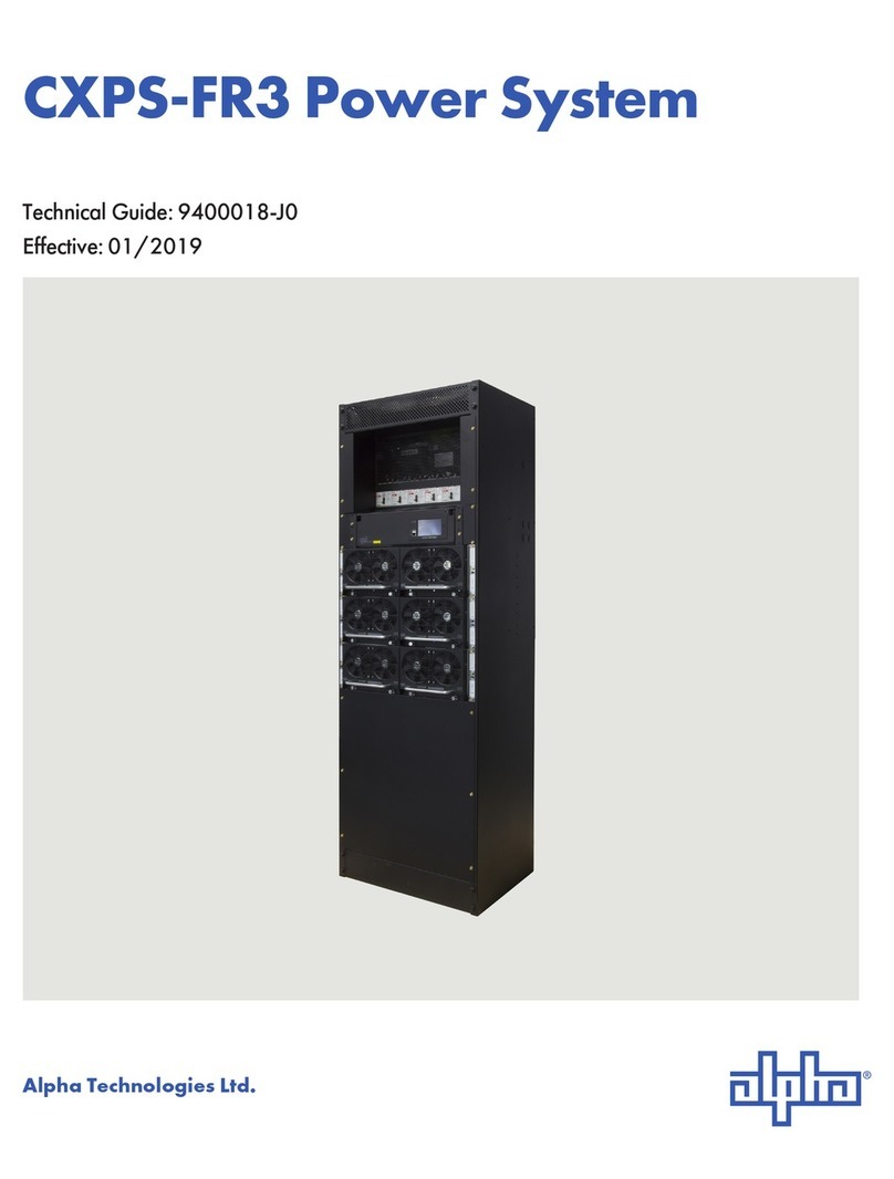
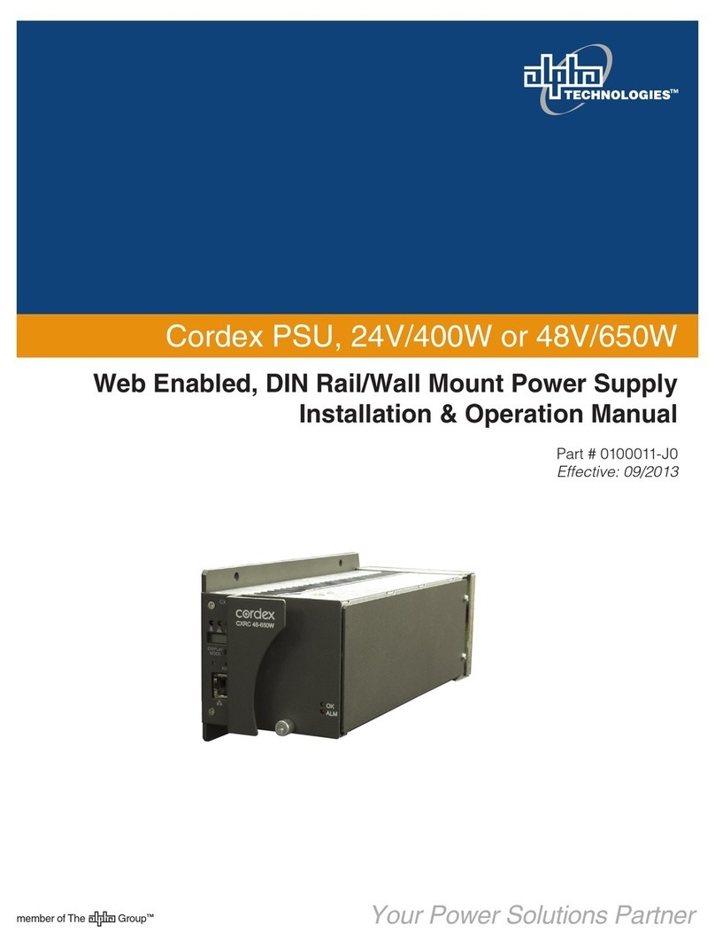
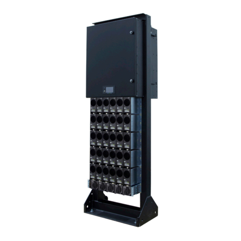
Alpha Technologies CXPS-E101 User manual

Technical Guide: 0540569-J0
Effective: 08/2018
CXPS-E101 Power Systems
Alpha Technologies Ltd.


CXPS-E101
100A and 225A -48Vdc Power Systems
For technical support, contact Alpha Technologies:
Canada and USA: 1-888-462-7487
International: +1-604-436-5547
Copyright
Copyright © 2018 Alpha Technologies Ltd. All rights reserved. Alpha is a registered trademark of Alpha Technologies.
No part of this documentation shall be reproduced, stored in a retrieval system, translated, transcribed, or transmitted
in any form or by any means manual, electric, electronic, electromechanical, chemical, optical, or otherwise without
prior explicit written permission from Alpha Technologies.
This document, the software it describes, and the information and know-how they contain constitute the proprietary,
confidential and valuable trade secret information of Alpha Technologies, and may not be used for any unauthorized
purpose, or disclosed to others without the prior written permission of Alpha Technologies.
The material contained in this document is for information only and is subject to change without notice. While reason-
able efforts have been made in the preparation of this document to assure its accuracy, Alpha Technologies assumes
no liability resulting from errors or omissions in this document, or from the use of the information contained herein.
Alpha Technologies reserves the right to make changes in the product design without reservation and without notifi-
cation to its users.
Alpha shall not be held liable for any damage or injury involving its enclosures, power
supplies, generators, batteries, or other hardware if used or operated in any manner or
subject to any condition inconsistent with its intended purpose, or if installed or oper-
ated in an unapproved manner, or improperly maintained.
Photographs contained in this manual are for illustrative purposes only. These photo-
graphs may not match your installation.
NOTE:
Operator is cautioned to review the drawings and illustrations contained in this manual
before proceeding. If there are questions regarding the safe operation of this powering
system, contact Alpha Technologies or your nearest Alpha representative.
NOTE:
NOTE:

Table of Contents
1. Safety....................................................................................................................................5
1.1 Safety Symbols .......................................................................................................................... 5
1.2 General Safety ........................................................................................................................... 5
1.3 Mechanical Safety...................................................................................................................... 5
1.4 Electrical Safety ......................................................................................................................... 6
1.5 Battery Safety ............................................................................................................................ 6
2. Introduction ...........................................................................................................................7
2.1 Scope of the Manual .................................................................................................................. 7
2.2 Product Overview....................................................................................................................... 7
2.3 System Congurations............................................................................................................... 8
3. Specications........................................................................................................................9
4. Features..............................................................................................................................11
4.1 CXDM-E1 Distribution Panel.....................................................................................................11
4.2 Overview of the CXCM1+ Controller........................................................................................ 13
4.3 Overview of the CXCM1 HP Controller.................................................................................... 15
4.4 Cordex CXRF-HP Rectier ...................................................................................................... 17
5. Inspection............................................................................................................................20
5.1 Packing Materials..................................................................................................................... 20
5.2 Check for Damage ................................................................................................................... 20
5.3 General Receipt of Shipment................................................................................................... 20
6. Installation...........................................................................................................................21
6.1 Safety Precautions................................................................................................................... 21
6.2 Tools Required ......................................................................................................................... 21
6.3 Power System Assembly and Mounting................................................................................... 21
6.4 Rectier Module Insertion/Removal ......................................................................................... 22
6.5 Breaker Installation .................................................................................................................. 23
6.6 Battery Installation ................................................................................................................... 24
6.7 Battery Maintenance Report .................................................................................................... 25

7. Wiring..................................................................................................................................26
7.1 Installation Notes ..................................................................................................................... 26
7.2 Ground Sizing .......................................................................................................................... 27
7.3 AC Feeder Protection/Sizing.................................................................................................... 27
7.4 AC Wiring ................................................................................................................................. 27
7.5 DC Wiring................................................................................................................................. 28
7.6 System and Battery Connections............................................................................................. 28
7.7 Chassis Ground and Return Bus Bar Connections.................................................................. 29
7.8 Distribution Cabling.................................................................................................................. 30
7.9 Alarm and Signal Connections................................................................................................. 31
7.10 Signal Wiring Connections for Controller ............................................................................... 31
7.11 CAN Serial Ports .................................................................................................................... 33
7.12 Network Connection and Remote Communications via Controller ........................................ 33
8. System Startup ...................................................................................................................34
8.1 Check System Connections..................................................................................................... 34
8.2 Verify AC Input and Power Up Rectier Shelf .......................................................................... 34
8.3 Check Battery Polarity and Connect the Batteries................................................................... 34
8.4 Controller Reset ....................................................................................................................... 34
8.5 LVD Control.............................................................................................................................. 35
9. Rectier Modes and Factory Defaults.................................................................................36
9.1 Rectier Modes ........................................................................................................................ 36
9.2 Factory Ranges and Defaults .................................................................................................. 37
10. Maintenance .....................................................................................................................38
10.1 Rectiers ................................................................................................................................ 38
10.2 Batteries................................................................................................................................. 38
10.3 Troubleshooting ..................................................................................................................... 39
11. Warranty Statement and Service Information ...................................................................40
12. Acronyms and Denitions .................................................................................................41
13. Certication.......................................................................................................................42

List of Figures
Figure 1 — Front view of the CXPS-E101 48V 225A........................................................................ 7
Figure 2 — CXPS-E101 100A Conguration .................................................................................... 8
Figure 3 — CXPS-E101 225A Conguration .................................................................................... 8
Figure 4 — CXPS-E101 225A (CXCM1 HP) Conguration .............................................................. 8
Figure 5 — Front Panel Status Indicators........................................................................................11
Figure 6 — CXDM-E1 Rear Output Connections ............................................................................11
Figure 7 — LVBD Override Switch (front cover removed) .............................................................. 12
Figure 8 — CXCM1+ Controller Front Panel .................................................................................. 13
Figure 9 — CXCM1 HP Controller Front Panel .............................................................................. 15
Figure 10 — In-Shelf Controller Dashboard Screens ..................................................................... 15
Figure 11 — In-Shelf Controller Full Menu...................................................................................... 16
Figure 12 — In-Shelf Controller Buttons: Vertical Mount ................................................................ 16
Figure 13 — In-Shelf Controller Buttons: Horizontal Mount............................................................ 16
Figure 14 — Rectier Front Panel .................................................................................................. 17
Figure 15 — Breaker Installation .................................................................................................... 23
Figure 16 — Breaker Removal Tools .............................................................................................. 23
Figure 17 — Ground and Return Busbar Connections ................................................................... 29
Figure 18 — Battery / Rectier Bus Bar Connections..................................................................... 29
Figure 19 — Battery, Load, and Return Connection Locations....................................................... 30
Figure 20 — Alarm and Signal Connections ................................................................................... 31
Figure 21 — Relay Connections ..................................................................................................... 31
Figure 22 — Digital Input Connection Method ................................................................................ 32
Figure 23 — LVD LED Status Indicators......................................................................................... 35

50540569-J0 Rev F
1. Safety
SAVE THESE INSTRUCTIONS: This manual contains important safety instructions that must
be followed during the installation, servicing, and maintenance of the product. Keep it in a safe place. Review the
drawings and illustrations contained in this manual before proceeding. If there are any questions regarding the safe
installation or operation of this product, contact Alpha Technologies or the nearest Alpha representative. Save this
document for future reference.
1.1 Safety Symbols
To reduce the risk of injury or death, and to ensure the continued safe operation of this product, the following sym-
bols have been placed throughout this manual. Where these symbols appear, use extra care and attention.
The use of ATTENTION indicates specic regulatory/code requirements that may aect the
placement of equipment and /or installation procedures.
WARNING!
WARNING presents safety information to PREVENT INJURY OR DEATH to personnel.
Warnings are indicated by a shock hazard icon, the word WARNING, and a rule beneath
which the information appears.
CAUTION!
CAUTION indicates safety information intended to PREVENT DAMAGE to material or
equipment. Cautions are designated with a yellow warning triangle, the word CAUTION,
and a rule beneath which the information appears.
NOTE:
A NOTE provides additional information to help complete a specic task or procedure.
Notes are designated with a checkmark, the word NOTE, and a rule beneath which the
information appears
HOT!
The use of HOT presents safety information to PREVENT BURNS to the technician or
user.
1.2 General Safety
1.3 Mechanical Safety
• Keep hands and tools clear of fans. Fans are thermostatically controlled and switch on automatically.
• Power supplies can reach extreme temperatures under load.
• Use caution around sheet metal components and sharp edges.
WARNING!
This system is designed to be installed in a restricted access location that is inacces-
sible to the general public.

0540569-J0 Rev F
6
1.4 Electrical Safety
WARNING!
WARNING!
WARNING!
• Before working with any live battery or power system, follow these precautions:
a. Remove all metallic jewelry, such as watches, rings, metal rimmed glasses, or necklaces.
b. Wear safety glasses with side shields at all times during the installation.
c. Use OSHA approved insulated hand tools.
Lethal voltages are present within the power system. Always assume that an electrical
connection or conductor is energized. Check the circuit with a voltmeter with respect to
the grounded portion of the enclosure (both AC and DC) before performing any installa-
tion or removal procedure.
• Do not work alone under hazardous conditions.
• A licensed electrician is required to install permanently wired equipment. Input voltages can range up to 480 Vac.
Ensure that the utility power is disconnected and locked out before performing any installation or removal proce-
dure.
• Ensure that no liquids or wet clothes come into contact with internal components.
• Hazardous electrically live parts inside this unit are energized from the batteries even when the AC input power is
disconnected.
Follow battery manufacturer’s safety recommendations when working around battery
systems. Do not smoke or introduce an open ame when batteries (especially vented
batteries) are charging. When charging, batteries vent hydrogen gas, which can ex-
plode.
• Batteries are hazardous to the environment and should be disposed at a recycling facility. Consult the battery
manufacturer for recommended local authorized recyclers.
Hazardous voltages are present at the input of power systems. The DC output from rec-
tiers and batteries, though not dangerous in voltage, has a high short-circuit current
capacity that may cause severe burns and electrical arcing.
WARNING!
High leakage current, earth connection essential before connecting the supply.
1.5 Battery Safety
• Servicing and connection of batteries must be performed by, or under the direct supervision of, personnel knowl-
edgeable of batteries and the required safety precautions.
• Always wear eye protection, rubber gloves, and a protective vest when working near batteries. Remove all metal-
lic objects from your hands and neck.
• Use OSHA approved insulated hand tools. Do not rest tools on top of batteries.
• Batteries contain or emit chemicals known to cause cancer and birth defects or other reproductive harm. Battery
post terminals and related accessories contain lead and lead compounds. Wash your hands after handling bat-
teries.

70540569-J0 Rev F
2. Introduction
2.1 Scope of the Manual
This manual covers the features and installation of the Alpha Technologies CXPS-E101 series 100A and 225A 48Vdc
power systems.
In addition to this manual, the following documents may be included in the documentation package that ships with
the CXPS-E101:
• 0350058-J0 Cordex HP Controller Software Manual
2.2 Product Overview
The CXPS-E101 series power systems are complete integrated 48Vdc power systems available in either 100A or
225A capacities. Each system uses the advanced Cordex CXCM1 controller and HP 48V 1.2kW rectifier modules.
The CXDM-E1 1RU 225A distribution panel provides front access for DC distribution circuit breakers.
Cordex rectifier modules use a high frequency, switched mode conversion technique to provide a fully regulated and
isolated DC output from the AC mains. The rectifier input accepts a wide range of input voltages, allowing the flex-
ibility to connect to supply mains rated 120/208/220/230/240/277 Vac, 50/60 Hz. The system has de-rated output
below 176Vac input. See specifications in the next section.
The rectifier power modules are “hot swappable” meaning they can be inserted or removed from the shelf without
cutting power to or from the system or the load. Rectifier modules are not included with the base system, but may be
purchased along with the system at the time of ordering, or added after the shelf has been installed. The shelf rectifier
system includes the Alpha Cordex CXCM1 modular controller.
This system uses the controller modular version, which is factory installed on the Cordex rectifier system shelf.
The CXCM1 controller allows the user to configure, monitor and control the entire DC power system locally or re-
motely via a web browser. Features of the unit include temperature compensation, auto equalization, remote access,
e-mail alarm notification, battery diagnostics, as well as web server and SNMP support for configuration and monitor-
ing.
Details of the controller operation are provided in the software manual.
Figure 1 — Front view of the CXPS-E101 48V 225A

0540569-J0 Rev F
8
2.3 System Configurations
The following configurations are currently available for the CXPS-E101 power system. For more ordering information,
refer to the CXPS-E101 Ordering Guide on the Alpha website.
Table A — Conguration
CXPS-E101 Conguration Table
Rack Size Controller Current
Rating
Rectier
Capacity
Load
Breakers
Battery
Breakers
Shunt LVBD Height
19"/ 23" CXCM1+ 100A 4x 1.2kW
(1 shelves)
10 2 250A 225A 2 RU
19"/ 23" CXCM1+ 225A 9x 1.2kW
(2 shelves)
10 2 250A 225A 3 RU
19"/ 23" CXCM1 HP 225A 9x 1.2kW
(2 shelves)
10 2 200A 225A 3 RU
Rectier modules, DC distribution breakers, temperature probes and AC input cables are not included in the basic conguration.
• CXDM-E1 high density 1U 225A
distribution center
• Cordex modular system controller
(CXCM1+)
• One Cordex HP 48-1.2kW rectifier
shelf (four positions total)
• Kydex rear cover
• User switchable 19" rack mount
bracket for center mount
• 19" to 23" rack mount adaptors
2.3.1 100A Configuration - with CXCM1+ Controller (0540569-001)
• CXDM-E1 high density 1U 225A
distribution center
• Cordex modular system controller
(CXCM1+)
• Two (2) Cordex HP 48-1.2kW rectifier
shelves (nine positions total)
• Kydex rear cover
• User switchable 19" rack mount
bracket for center mount
• 19" to 23" rack mount adaptors
2.3.2 225A Configuration - with CXCM1+ Controller (0540570-001)
• CXDM-E1 high density 1U 225A
distribution center
• Cordex modular system controller
(CXCM1 HP)
• Two (2) Cordex HP 48-1.2kW rectifier
shelves (nine positions total)
• Kydex rear cover
• User switchable 19" rack mount
bracket for center mount
• 19" to 23" rack mount adaptors
2.3.3 225A Configuration - with CXCM1 HP Controller (0540570-401)
Figure 2 — CXPS-E101 100A Configuration
Figure 3 — CXPS-E101 225A Configuration
Figure 4 — CXPS-E101 225A (CXCM1 HP) Configuration

90540569-J0 Rev F
3. Specifications
Table B — CXPS-E101 Series - 48Vdc Power Systems
Electrical
Output
Voltage: 48Vdc (nominal)
Current:
CXPS-E101 225A
Capacity System:
CXPS-E101 100A
Capacity System:
1.2 kW Rectier Module:
225A max @ 48Vdc
(nominal input)
100A max @ 48Vdc
(nominal input)
25A max @ 48Vdc
(nominal input)
12.5A max @ 48Vdc
(115Vac input)
(subject to additional de-
rating below 110Vac input)
Power: 10800W max @ 48Vdc
(nominal input)
4800W max @ 48Vdc
(nominal input)
1200W max @ 48Vdc
(nominal input)
600W max @ 48Vdc
(115Vac input)
Heat Dissipation: 308 BTU per rectier module
Static Load Regulation: Better than ±0.5% for any load change within rated limits
Dynamic Load
Regulation:
Better than ±2% for 10% to 90% load step
(output shall recover to static limits within 10ms)
Static Line Regulation: Better than ±0.1% for any change in input voltage within rated limits
Dynamic Line Regulation: Better than ±1% for any change in input voltage within rated limits
(output voltage should recover to static limits within 2ms)
Electrical Noise: < 38 dBrnC (voice band)
< 30 mVrms 10kHz to 10MHz (wideband)
< 150 mVp-p 10kHz to 100MHz
< 2.0mV (psophometric)
Acoustic Noise: < 60 dBa @ 1m (3ft.) @ 30°C (86°F)
Input
Voltage: Operating: 208/220/240/277 Vac (nominal)
Operating Range: 90 to 320 Vac (continuous)
90 to 176 Vac (de-rated output power)
Frequency: 45 to 66Hz
Current: 7.5A max (176 to 320Vac) per module
6.0A max (90 to 176Vac) per module
Eciency: > 93% (50 to 100% load at nominal input voltage)
Power Factor: > 0.99
Recommended Feeder
Breaker:
Single Phase 15A, 120Vac, #14 AWG for every two rectier modules
Single Phase 20A, 208/220/240Vac, #12 AWG for every two rectier modules
Electrical Noise: < 38 dBrnC (voice band)
< 10 mVRMS 10 kHz to 10 MHz (wideband)
< 150 mVp-p 10 kHz to 100 MHz

0540569-J0 Rev F
10
Table B — CXPS-E101 Series - 48Vdc Power Systems
Mechanical
CXPS-E101 100A
Capacity System:
CXPS-E101 225A Capacity
System:
Rectier:
Dimensions, H x W x D 90 x 438 x 381mm (3.5 x
17.24 x 14.35in)
133 x 438 x 381mm (5.25 x
17.24 x 14.35in)
Weight 18.3kg (40.4lbs) 21.3kg (47lbs) 1.2kg (2.7lbs) each
Mounting 19/23" universal mount (center)
Environmental
Temperature
-40 to +65°C (-40 to +149°F)
-40 to +75°C (-40 to +167°F) de-rated output
NOTE: For installations in ambient temperatures >30°C, ensure that there is an adequate
level of internal air circulation.
Relative Humidity 0 to 95% Relative Humidity non-condensing
Elevation -500 to +2800m, to 4000m with temperature de-rated to 40°C
(-1640 to 9186ft, to 13124ft with temperature de-rated to 104°F) with de-rated output
Connections
Load Breaker 10x sets, ¼"-20 studs on ⅝" centers
Battery Breaker 2x sets, ¼"-20 studs on ⅝" centers
Return Bar 12x sets, ¼"-20 studs on ⅝" centers
Alarm Screw terminal 1.31 mm2to 0.128 mm2(#16 to #26 AWG)
Compliance
EN 60950 Designed to meet the following standards.
UL
CSA
CE
Telcordia (Bellcore)
EN 300 386-2
EN 55022 (CISPR 22)
EN 61000-3-2
EN 61000-3-3
EN 61000-4-2
EN 61000-4-3
EN 61000-4-4
EN 61000-4-6
EN 61000-4-11
ETS 300 019-1-1
ETS 300 019-1-2
ETS 300 132-2
ETS 300 753
IEC 60950

110540569-J0 Rev F
4. Features
4.1 CXDM-E1 Distribution Panel
4.1.1 Distribution Panel Status Indicators
The LEDs, located on the front panel, indicate the following information:
Table C — Status Indicators
POWER (Green): Power to the shelf
INHIBIT (Yellow): LVD switch in override
ALARM (Red): Breaker tripped
4.1.2 Distribution Configurations
The CXDM-E1 contains 12 total plug-in breaker positions with two-hole lug connection points for both breaker output
and the return bus. The breaker distribution is configured as 10 load breaker positions and two battery breaker posi-
tions as shown in Figure 6.
NOTE:
Use mid-trip plug-in breakers as load breakers, and series-trip plug-in breakers as bat-
tery breakers.
Figure 5 — Front Panel Status Indicators
Battery breaker
connections
Load breaker
connections
Figure 6 — CXDM-E1 Rear Output Connections
POWER
INHIBIT
ALARM

0540569-J0 Rev F
12
4.1.3 Low Voltage Battery Disconnect (LVBD)
A 225A LVBD is installed in series with the batteries. The LVBD override switch is located behind the front panel,
which can be removed by loosening the thumbscrews. The switch can then be used to override LVBD contactor
operation as a safeguard during controller maintenance.
Figure 7 — LVBD Override Switch (front cover removed)
AUTO
OVERRIDE
Yellow INHIBIT LED is on
when the switch in engaged

130540569-J0 Rev F
4.2 Overview of the CXCM1+ Controller
4. 2 .1 CXCM1+ Controller Front Panel
Figure 8 — CXCM1+ Controller Front Panel
4.2.2 LCD Screen
The controller front panel uses a 4-digit LCD screen to monitor the system voltage (V) and current (A). A push-button
toggle switch allows the user to alternate the display reading.
4.2.3 LEDs
The controller has three LEDs located on the front panel. These are used to display the alarm status of the power
system, controller progress and status during startup, file transfers and lamp tests.
Alarm Conditions
The CXC illuminates the LED that corresponds to the alarm status. Only one LED is illuminated at a time during alarm
conditions:
• Green: OK, no alarms present
• Yellow: Minor alarm is present (no major alarms)
• Red: Major alarm is present
Progress and Status Indication
The LEDs are also used in the following situations:
• Base unit validation: All three LEDs on simultaneously
• File transfer: Red LED illuminates when recovering from invalid firmware application
• Lamp Test: All three LEDs flash in sync for two seconds
4.2.4 Reset
A reset button is located on the front panel for restarting the controller. During reset, the controller may occasionally
need to run a defragmentation cycle. This can be recognized by the LEDs cycling on the front panel. A full defrag-
mentation may take up to 20 minutes to perform, do not power down the controller during this time.
Note: Refer also to the software manual – always select the Reset menu item before pressing the reset button.
4.2.5 Ethernet Port
The Ethernet port is designed for connection to a user supplied network (TCP/IP secured by user) via a front panel
System Status LEDs
LCD Screen
Display pushbutton
toggle switch (V/A)
Ethernet Port
Reset-Push once for soft reset
Hold 3 seconds to reset IP address

0540569-J0 Rev F
14
RJ-45 jack and a standard network cable.
Local access (e.g. laptop computer) is also possible from the Ethernet port connection using a standard network
cable.
4.2.6 Analog Input Channels
The controller is provided with analog input channels for voltage, current, and temperature.
Voltage Inputs
Two voltage input channels, V1 and V2, provide monitoring of discharge and charge voltage. The CXC software is
preconfigured to monitor V1 for battery voltage and V2 for load voltage.
V2 is wired internally to the rectifier shelf to provide a reference for rectifier float voltage, low voltage disconnect (LVD),
system high voltage alarm, and system low voltage alarm.
Wire V1 to battery to monitor battery voltage or change battery setting from V1 to V2 in Signals > Configure Sig-
nals.
Current Inputs
The CXC software is pre-configured to monitor I1 for battery current, wired internally to the battery current shunt.
Temperature Inputs
Two temperature input channels, T1 and T2, provide monitoring of battery temperature and temperature compensa-
tion (temp comp) or room/ambient temperature.
4.2.7 Digital Input Channels
The controller can accommodate up to two channels and can monitor digital alarm/control signals from rectifiers,
converters and many other types of equipment.
4.2.8 Alarm and Control Output Relays
The controller contains four Form C digital alarm output relays to extend alarms and control external apparatus.
Each internally generated alarm or control signal may be mapped to any one of the relays, or, several signals may be
mapped to just one relay or none at all.
4.2.9 Network Connection and Remote Communication
The Cordex system can be set up, monitored and tested via an Ethernet connection. The communication protocol
supports a web interface. All alarming and control of Cordex rectifiers is accomplished with a CXC via a CAN bus.
A step-by-step connection wizard – provided to establish remote communications with your CXC – is available via the
Alpha website (http://www.alpha.ca/downloads).

150540569-J0 Rev F
4.3 Overview of the CXCM1 HP Controller
4.3.1 CXCM1 HP Controller Front Panel
Figure 9 — CXCM1 HP Controller Front Panel
4.3.2 Display
In dashboard mode, the in-shelf display shows the key operating parameters of a system. For example, output volt-
age and load current. If more than one system is defined, you can cycle between systems using the Forward and
Back buttons. With multiple systems, you can specify a default system, which is then displayed first.
Refer to the software manual for set up.
The following figure below shows examples of the screens.
Figure 10 — In-Shelf Controller Dashboard Screens
System Status LEDs
LED Screen
Forward
and
Back
Buttons
to scroll through Menus
and
Select
button to Execute
Ethernet Port
USB Port
AC-120
120.1V
7872VA
8023VA
7902VA
DC--48
54.09V
103.1A
Float
DC--24
26.92V
37.23A
System
Output Type
AC or DC
Nominal
Output
Voltage
Output Voltage
Phase 1 Output Power
Phase 2 Output Power
Phase 3 Output Power
Output Voltage
Output Voltage
Output Current
Output Current
Battery Mode

0540569-J0 Rev F
16
4.3.3 In-Shelf Display: Menu
From the OLED dashboard, use the Select button to enter a menu. From the menu, the OLED display lets you ex-
ecute a set of commands much like the LCD screens on the CXC HP.
When you enter a menu, the top item is highlighted. To go to another menu scroll through using the Forward and
Back buttons. To execute a highlighted menu item, press the Select button.
To exit a menu and return to the main OLED dashboard, scroll to the Back command, and then press the Select
button. The figure below shows an example of the menu screen. The following table provides a full list of menus avail-
able via the in-shelf display.
Table D — In-Shelf Controller Full Menu
Menu Label Description
ALCO Perform the alarm cut-o command
Reset Perform a software reset of the controller
IPv4 Display the IPv4 address, subnet and gateway for this controller
IPv6 Display the IPv6 addresses assigned to this controller
Backup Backup the controller application and conguration to a le on a USB device
Restore Restore the controller application and conguration from a le on a USB device
Upgra... Upgrade the controller application from a le on a USB device
OS Upg Upgrade the controller’s operating system from a le on a USB device
Info Display controller information including serial number, part number, software and
hardware version
Rotate Rotate the in-shelf controller display information by 90 degrees
Back Exit the menu and return to the OLED dashboard
4.3.4 In-Shelf Controller Buttons
The in-shelf controller can be mounted vertically or horizontally. The contents of the display can be rotated, but the
buttons cannot be rotated. The following figures show how the buttons are interpreted for both mounting options.
Menu
ALCO
Reset
IPv4
IPv6
ALCO
Figure 11 — In-Shelf Controller Full Menu
Figure 12 — In-Shelf Controller Buttons: Vertical Mount Figure 13 — In-Shelf Controller Buttons: Horizontal Mount
Menu
ALCO
Reset
IPv4
IPv6
ALCO
Back
Forward
Select
Menu
ALCO
Reset
IPv4
IPv6
ALCO
Back
Forward
Select

170540569-J0 Rev F
4.4 Cordex CXRF-HP Rectifier
The Cordex CXRF-HP series of 48V 1.2kW rectifier modules employ high frequency, switch mode technology featur-
ing high power conversion efficiency. All internal semiconductor devices operate under “soft-switching” conditions
and exhibit very low power loss. The reduced power loss leads to lower thermal stress on the semiconductors and
thus improves reliability.
Sustaining low component temperatures is again the primary factor with meeting the three worst-case field scenarios:
(1) 65°C ambient temperatures, (2) full output power, and (3) low AC input (176Vac). While meeting these specifica-
tions, Cordex rectifiers also offer roughly twice the reliability at 55°C and up to four times more at 45°C ambient
temperature.
4.4.1 Rectifier Front Panel
Figure 14 — Rectifier Front Panel
4.4.2 LEDs
The front panel LEDs provide rectifier status summary and help to locate a specific module with the controller.
AC
The top LED (green) is on when AC is within valid range and the rectifier is delivering power to the load. The LED
will flash (~2Hz) when AC is outside the nominal range – AC voltage is invalid if the AC Mains Low or AC Mains High
alarm is active. The LED turns off when AC has failed (or no AC power is present).
DC
The middle LED (green) is on when the rectifier is delivering power to the load. The LED turns off when the rectifier is
off; e.g., when commanded via the controller.
Alarm
The bottom LED (red) is on continuously in the event of an active Module Fail alarm. The LED flashes (~2Hz) when a
minor alarm is detected. The LED remains off in the absence of an alarm. If the unit output is not connected to a bat-
tery or parallel rectifier, the LED extinguishes if no AC power is present.
LED Activity During “Locate Module” Command from Controller
When the “locate module” command has been received from the controller, the LEDs behave in a distinctly different
way so that the rectifier is easier to visually identify among adjacent rectifiers.
This state is entered when commanded via the controller. The LEDs flash in a distinct pattern repeating every two
seconds.
LED Activity During Firmware Upload
When a rectifier firmware upload is in progress, the LEDs behave in the same way as the locate module command
described above.

0540569-J0 Rev F
18
4.4.3 Mechanical
A locking clip automatically secures the rectifier into the shelf.
4.4.4 True Module Fail Alarm
The power modules have a “true” fail alarm. This provides a true indication of the power module’s ability to source
current. When the module’s output current drops below 2.5% of the rated output a low output current condition is
detected and the Module Fail detection circuit is activated. This circuit momentarily ramps up the output voltage to
determine if the module will source current. If no increase in current is detected, the Module Fail alarm is activated.
The module will test once every 60 seconds for the condition until current is detected. Output voltage ramping will
cease upon detection of current1.
A minimum 2.5% load is required to avoid the Ramp Test Fail alarm; this can typically be provided with the parallel
system battery. Activation of this alarm could indicate a failed module or a failed load.
4.4.5
NOTE:
For Cordex rectier systems without batteries (or with a very light load; below 2.5%
of rated output) it is recommended that the ramp test be disabled to avoid nuisance
alarms. The Ramp Test feature is enabled/disabled via the controller. Refer to the soft-
ware manual for detailed information.
Heat Dissipation
Cooling of the module is front-to-rear with the exhaust air exiting at the back. The fan is variable speed; which is
determined by heatsink temperature and load.
4.4.6 Over Temperature Protection
Each rectifier module is protected in the event of an excessive increase in temperature due to component failure
or cooling airflow blockage. During over temperature conditions, the rectifier limits the output power as well as the
output current. If temperature continues to increase, a shutdown of the rectifier is initiated. The rectifier shall restart
automatically if the temperature has returned to a safe level.
4.4.7 Wide AC Range
A minor alarm is generated when the AC input voltage drops below specification.
• Output power is reduced linearly between 176Vac and 132Vac to 60% of the rated output power.
• Input current is limited to less than 6A for operation from 132Vac to 90Vac. Power is derated linearly between
132Vac (~700W) to 90Vac (~475W).
• At a lower voltage the module will shut down and will not restart until the AC is greater than 90Vac.
• For voltages above 277Vac, power factor and total harmonic distortion may be derated. Up to 320Vac, the recti-
fier may not be operational but shall not suffer any damage.
4.4.8 AC Inrush/Transient Suppression
An external surge suppressor is not required at the AC input, modules are protected from input lightning and transient
surges in accordance with IEEE/ANSI C62.41 Category B3.
4.4.9 Soft Start
To eliminate an instantaneous demand on the AC source, a soft start feature is employed. Soft Start, sometimes
referred to as “current walk-in”, works by gradually (up to five seconds) ramping the current limit up from zero to the
actual or defined customer setting. The rectifier output voltage is ramped up from the minimum voltage to the float
voltage.
1 Under normal conditions, a battery connected to the output of the rectifier will draw current when the voltage ramp
occurs. Therefore the rectifier fail alarm will not be generated with a battery connected.
Table of contents
Other Alpha Technologies Power Supply manuals

Alpha Technologies
Alpha Technologies CXPS-FR3 Quick start guide

Alpha Technologies
Alpha Technologies GMX-915 User manual

Alpha Technologies
Alpha Technologies APP60S User manual

Alpha Technologies
Alpha Technologies SP0123 User manual

Alpha Technologies
Alpha Technologies Cordex User manual

Alpha Technologies
Alpha Technologies ALPHA OUTBACK ENERGY LPS36 User manual

Alpha Technologies
Alpha Technologies MPS48-7M User manual

Alpha Technologies
Alpha Technologies APP 9022S User manual

Alpha Technologies
Alpha Technologies CXPS-W Series User manual

Alpha Technologies
Alpha Technologies CFR 7.5K User manual