Alpha Technologies CSM56 User manual

CSM56 +/-190 Vdc Compact Remote
Power Supply and Backup Module
Installation & Operation Manual
XXX XXX B0

Alpha Technologies Ltd. 013-034-B2 Rev F
Printed in CKLQD. © 2010 Alpha Technologies Ltd. ALPHA and CORDEX are trademarks of Alpha Technologies Ltd. All Rights
Reserved.
This page is intentionally left blank.

Alpha Technologies Ltd. 013-034-B2 Rev F
Printed in China. © 2010 Alpha Technologies Ltd. ALPHA and CORDEX are trademarks of Alpha Technologies Ltd. All Rights
Reserved.
CSM56 +/-190 Vdc Compact Remote
Power Supply and Backup Module
013-034-B2
The following documents and drawings are included in this manual:
•Warranty and service: 048-554-00
•CSM56 manual 013-034-C0
•Specifications: 013-034-B1
•Customer connection drawing: 013-034-08
•Outline Drawing: 013-034-06

i
IMPORTANT SAFETY INSTRUCTIONS
SAVE THESE INSTRUCTIONS
This section contains important instructions that must be followed during the installation and maintenance of the
equipment and batteries. Read all of the instructions before operating the equipment, and save this manual for future
reference.
All electrical connections must be performed by licensed electricians only. Installation of the power supply and batteries
must be performed by, or under the direct supervision of, service personnel knowledgeable of the required electrical and
battery safety procedures.
If instructions in this manual conflict with the local electrical codes, follow the local codes.
The following safety symbols are found throughout this manual. Carefully read all information and abide by the
instructions:
DANGEROUS VOLTAGE
This symbol indicates a dangerous voltage
exists in this area of the product.
GAS HAZARD
This symbol indicates a gas hazard
exists in the area of vented batteries.
NO MATCHES OR OPEN FLAMES
This symbol indicates a fire or explosive hazard
exists in the area of the product.
The following warning levels are used in conjunction with the symbols:
DANGER: You WILL be KILLED or SERIOUSLY INJURED if instructions are not followed closely.
WARNING: You CAN be KILLED or SERIOUSLY INJURED if instructions are not followed closely.
CAUTION: You CAN be INJURED or equipment can be DAMAGED if instructions are not followed closely.

ii
TABLE OF CONTENTS
1INTRODUCTION.....................................................................................................................................................1
1.1 Scope of the Manual ..................................................................................................................................... 1
1.2 Product Overview ......................................................................................................................................... 1
1.3 Part Numbers and List Options ..................................................................................................................... 1
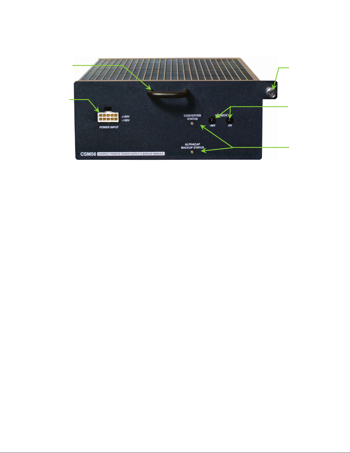
2CONVERTER MODULE FEATURES...............................................................................................................................2
2.1 Microcontroller ............................................................................................................................................. 2
2.2 Indicators ...................................................................................................................................................... 2
2.3 Test Points..................................................................................................................................................... 2
2.4 Lock ............................................................................................................................................................... 2
2.5 Handle ........................................................................................................................................................... 2
2.6 DC Inputs....................................................................................................................................................... 3
2.7 Input Low Voltage Lockout ........................................................................................................................... 3
2.8 Input Current Limit........................................................................................................................................ 3
2.9 DC Output ..................................................................................................................................................... 3
2.10 Output Power................................................................................................................................................ 3
2.11 Over Voltage Protection (OVP) ..................................................................................................................... 3
2.12 Output Current Limit..................................................................................................................................... 3
2.13 Regulation and Paralleling ............................................................................................................................ 3
2.14 Over Temperature Protection ...................................................................................................................... 4
2.15 Ventilation..................................................................................................................................................... 4
2.16 Paralleling Diode ........................................................................................................................................... 4
2.17 Reverse Polarity Operation........................................................................................................................... 4
3INSPECTION .........................................................................................................................................................5
3.1 Packing Materials.......................................................................................................................................... 5
3.2 Check for Damage......................................................................................................................................... 5
4INSTALLATION ......................................................................................................................................................6
4.1 Safety Precautions ........................................................................................................................................ 6
4.2 Tools Required .............................................................................................................................................. 6
4.3 Module Insertion/Removal........................................................................................................................... 6
5WIRING AND CONNECTIONS ....................................................................................................................................8
5.1 Safety Precautions ........................................................................................................................................ 8
5.2 Chassis Ground ............................................................................................................................................. 8
5.3 DC Input ........................................................................................................................................................ 8
5.4 DC Output Shelf Connection......................................................................................................................... 8
6INITIAL STARTUP ...................................................................................................................................................9

iii
6.1 Normal Mode of Operation .......................................................................................................................... 9
6.2 Reverse Polarity Protection .......................................................................................................................... 9
7MAINTENANCE ...................................................................................................................................................10
8ALPHA CONVENTIONS ..........................................................................................................................................11
8.1 Numbering System...................................................................................................................................... 11
8.2 Acronyms and Definitions........................................................................................................................... 11

Alpha Technologies Ltd. 013-034-C0 Rev E
Burnaby, British Columbia. Telephone: 604 436 5900, Fax: 604 436 1233. Page 1 of 11
1Introduction
1.1 Scope of the Manual
This manual explains the features, installation and interconnection of the Alpha Technologies CSM56 down converter
module with integrated backup.
1.2 Product Overview
The CSM56 down converter module uses a high frequency switched mode conversion technique to provide a bulk regulated
–50 to –55 Vdc output from multiple isolated ±190 Vdc inputs. This converter is directly compatible with the Alpha CSM36
48 Vdc to ±190 Vdc up converters that are used in network powering applications.
Network (a.k.a. Express, Simplex, Remote, Centralized) powering is a method of distributing energy over an existing copper
network. Multiple twisted-pair copper wire is used to distribute 100 VA limited power sources at ±190 Vdc. The individual
isolated inputs are terminated at a remote end and converted back to a bulk 48 Vdc supply.
Supercapacitors have been incorporated into the CSM56 to provide at least four (4) seconds of backup for a 350 W, 48 Vdc
load.
The CSM56 module slides and plugs into the Lucent Stinger®1
DSLAM cabinet. The module provides external connections
for inputs and output interfaces.
Figure 1–Perspective view of CSM56 module
1.3 Part Numbers and List Options
This product is available to order under the following part numbers and list options:
Description
CSM56 converter, ±190Vdc to –48V
Part Number/List Option
013-034-20
Basic module *List 0
Charcoal finish with white (contrasting) silkscreen *List 56
* Default option
The above information is valid at the time of publication. Consult factory for up-to-date ordering information.
1Stinger is a registered trademark of Alcatel-Lucent.

Alpha Technologies Ltd. 013-034-C0 Rev E
Burnaby, British Columbia. Telephone: 604 436 5900, Fax: 604 436 1233. Page 2 of 11
2Converter Module Features
Each module contains five (5) isolated DC to DC converters with a control and supervisory circuit.
Figure 2–CSM56 converter module front panel
2.1 Microcontroller
The microcontroller for each converter monitors both the inputs and outputs of the converters, turns the converters on and
off, and generates a fail status indication if a converter fails.
2.2 Indicators
LED indicators on the front panel display the operational status of the module.
2.2.1 Converter Status
This LED indicator illuminates green when all inputs are present and all converters are functioning normally. It illuminates
yellow if the output voltage is within normal range but one or more inputs, or converters, are not functioning.
The LED will not be on or will illuminate red, or alternate red-yellow, if the output is not within the normal range because
of a circuit failure or overload.
2.2.2 AlphaCap Backup Status
This LED indicator illuminates green when the backup capacitors are fully charged and flashing green when they are
charging.
The LED will alternate green-yellow when supplying backup power. It will alternate green-red when over-charging or if the
charging circuit fails.
The LED will not be on, or will illuminate red if the AlphaCap backup system has failed.
2.3 Test Points
There are current limited meter probe test points for each -53Vdc output on the front panel. For accurate (< 2% error) input
voltage measurements, use a voltmeter set to > 20 MWinput resistance.
2.4 Lock
A captive type screw is used to lock the module into place in the Lucent Stinger® DSLAM cabinet.
2.5 Handle
The front mounted grip (handle) is used for easy insertion and removal of the CSM56.
Module lock
Module handle
Input Connector
Output test points
Status indicators

Alpha Technologies Ltd. 013-034-C0 Rev E
Burnaby, British Columbia. Telephone: 604 436 5900, Fax: 604 436 1233. Page 3 of 11
2.6 DC Inputs
A 10-pin female Tyco mini-fit connector is located on the front panel. It is used to connect five (5) ±190 Vdc input power
pairs, which require customer-supplied overvoltage protectors at the host system.
2.7 Input Low Voltage Lockout
A fault detection circuitry electronically protects the converter module from low input voltages. If the input to any
converter falls below the lower DC input limit, the module will shut down and go into a converter fail mode.
2.8 Input Current Limit
A precision input current limit circuit ensures that the CSM56 converter never overloads a CSM36 or compatible converter
(±190 Vdc 100 VA source with 250 mA minimum output).
2.9 DC Output
A 10-pin blind-mate Molex connector is located on the rear panel and plugs into the Lucent Stinger® DSLAM cabinet for the
–48V and +Gnd output terminals.
2.10 Output Power
Each of the isolated converters on the CSM56 module has a maximum output capacity of 75 W for a total capacity of 375 W
per module. The power output is a function of the input voltage into each converter. Proper network engineering and
copper pair sizing is required to accommodate the power demand of the load.
Input Voltage
Figure 3–Power per converter (x5 per CSM56)
2.11 Over Voltage Protection (OVP)
The OVP feature safeguards the module and load from converter over voltages. If an over voltage is detected from a
converter output, the OVP will shutdown the corresponding converter output. The OVP shutdown level is preset at the
factory. Once an over voltage condition is sensed, the microcontroller for that output will attempt to restart the output
repeatedly.
2.12 Output Current Limit
The current limiting function provides a primary response to output overload situations.
2.13 Regulation and Paralleling
Alpha modular converters use “output slope” or “regulation offset” to accomplish load sharing.
Output Power per Converter in Watts
(maximum module power is double)

Alpha Technologies Ltd. 013-034-C0 Rev E
Burnaby, British Columbia. Telephone: 604 436 5900, Fax: 604 436 1233. Page 4 of 11
2.14 Over Temperature Protection
The converter module is protected against excessive ambient temperatures, restricted cooling air flow, or operation at high
altitudes. Under these conditions the converter will shut down and the converter LED will turn red, flash red-yellow, or
switch off.
At 60°C (140°F) or greater the AlphaCaps may switch off. At 70°C (158°F) or greater a converter may switch off. Normal
outputs will return automatically when the ambient temperature drops below the set point.
2.15 Ventilation
The converter is cooled via natural convection and/or forced air-cooling. The air flows from the bottom to the top of the
housing. To maintain proper operation over the full temperature range, allow at least one rack space above and below the
converter shelf. The airflow baffles should be deflecting any heated air away from the input (bottom) of the converter shelf.
The 4-module shelf uses an integrated fan.
2.16 Paralleling Diode
Individual converters are equipped with a paralleling diode to ensure uninterrupted operation of the system in case one
converter fails.
2.17 Reverse Polarity Operation
The converter design allows reverse polarity operation from the connection to a power source on the input. This prevents
damage to the converter circuitry if a reverse connection is made, and allows the output to continue to be powered.
CAUTION: To optimize safety, wire the shelf with the correct polarity on all inputs.

Alpha Technologies Ltd. 013-034-C0 Rev E
Burnaby, British Columbia. Telephone: 604 436 5900, Fax: 604 436 1233. Page 5 of 11
3Inspection
3.1 Packing Materials
All Alpha products are shipped in rugged, double-walled boxes and are suspended via solid inserts to minimize shock that
may occur during transportation. Packaging assemblies and methods are tested to International Safe Transit Association
standards. Power systems are custom packaged in heavy-duty plywood crates.
Products are also packaged with a plastic wrap that contains a corrosive-inhibitor that protects the product from corrosion
for up to two years.
3.1.1 Returns for Service
Save the original shipping container. If the product needs to be returned for service, pack the unit in its original shipping
container. If the original container is unavailable, make sure that the product is packed with at least three inches of shock-
absorbing material to prevent shipping damage.
Alpha Technologies is not responsible for damage caused by the improper packaging of returned products.
3.2 Check for Damage
Before unpacking the product, note any damage to the shipping container. Unpack the product and then inspect the
exterior for damage. Contact the carrier immediately if you see any damage.
Continue the inspection by checking for internal damage. In the unlikely event of internal damage, inform the carrier and
contact Alpha Technologies for advice on the impact of any damage.
Verify that you have all the necessary parts per your order for proper assembly.

Alpha Technologies Ltd. 013-034-C0 Rev E
Burnaby, British Columbia. Telephone: 604 436 5900, Fax: 604 436 1233. Page 6 of 11
4Installation
Only qualified personnel should install and connect the power components within the Alpha power system. For battery
installation, refer to the manufacturer’s manual. Refer to the drawings located at the rear of this manual.
4.1 Safety Precautions
WARNING
Hazardous voltages are present at the input of converter/rectifier systems. The DC output, from the
converters and the AlphaCap system, has a high short circuit current capacity that may cause burns
and electrical arcing.
Before working with any live battery or power system/distribution center, follow these precautions:
•Remove all metallic jewelry; e.g., watches, rings, metal rimmed glasses, necklaces.
•Wear safety glasses with side shields (and prescription lenses if necessary) at all times during installation.
Follow all the applicable local rules and regulations for electrical and battery installations, e.g., CSA, UL, CEC, NEC, OSHA,
and local fire codes.
WARNING
This product is intended to be protected by a surge protector that meets the applicable criteria of GR-
974-CORE or GR-1361-CORE. Failure to utilize this appropriate surge protector could result in
susceptibility to lightning surges or create a potential hazard due to power faults.
CAUTION
Stored energy hazard. Do not open the cover! There are no serviceable parts inside.
4.2 Tools Required
The following tools are required for product installation and startup.
•Philips head screwdriver, #2 with 3/16" tip size.
•High impedance (> 20 MW) digital voltmeter equipped with test leads with 0.080" diameter tips.
4.3 Module Insertion/Removal
To insert a module, place the module on the bottom of the electronic equipment rack, and use the mounting rails to slide
the module into the rear connector inside of the shelf. Apply pressure on the module handle to engage the rear connector
in the shelf receptacle. Do not force a module into position if it does not seat properly.
Tighten the screw on the faceplate to secure the module to the shelf.
To remove a module, loosen the screw on the faceplate. Pull on the module handle and slide the module away from the
rear connector and out of the shelf.

Alpha Technologies Ltd. 013-034-C0 Rev E
Burnaby, British Columbia. Telephone: 604 436 5900, Fax: 604 436 1233. Page 7 of 11
Figure 4–Perspective view of CSM56 module, showing mounting rail
Module locking screw
Mounting rail (2PL)

Alpha Technologies Ltd. 013-034-C0 Rev E
Burnaby, British Columbia. Telephone: 604 436 5900, Fax: 604 436 1233. Page 8 of 11
5Wiring and Connections
5.1 Safety Precautions
WARNING
•For safety reasons, ensure the module retaining fastener (locking screw) is properly tightened to the Lucent
Stinger® DSLAM cabinet. Chassis must be permanently grounded.
•Input voltage must meet UL60950-21 RFT-V requirements. DO NOT CONNECT TO RFT-C CIRCUITS.
•+48 V return (RTN) output shall be earthed in the Lucent Stinger® DSLAM cabinet.
•Telecom cable carrying ±190 V shall be #26 AWG minimum (rated 200 V minimum).
•Primary over voltage protection must be provided on all input pairs.
•Insulation of the outside plant conductors should be rated > 90°C (194°F).
•The effective capacitance of the CSM56 and telecommunication network, at the time of installation, a
system assessment shall be carried out to ensure that the effective capacitance of the total system,
including the capacitance of the CSM56, does not exceed the values specified in Figure 2 of IEC 60950-21.
•For installations in environments exceeding 40°C (104°F), airflow must be provided at a rate of 150 LFM.
•This equipment is to be used in a clean and dry environment.
•Load connections should be made in close proximity to the power shelf.
•Refer to the Installation chapter for additional safety precautions.
•The equipment is to be used in a restricted access location only.
5.2 Chassis Ground
The rear face of the right side securing tab on the painted front panel is plated and masked to ensure a reliable ground
connection when the CSM56 is installed.
5.3 DC Input
Connect the ±190 Vdc input power pairs via the 10-pin Tyco mini-fit connector located on the front panel.
The host system must provide primary input overvoltage protection for each of the telephone wire pairs. The protection
level must correspond to a 5-pin solid-state protector type Corning 303M-11A7T0 or a 5-pin multi-stage protector type
Bourns 2410-31-G-MSP. These modules are designed with short-to-ground systems for all electrical conditions that exceed
their surge capabilities and have a DC breakdown voltage range of 300-400 V and an impulse breakdown voltage of < 700
Volts.
5.4 DC Output Shelf Connection
Insert the CSM56 into the Lucent Stinger® DSLAM cabinet for the –50 V and +Gnd output terminations. The connection is
made via a 10-pin blind-mate Molex connector located on the rear panel.
Figure 5–Rear view of CSM56 module

Alpha Technologies Ltd. 013-034-C0 Rev E
Burnaby, British Columbia. Telephone: 604 436 5900, Fax: 604 436 1233. Page 9 of 11
6Initial Startup
1. Remove the customer-supplied 5-pin protectors from the power-pairs termination block and disconnect the
output –48 V cable.
2. Verify that the system rack is connected to the ground.
3. Mate the input connector with the host connector.
4. Complete the input circuits by plugging in the 5-pin protectors, one by one.
5. Measure the output voltage at the front panel test points.
6. The front panel Converter Status LED will illuminate yellow temporarily, and will illuminate green after the
CSM56 self-test is finished.
7. The AlphaCap Backup Status LED may illuminate red initially, and will then flash green when the AlphaCaps
are charging.
6.1 Normal Mode of Operation
The Converter Status LED will illuminate green during normal operation of the converter system.
The Converter Status LED indicator illuminate yellow if one or more of the inputs are disconnected, or one or more of the
DC-to-DC converters are non-functional, but the output is within its normal range.
The AlphaCap Backup Status LED will flash green during charging and will illuminate green when the supercapacitors are
fully charged.
6.2 Reverse Polarity Protection
The converter design allows reverse polarity operation from the connection to a power source on the input. This prevents
damage to the converter circuitry if a reverse connection is made, and allows the output to continue to be powered.
CAUTION: To optimize safety, wire the shelf with the correct polarity on all inputs.

Alpha Technologies Ltd. 013-034-C0 Rev E
Burnaby, British Columbia. Telephone: 604 436 5900, Fax: 604 436 1233. Page 10 of 11
7Maintenance
This equipment requires regular maintenance. The maintenance must be done by qualified service personnel only.
WARNING: HIGH VOLTAGE AND SHOCK HAZARD. Use extreme care when working inside the shelf
while the system is energized. Do not make contact with live components or parts. Ensure redundant
modules or batteries are used to eliminate the threat of service interruptions while performing
maintenance on the system’s alarms and control settings.
Procedure Date Completed
Clean ventilation openings
Inspect all system connections (re-torque as necessary)
Verify LED operation
Confirm output voltage measured at test points
Table A–Sample maintenance log
CAUTION
Stored energy hazard. Do not open the cover! No serviceable parts inside.

Alpha Technologies Ltd. 013-034-C0 Rev E
Burnaby, British Columbia. Telephone: 604 436 5900, Fax: 604 436 1233. Page 11 of 11
8Alpha Conventions
8.1 Numbering System
Alpha Technologies uses an eight-digit drawing number system, which is broken into three blocks. The first three digits
describe the category of the product; e.g., rectifier or fuse panel. The next three digits indicate the sequence in which the
product number was allocated in a particular category. The last two digits indicate the type of drawing, for example:
“-05” Schematic
“-06” Outline Drawing
“-08” Customer Connections
“-20” Main Assembly
Alpha uses an eight-digit part numbering system for all components and sub assemblies. Each part is covered by its own
unique number. Due to the quantity, categories will not be listed within this manual.
8.2 Acronyms and Definitions
AC Alternating current
AWG American wire gauge
CEC Canadian Electrical Code
CMA Circular mil area
CRPS Compact remote power supply
CSM Converter switched mode
CSA Canadian Standards Association
DC Direct current
DSLAM Digital subscriber line access multiplexer
LED Light emitting diode
NC Normally closed
NEC National Electrical Code (for the USA)
NO Normally open
OSHA Occupational Safety & Health Administration
OVP Over voltage protection
RoHS Restriction of hazardous substances
RU Rack unit (1.75")
SDB Short duration backup
UL Underwriters Laboratories

Specifications for Alpha Technologies’ CSM56 +/–190Vdc Compact Remote
Power Supply and Backup Module
Alpha Technologies Ltd. 013-034-B1 Rev C WC
Burnaby, British Columbia. Telephone: 604 436 5900 Fax: 604 436 1233. Page 1 of 3
System Output
Voltage Range: -50 to -55 Vdc with inputs operational
Current Maximum: 7.5 A @ 50 V (derates linearly with input voltage)
7.8 A @ 45 V
Power: 250 W nominal
375 W maximum (derates linearly with input voltage)
Static Voltage Regulation: 55 V ±1% @ no load
50 V ±1% @ full load (7.5A)
Startup Time: ≤0.3 seconds to rated Vdc @ no load
Startup Overshoot: -60 Vdc in less than 100ms, no OVP trip
Current Limit: 1.6 A x 5
Noise: < 100 mVRMS to 20 MHz (wide band)
< 500 mVp-p to 20 MHz
Meets requirements of GR-1089-CORE,
Section 3.2.2.2 with test method of Section 3.4.5
Acoustic Noise: < 45 dBa at 1m (3 ft)
EMI: Meets requirements of GR-1089-CORE,
Sections 3.2.2.2 and 3.3
Backed Up Output
Voltage: -46Vdc ±3%
Duration Backup: 350 W for > 3.2 seconds @ -40°C (-40°F)
350 W for > 6.4 seconds @ +25°C (+77°F)
30 seconds maximum duration at low load

Specifications for Alpha Technologies’ CSM56 +/–190Vdc Compact Remote Power Supply and Backup Module Continued
Alpha Technologies Ltd. 013-034-B1 Rev C WC
Burnaby, British Columbia. Telephone: 604 436 5900 Fax: 604 436 1233. Page 2 of 3
System Input
Voltage: 200 to 390 Vdc (±100 to ±195 Vdc)
Noise: Compliant to GR-1089-CORE, Section 3.2.2.2 and 3.3
Transient Protection: Compliant to GR-1089-CORE,
Section 4.6.7 for lightning surge susceptibility
Section 4.6.10 for ac power faults
Current: 0.25 A(dc) maximum per input
Efficiency: > 85% @ 100% load
Off State Current: < 30 mA input current per input when module at no load
Power Module Fuse: 10 x 1.25 A, 250 Vac Telecom
Isolation: Inputs isolated other inputs and from outputs and ground;
10 MΩinsulation resistance and ≥1600 Vdc insulation strength
Effective input capacitance of CSM 56 between the connection points for the conductors of the
TELECOMMUNICATION NETWORK (Line-to-Line) Max. 4.6 uF
Effective input capacitance of CSM 56 between the connection point for one conductor of the
TELECOMMUNICATION NETWORK and earth (Line-to-Earth) Max. 8.8 uF
Front Panel Features
Converter Status LED: Green – Outputs OK and inputs OK
Yellow – Outputs OK and one or more inputs NOT OK
Red or Off – Output NOT OK
Test Points: Converter output voltage
AlphaCap Backup Status LED: Green – Charged
Green, flashing – Charging
Red – Failed
Environmental
Temperature: -40 to +40°C (-40 to +104°F) [natural convection]
-40 to +60°C (-40 to +140°F) [with 200 LFM airflow]
Humidity: 0 to 95% non-condensing
Elevation: -500 to 2800 m (-1640 to 9186 ft)
Recommended Connection Wire Sizes
Input: #22 to 26 AWG (0.34 to 0.14 mm²) [5 pairs, 10 conductors]
Output: 8 x #18 to 20 AWG (0.75 to 0.50 mm²)

Specifications for Alpha Technologies’ CSM56 +/–190Vdc Compact Remote Power Supply and Backup Module Continued
Alpha Technologies Ltd. 013-034-B1 Rev C WC
Burnaby, British Columbia. Telephone: 604 436 5900 Fax: 604 436 1233. Page 3 of 3
Mechanical
Module Size: 86.4 mm H x 223.1 mm W x 238.9 mm D, w/ fastener
(3.40" H x 8.78" W x 9.41" D)
86.4 mm H x 223.1 mm W x 264.2 mm D, w/ handle
(3.40" H x 8.78" W x 10.40" D)
Mounting: Slides and fastens into Lucent Stinger® DSLAM cabinet
Module Weight: 2.84 kg (6.26 lb.)
Standards Compliance
This product is certified to meet or exceed the following:
PRODUCT SAFETY
United States: UL 60950-1-2002
UL 60950-21 (RFT-V)
Telcordia GR-1089-CORE, Issue 3 Oct 2002 Section 7
Canada: CSA C22.2 60950-1-03
CSA 60950-21 (RFT-V)
Europe: EN 60950-1
IEC 60950-1
IEC 60950-21 (RFT-V)
EMI/RFI/EMC
United States: FCC Title 47, 2002, Chapter 1, Part 15 Class B
Telcordia GR-1089-CORE, Issue 3 Oct 2002
Canada: ICES-003 Issue 3, Nov 22, 1997
This product is designed to meet or exceed the following:
EMI/RFI/EMC
Europe: EN-ETS 300 386 ERM and EMC
EN 55024, 1998
ENVIRONMENTAL
United States: Telcordia GR-63-CORE, Issue 2, Apr 2002
GR-499 Section 13
Europe: EN 300 019, 1998
OTHER RELEVANT TELCORDIA DOCUMENTS
GR-57-CORE, Issue1: Functional Criteria for Digital Loop Carrier (DLC) Systems
GR-909-CORE, Issue 1: Generic Requirements for Fiber Loop Systems
SR-332, Issue 1: Reliability Prediction for Electronic Equipment
TA-NWT-001500, Issue 1: Generic Requirements for Powering Optical Network Units in FITL Systems
GR-950-CORE: Generic Requirements for Optical Network Unit (ONU) Closures
The above information is valid at the time of publication. Consult factory for up-to-date ordering information.
Specifications are subject to change without notice.
Table of contents
Other Alpha Technologies Power Supply manuals

Alpha Technologies
Alpha Technologies Cordex User manual

Alpha Technologies
Alpha Technologies CFR 7.5K User manual

Alpha Technologies
Alpha Technologies SP0123 User manual

Alpha Technologies
Alpha Technologies GMX-915 User manual

Alpha Technologies
Alpha Technologies CXPS-E3 19 Quick start guide

Alpha Technologies
Alpha Technologies CXPS-E101 User manual

Alpha Technologies
Alpha Technologies CXPS-FR3 Quick start guide

Alpha Technologies
Alpha Technologies APP60S User manual

Alpha Technologies
Alpha Technologies APX Series User manual

Alpha Technologies
Alpha Technologies ALPHA OUTBACK ENERGY LPS36 User manual