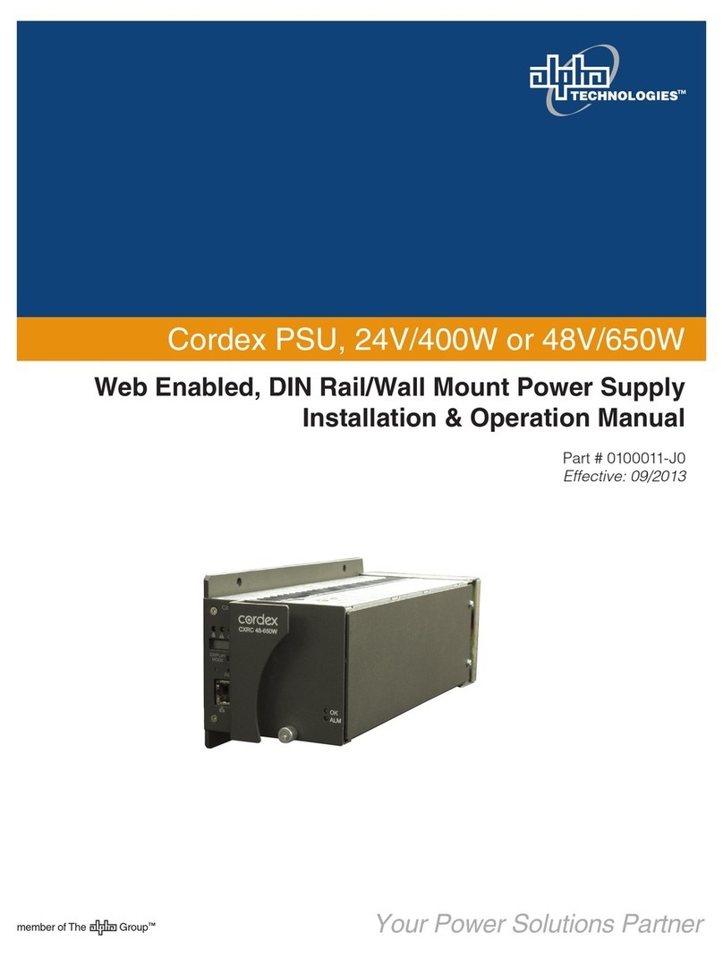
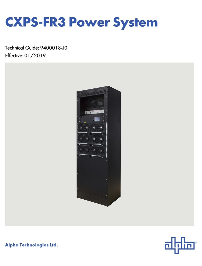
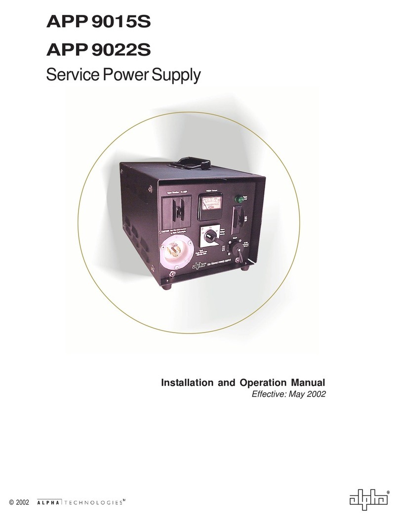
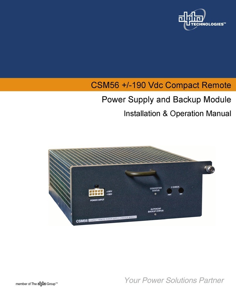
Alpha Technologies CXPS-W Series User manual

Your Power Solutions Partner
CXPS-W Multi-Capacity Power System
member of The Group™
Installation & Operation Manual
Part # 9400010-J0
Effective: 04/2017


CXPS-W Multi-Capacity Power System
Models: 600A – 2000A Power System
For technical support, contact Alpha Technologies:
Canada and USA: 1-888-462-7487
International: +1-604-436-5547
Copyright
Copyright © 2017 Alpha Technologies Ltd. All rights reserved. Alpha is a registered trademark of Alpha Technolo-
gies.
No part of this documentation shall be reproduced, stored in a retrieval system, translated, transcribed, or transmit-
ted in any form or by any means manual, electric, electronic, electromechanical, chemical, optical, or otherwise
without prior explicit written permission from Alpha Technologies.
This document, the software it describes, and the information and know-how they contain constitute the proprietary,
confidential and valuable trade secret information of Alpha Technologies, and may not be used for any unauthorized
purpose, or disclosed to others without the prior written permission of Alpha Technologies.
The material contained in this document is for information only and is subject to change without notice. While
reasonable efforts have been made in the preparation of this document to assure its accuracy, Alpha Technologies
assumes no liability resulting from errors or omissions in this document, or from the use of the information contained
herein. Alpha Technologies reserves the right to make changes in the product design without reservation and with-
out notification to its users.
Alpha shall not be held liable for any damage or injury involving its enclosures, power supplies,
generators, batteries, or other hardware if used or operated in any manner or subject to any
condition inconsistent with its intended purpose, or if installed or operated in an unapproved
manner, or improperly maintained.
Photographs contained in this manual are for illustrative purposes only. These photographs
may not match your installation.
NOTE:
Operator is cautioned to review the drawings and illustrations contained in this manual before
proceeding. If there are questions regarding the safe operation of this powering system, contact
Alpha Technologies or your nearest Alpha representative.
NOTE:
NOTE:


3
9400010-J0 Rev. D
Table of Contents
1. Safety....................................................................................................................................6
1.1 Safety Symbols .......................................................................................................................... 6
1.2 General Safety ........................................................................................................................... 6
1.3 Mechanical Safety...................................................................................................................... 6
1.4 Electrical Safety ......................................................................................................................... 7
1.5 Battery Safety ............................................................................................................................ 7
2. Introduction ...........................................................................................................................8
2.1 Scope of the Manual .................................................................................................................. 8
2.2 Product Overview....................................................................................................................... 8
3. Specications........................................................................................................................9
4. Features..............................................................................................................................11
4.1 System Overview ......................................................................................................................11
4.2 Cordex HP Controller (CXC HP).............................................................................................. 20
4.3 External Peripherals................................................................................................................. 21
4.4 Cordex HP 4.0kW Rectiers .................................................................................................... 23
4.5 2.4kW Rectier Shelf ............................................................................................................... 25
4.6 2.0Kw 48V to 24V Converter Shelf .......................................................................................... 27
4.7 Integrated Battery Trays........................................................................................................... 28
4.8 Remote Return Bar Kit............................................................................................................. 29
5. Inspection............................................................................................................................31
5.1 Packing Materials..................................................................................................................... 31
5.2 Check for Damage ................................................................................................................... 31
5.3 General Receipt of Shipment................................................................................................... 31
6. Installation...........................................................................................................................32
6.1 Safety Precautions................................................................................................................... 32
6.2 Tools Required ......................................................................................................................... 32
6.3 Installation of External Batteries .............................................................................................. 32
6.4 Power System Assembly and Mounting................................................................................... 35

9400010-J0 Rev. D
4
7. Wiring..................................................................................................................................36
7.1 Installation Notes ..................................................................................................................... 36
7.2 Grounding ................................................................................................................................ 37
7.3 AC Supply for the Rectiers ..................................................................................................... 38
7.4 AC Wiring 2.4kW Rectier Shelf .............................................................................................. 40
7.5 DC Wiring................................................................................................................................. 42
7.6 Dual Voltage Conversion ......................................................................................................... 44
7.7 High Capacity Breaker Alarm and Shunt Wiring ...................................................................... 45
7.8 Signal Wiring............................................................................................................................ 46
8. System Startup ...................................................................................................................48
9. Maintenance .......................................................................................................................50
10. Acronyms and Denitions .................................................................................................51
11. Warranty and Service Information.....................................................................................52
11.1 Technical Support................................................................................................................... 52
11.2 Warranty Statement ............................................................................................................... 52
11.3 Limited Hardware Warranty.................................................................................................... 52
11.4 Battery Warranty .................................................................................................................... 52
11.5 Warranty Claims..................................................................................................................... 52
11.6 Service Centers...................................................................................................................... 52
12. Certication.......................................................................................................................53

5
9400010-J0 Rev. D
List of Figures
Figure 1 — Front angle view of the CXPS-W system ....................................................................... 8
Figure 2 — LVD Override and Manual Battery Disconnect............................................................. 12
Figure 3 — 12 Position Internal Return (top of 4T and 2T)............................................................. 17
Figure 4 — 12 Position Internal Return (bottom of 3T and 4T)....................................................... 17
Figure 5 — Cable Lacing Bar Kit .................................................................................................... 19
Figure 6 — Cordex CXC HP Controller (left and right side views).................................................. 20
Figure 7 — LCD Color Touchscreen Display .................................................................................. 21
Figure 8 — L-ADIO I/O Peripheral .................................................................................................. 21
Figure 9 — 6I-ADIO Power Module ................................................................................................ 22
Figure 10 — Cordex HP 4.0kW Rectier ........................................................................................ 23
Figure 11 — Rectier Front Panel LEDs ......................................................................................... 25
Figure 12 — Rectier Front Panel LEDs......................................................................................... 27
Figure 13 — Iinterbay Busing (2000A shown here) ........................................................................ 30
Figure 14 — Rack Mounting Details (top view), Welded Rack ....................................................... 35
Figure 15 — Rack Mounting Details (top view), Bolted Rack ......................................................... 35
Figure 16 — Connecting the Frame Ground................................................................................... 38
Figure 17 — Shelf AC Connection (3-phase, 3-wire shown with rear cover removed)................... 38
Figure 18 — CAN Bus Termination................................................................................................. 39
Figure 19 — CAN OUT Connection................................................................................................ 39
Figure 20 — AC Input and Ground for 23" Shelf............................................................................. 40
Figure 21 — Terminator .................................................................................................................. 41
Figure 23 — Battery Temperature Probes ...................................................................................... 43
Figure 24 — Battery Temperature Probes—battery bay................................................................. 43
Figure 22 — Distribution and I/O Interface Board........................................................................... 43
Figure 25 — Dual Voltage Tier, Factory Congured ....................................................................... 44
Figure 26 — Dual Voltage Tier Converted ...................................................................................... 44
Figure 27 — High Capacity Breaker Alarm and Shunt Wiring ........................................................ 45
Figure 29 — Alarm Relay Pinouts................................................................................................... 46
Figure 28 — Relay Connections, Not Energized State................................................................... 46
Figure 30 — Digital Input Connection Method ................................................................................ 47
9400010-J0 Rev. D
6
1. Safety
SAVE THESE INSTRUCTIONS: This manual contains important safety instructions that must
be followed during the installation, servicing, and maintenance of the product. Keep it in a safe place. Review the
drawings and illustrations contained in this manual before proceeding. If there are any questions regarding the safe
installation or operation of this product, contact Alpha Technologies or the nearest Alpha representative. Save this
document for future reference.
1.1 Safety Symbols
To reduce the risk of injury or death, and to ensure the continued safe operation of this product, the following sym-
bols have been placed throughout this manual. Where these symbols appear, use extra care and attention.
The use of ATTENTION indicates specic regulatory/code requirements that may affect the
placement of equipment and /or installation procedures.
WARNING!
WARNING presents safety information to PREVENT INJURY OR DEATH to personnel. Warnings
are indicated by a shock hazard icon, the word WARNING, and a rule beneath which the infor-
mation appears.
CAUTION!
CAUTION indicates safety information intended to PREVENT DAMAGE to material or equipment.
Cautions are designated with a yellow warning triangle, the word CAUTION, and a rule beneath
which the information appears.
NOTE:
A NOTE provides additional information to help complete a specic task or procedure. Notes
are designated with a check mark, the word NOTE, and a rule beneath which the information ap-
pears
HOT!
HOT symbol indicates safety information to PREVENT BURNS to the technician or user.
1.2 General Safety
WARNING!
This system is designed to be installed in a restricted access location that is inaccessible to the
general public.
1.3 Mechanical Safety
• Keep hands and tools clear of fans. Fans are thermostatically controlled and switch on automatically.
• Power supplies can reach extreme temperatures under load.
• Use caution around sheet metal components and sharp edges.

7
9400010-J0 Rev. D
1.4 Electrical Safety
WARNING!
WARNING!
WARNING!
• Before working with any live battery or power system, follow these precautions:
a. Remove all metallic jewelry, such as watches, rings, metal rimmed glasses, or necklaces.
b. Wear safety glasses with side shields at all times during the installation.
c. Use OSHA approved insulated hand tools.
Lethal voltages are present within the power system. Always assume that an electrical connec-
tion or conductor is energized. Check the circuit with a voltmeter with respect to the grounded
portion of the enclosure (both AC and DC) before performing any installation or removal proce-
dure.
• Do not work alone under hazardous conditions.
• A licensed electrician is required to install permanently wired equipment. Input voltages can range up to 277 Vac.
Ensure the utility power is disconnected and locked out before performing any installation or removal procedure.
• Ensure that no liquids or wet clothes come into contact with internal components.
• Hazardous electrically live parts inside this unit are energized from the batteries even when the AC input power is
disconnected.
Follow battery manufacturer’s safety recommendations when working around battery systems.
Do not smoke or introduce an open ame when batteries (especially vented batteries) are charg-
ing. When charging, batteries vent hydrogen gas, which can explode.
• Batteries are hazardous to the environment and should be disposed at a recycling facility. Consult the battery
manufacturer for recommended local authorized recyclers.
Hazardous voltages are present at the input of power systems. The DC output from rectiers
and batteries, though not dangerous in voltage, has a high short-circuit current capacity that
may cause severe burns and electrical arcing.
WARNING!
HIGH LEAK CURRENT. Earth connection is essential before connecting the supply.
CAUTION! and HOT!
Internal DC breakers can be hot surfaces. Use a bullet socket removal tool for removal of circuit
breakers.
1.5 Battery Safety
• Servicing and connection of batteries must be performed by, or under the direct supervision of, personnel knowl-
edgeable of batteries and the required safety precautions.
• Always wear eye protection, rubber gloves, and a protective vest when working near batteries. Remove all metal-
lic objects from your hands and neck.
• Use OSHA approved insulated hand tools. Do not rest tools on top of batteries.
• Batteries contain or emit chemicals known to cause cancer and birth defects or other reproductive harm. Battery
post terminals and related accessories contain lead and lead compounds. Wash your hands after handling bat-
teries.

9400010-J0 Rev. D
8
2. Introduction
2.1 Scope of the Manual
This manual covers the features, options, installation and startup of Alpha Technologies CXPS-W power system. Im-
ages contained in this document are for illustrative purposes only and may not exactly match your installation.
In addition to this manual, the following documents may be included in the documentation package that ships with
the CXPS-W:
• Cordex HP Controller Software manual: 0350058-J0
• Cordex HP Controller and I/O Peripherals Hardware manual: 0180036-J0
• Cordex HP 48-4.0kW Rectifier and Shelf manual: 9400000-J0
• Cordex DC/ DC Converter CXDF 48-24/2kW manual: 012-527-B2
• Cordex 48-2.4 kW Rectifier and Shelf manual: 0300040-J0
2.2 Product Overview
The CXPS-W is a compact multi capacity power system designed for cell site, small CO and cable head end ap-
plications. The systems can be factory equipped with DC to DC converters and a secondary distribution bus to
distribute power at +24Vdc to secondary loads. The distribution options are extremely flexible; providing TPL fuse
distribution, high capacity breaker distribution, TPS/TLS fuse distribution, and plug in breakers. Shunts are available
for both tier and branch current monitoring.
The system may also be configured with either low voltage load disconnect (LVLD) or low voltage battery disconnect
(LVBD) functionality.
The system utilizes standard Cordex Power System (CXPS) components and is a
perfect solution for space constrained applications due to the compact, front access
design.
Systems are equipped with the CXC-HP system controller for single point control,
advanced battery diagnostics, data logging plus local and remote monitoring, includ-
ing SNMP alarming.
The CXPS-W system is suitable for installation in all following locations:
• Network Telecommunication Facilities
• Locations where the NEC applies
Wireless Applications
• Dual voltage power plant for wireless applications using 48V-24V converters
• Field convertible tiers provide flexibility in distribution for dual voltage applica-
tions
• High density of 2.4kW rectifiers, provide capability to add multiple battery
trays below the power system
Wireline Applications
• System can be installed close to the equipment at the end of a line up, using
high capacity circuits (TPL fuses/GJ style breakers) to feed remote distribution
panels (RDPs) mounted in equipment bays.
• Can be equipped with AM style breakers or TPS/TLS fuses that directly feed
the network equipment in a distributed architecture (DA)
• Larger rectifiers (4.0kW) provide the flexibility to configure economical higher
ampacity systems
Figure 1 — Front angle view of the CXPS-W system

9
9400010-J0 Rev. D
3. Specifications
Table A — Specications CXPS-W
Electrical
Primary Output Voltage: -48V
Secondary Output Voltage:
(optional) +24V
4.0kW Rectier Shelf AC Input:
6x 30A, Single Phase, 208 to 277Vac
2x 50A, 3 Phase, 208Vac (w/o neutral)
2x 30A, 3 Phase, 277/480Vac (w/ neutral)
2.4kW Rectier Shelf AC Input: 2x 40A & 1x 20A Single Phase, 208 to 277Vac
Distribution
System Ampacity Ratings
(Continuous):
1 Tier System Bus Capacity: 600A
2 Tier System Bus Capacity: 1200A
3 Tier System Bus Capacity: 1200A (or) 1800A
4 Tier System Bus Capacity: 1200A (or) 2000A
Fuses
GMT: 30A, 10 positions (15A max. fuse)
TPL(HC*): Up to 8 positions in a 4T Distribution, (800A max. fuse)
TPL (LC*): Up to 16 positions in a 4T Distribution, (400A max. fuse)
TLS/TPS Plug-in Bullet: Up to 96 positions
Breakers
Plug-in Bullet: Up to 96 positions in a 4T Distribution System
High Capacity Bolt-in: Up to 24 positions in a 4T Distribution System
Output Termination
GMT: 0.34 to 2.5mm2 (14 to 22AWG)
TPL(HC*): 2x ⅜" studs on 1" centers (Up to 2x 750 MCM Cables)
TPL (LC*): 1x ⅜" studs on 1" centers (Up to 1x 750 MCM Cables)
High Capacity Bolt-in: 1x ⅜" studs on 1" centers (Up to 1x 750 MCM Cables)
TLS/TPS/Plug-In Bullet: 1 pole are¼" studs on ⅝" centers, 2 pole and 3 pole are ⅜" diameter on 1"
centers
Internal Ground Bar ¼" studs on ⅝" centers
External Ground Bar: Optional
Battery: 5x ⅜" hole on 1" centers per polarity
System Level Alarms and Controls
Indicators:
LCD with touch screen:
System OK (green LED)
System minor alarm (yellow LED)
System major alarm (red LED)
Alarm Connections: >0.34 to 2.5mm2(14 to 22AWG)
Mechanical
Mounting:
Standard center mount 23" relay rack
mm: 2133H x 660W x 560D
inches: 84H x 26W x 22D

9400010-J0 Rev. D
10
Weight:
System: 227kg (500lbs) approx
4.0kW Rectier: 8.5kg (19lbs) per module
2.4kW Rectier: 1.76kg (3.9lbs) per module
Environmental
Operating Temperature: 0 to 40°C (32 to 104°F)
Storage Temperature:
Humidity: 0 to 95% RH non-condensing
Elevation: 500 to 2800m (-1640 to 9186ft)
Compliance
CSA: CSA C22.2 No. 60950-1
UL 60950-1
The above information is valid at the time of publication. Consult factory for up-to-date ordering information.
Specications are subject to change without notice.

11
9400010-J0 Rev. D
4. Features
4.1 System Overview
4.1.1 Seismic Racks
The CXPS-W system can be installed in a variety of Alpha provided, 23” seismic racks. These racks have been Z4
rated and NEBS L3 certified. The racks vary in their Z4 seismic capabilities from 500. lb to 2500 .lb and in their
heights from a 3.5’ to 9’ racks (standard 7’ racks are available as well). For more ordering information, refer to the
CXPS-W Ordering Guide on the Alpha website.
Certain list options on the one tier (1T), and the two tier (2T)
systems can be purchased with system mounting brackets
so that the systems can be installed into existing customer
provided racks.
• 7RU = 1 Tier + 2x 2.4kW Rectifier Shelves
• 9RU = 1 Tier + 1x 4.0kW Rectifier Shelf
• 11RU = 2 Tier + 2x 2.4kW Rectifier Shelves
• 13 RU= 2 Tier + 1x 4.0kW Rectifier Shelf (or) 2 Tier + 4x
2.4kW Rectifier Shelves
• 17RU = 2 Tier + 2x 4.0kW Rectifier Shelves
4.1. 2 Distribution Cabinets
4.1.2 .1 One Tier
• Accepts a maximum of one distribution tier
• Rated for a max of 600A
• 5RU in height
• Five battery landing positions (ten cables back to back)
(return bar has one extra position for the site ground)
• Max lug tongue width: 1.63"
4.1.2.2 Two Tier
• Accepts a maximum of two distribution tiers
• Rated for a max of 1200A
• Option for a 1200A LVBD
• 9RU in height
• Five battery landing positions (ten cables back to back)
(return bar has one extra position for the site ground)
• Max lug tongue width: 1.63"

9400010-J0 Rev. D
12
4.1.2 .3 Three Tier
• Accepts a maximum of three distribution tiers
• Rated for a max of 1200A or 1800A
• Option for a 1200A or 2000A LVBD
• 14RU in height
• Five battery landing positions (ten cables back to back)
(return bar has one extra position for the site ground)
• Max lug tongue width: 1.63"
4.1.2 .4 Four Tier
• Accepts a max of four distribution tiers
• Rated for a max of 1200A or 2000A
• Option for a 1200A or 2000A LVBD
• 20 RU in height
• Five battery landing positions (ten cables back to back)
(return bar has one extra position for the site ground)
• Max lug tongue width: 1.63"
4.1.3 Low Voltage Battery Disconnect (LVBD) Option
The Cordex CXC HP controller monitors battery voltage. If AC power is lost, the batteries continue to provide DC
power to the load and the converters (if present). When the battery voltage reaches a predetermined (adjustable)
level, the controller will disconnect the batteries to protect them from full discharge.
The LVBD option includes a manual disconnect switch and terminal block for field wiring an external switch to dis-
connect the batteries manually from either within the distribution unit or remotely. The LVD override switch provides
users with the ability to inhibit or override LVD contactor operations as a safeguard during controller maintenance. A
green LED lights up when the LVD is in normal operation mode (auto) and a yellow LED signals when the switch has
been placed in the override position.
Figure 2 — LVD Override and Manual Battery Disconnect
Manual battery disconnect
LVD Override
EPO

13
9400010-J0 Rev. D
4.1.4 24 Position Bullet Tier Features
• Occupies 1 tier position
• Can be installed in any location of the ‘W’ distribution cabinet
• 600A tier rating (Monitored by 800A shunt)
• Each tier accepts 1P (125A), 2P (200A), 3P (300A)
• 1P breaker/fuse (1/4” stud on 5/8” center)
• 2P & 3P breaker (3/8” stud on 1” center), via adapters
• Option for tier with internal return
• Max lug tongue width: 0.60" (1.06" with adapters)
4.1.5 24 Position Staged Bullet Tier Features
Tier can be configured as 12 positions on primary bus and 12 positions on secondary bus (or) 16 positions on pri-
mary bus and 8 positions on secondary bus (or) 20 positions on primary bus and 4 positions on secondary bus (or)
all 24 positions on primary bus.
• Occupies 1 tier position
• Can be installed in any location in any of the ‘W’ distribution cabinet
• 600A tier rating (Monitored by 800A shunt)
• The secondary to primary (or vice vers) can be converted in the field if required
• Each tier accepts 1P (125A), 2P (200A), 3P (300A)
• 1P breaker/fuse (1/4” stud on 5/8” center)
• 2P & 3P breaker (3/8” stud on 1” center), via adapters
• Option for tier with internal return
• Max lug tongue width: 0.60" (1.06" with adapters)
Any 1P Over Current Protection device, rated at 125A, requires an empty space on either side.
NOTE:
Any 1P Over Current Protection device rated at 125A requires an empty space on either side.
NOTE:

9400010-J0 Rev. D
14
4.1.6 20 Position LVLD Bullet Tier Features
• Occupies 1 tier position
• Can be installed in any location in any of the ‘W’ distribution cabinet
• 600A tier rating (Monitored by 800A shunt)
• Load shedding via 600A contactor
• Each tier accepts 1P (125A), 2P (200A), 3P (300A)
• 1P breaker/fuse (1/4” stud on 5/8” center)
• 2P & 3P breaker (3/8” stud on 1” center), via adapters
• Option for tier with internal return
• Max lug tongue width: 0.60" (1.06" with adapters)
4.1.7 Low Voltage Load Disconnects (LVLD)
The Low Voltage Load Disconnect (LVLD) option controls a high capacity contactor that disconnects the load dur-
ing predetermined low voltage conditions. Similarly the Low Voltage Battery Disconnect (LVBD) option disconnects
battery at a preset disconnect voltage. The system loads and batteries are automatically reconnected once AC is
restored and battery voltage has risen above a preset value.
4.1.8 2 Position TPL Tier Features
• Occupies 1 tier position
• Can be installed in any location in any of the ‘W’ distribution cabinet
• 600A tier rating (Monitored by 800A shunt)
• Each position accepts max 800A TPL fuse
• Current on each TPL is monitored via a 800A shunt
• 3x landings per fuse (3/8” nuts on 1” center)
• Option for tier with internal return
• Max lug tongue width: 1.63"
Any 1P Over Current Protection device rated at 125A requires an empty space on either side.
NOTE:

15
9400010-J0 Rev. D
4.1.9 4 Position TPL Tier Features
• Occupies 1 tier position
• Can be installed in any location in any of the ‘W’ distribution cabinet
• 600A tier rating (Monitored by 800A shunt)
• Each position accepts max 400A TPL fuse
• Current on each TPL is monitored via a 400A shunt
• 1x landings per fuse (3/8” nuts on 1” center)
• Max lug tongue width: 1.63"
2 Position TPL Tier Theory of Operation
800A TPL 800A TPL
600A
300A
(A Side)
300A
(B Side)
TPL 1 TPL 2
LOAD
If TPL 1 (or) TPL 2 operate and open, then the other TPL will carry the entire load current and not exceed the 80%
rating of the fuse and the 600A rating of the tier.
4 Position TPL Tier Theory of Operation
400A TPL 400A TPL
300A
150A
(A Side)
150A
(B Side)
400A TPL 400A TPL
300A
150A
(C Side)
150A
(D Side)
TPL3 TPL 4
LOAD 2
TPL 1 TPL 2
LOAD 1
If TPL 1 (or) TPL 2 / TPL 3 (or) TPL 4 operate and open, then the other TPL will carry the entire load current and not
exceed the 80% rating of the fuse and the 600A rating of the tier.

9400010-J0 Rev. D
16
4.1.10 4 Position TPL Tier Features
• Occupies 1 tier position
• Can be installed in only the top tier in any of the ‘W’ distribution cabinet
• 1200A tier rating (Monitored by 1500A shunt)
• Each position accepts max 800A TPL fuse
• Current on each TPL is monitored via a 800A shunt
• 2x landings per fuse (3/8” nuts on 1” center)
• Max lug tongue width: 1.75"
4.1.11 4 Position High Capacity Breaker Tier Features
• Occupies 1 tier position
• Can be installed in any location in any of the ‘W’ distribution cabinet
• 600A tier rating (Monitored by 800A shunt)
• Can accept 1P-4P(800A Max) GJ style breaker
• Breakers could be ordered with built in shunts for individual load current monitoring
• 1x landings per position (3/8” nuts on 1” center)
• Option for tier with internal return
• Max lug tongue width: 1.63"
Limitation: Cannot land more than two 750 MCM cables on this tier option with an internal return.

17
9400010-J0 Rev. D
4.1.12 12 Position High Capacity Breaker Tier Features
• Occupies 2 tier positions
• Can be installed only in specific location within the ‘W’ distribution cabinet
xTiers 1 and 2, in a 2T distribution cabinet
xTiers 1 and 2, in a 3T distribution cabinet
xTiers 1 and 2 and tiers 3 and 4, in a 4T distribution cabinet
• 1800A tier rating (Monitored by 2500A shunt)
• Can accept 1P-4P (800A Max) GJ style breaker
• Breakers could be ordered with built in shunts for individual load current monitoring
• 1x landings per position (3/8” nuts on 1” center)
• Option for tier with internal return
• Max lug tongue width: 1 Pole: 1.06”, 2 Pole: 1.06”, 3 Pole: 1.63”, 4 Pole: 1.63”
4.1.13 12 Position Internal Return Bar
• Can only be installed in specific locations of the 2T, 3T and 4T ‘W’ distribution cabinets
xMaximum of 1 return bar in a 2T distribution cabinet
xMaximum of 1 return bar in a 3T distribution cabinet
xMaximum of 2 return bars in a 4T distribution cabinet
• 1800A tier rating
• 12x landings (3/8” nuts on 1” center)
Figure 3 — 12 Position Internal Return (top of 4T and 2T)
Figure 4 — 12 Position Internal Return (bottom of 3T and 4T)

9400010-J0 Rev. D
18
4.1.15 Top Cover for distribution cabinet
• The top cover is a flexible shield that is made of insulated material that can be ordered and installed on top
of the distribution cabinet.
• The covers helps prevent metallic objects from falling into the distribution cabinet,
• Individual cutouts can be made on the cover to enable cable routing access
4.1.14 10 Position GMT Fuse block
• Mounted on the side of the distribution cabinet
• 30A max rating
• Can accept 15A GMT fuses
Only install a 15A fuse if the adjacent positions are empty. Otherwise install a 10A fuse maxi-
mum per position.
NOTE:
Table of contents
Other Alpha Technologies Power Supply manuals

Alpha Technologies
Alpha Technologies GMX-915 User manual

Alpha Technologies
Alpha Technologies CXPS-E101 User manual

Alpha Technologies
Alpha Technologies APX Series User manual

Alpha Technologies
Alpha Technologies CXPS-FR3 Quick start guide

Alpha Technologies
Alpha Technologies ALPHA OUTBACK ENERGY LPS36 User manual

Alpha Technologies
Alpha Technologies CFR 7.5K User manual

Alpha Technologies
Alpha Technologies SP0123 User manual

Alpha Technologies
Alpha Technologies MPS48-7M User manual

Alpha Technologies
Alpha Technologies CSM56 User manual

Alpha Technologies
Alpha Technologies Cordex User manual