ALSATOM SU MPC series –SERVICE MANUAL
-alsa apparecchi medicali s.r.l. -
2
PREFACE
Purpose of this manual is to supply instructions to test features and adjust the unit for a properly trained
technical staff, allowing to solve most common failures.
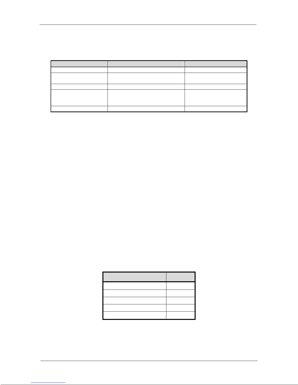
EQUIPMENT NEEDED
DESCRIPTION FEATURES EXAMPLE
Dual trace oscilloscope BandWidth: > 40 MHz Tektronix mod. TDS210
True RMS digital
multimeter Precision Class: 2% Tektronix mod. DMM912
Current probe BandWidth: 200 Hz÷50 MHz Tektronix mod. P6021
H.F. power and leakage
current tester for
electrosurgery Precision Class: 5% Fluke 454A
Supplementary display (*) -
(*) Supplementary display is needed to test SU 100 MPC and SU 50 MPC, since they can’t show setting
output power.
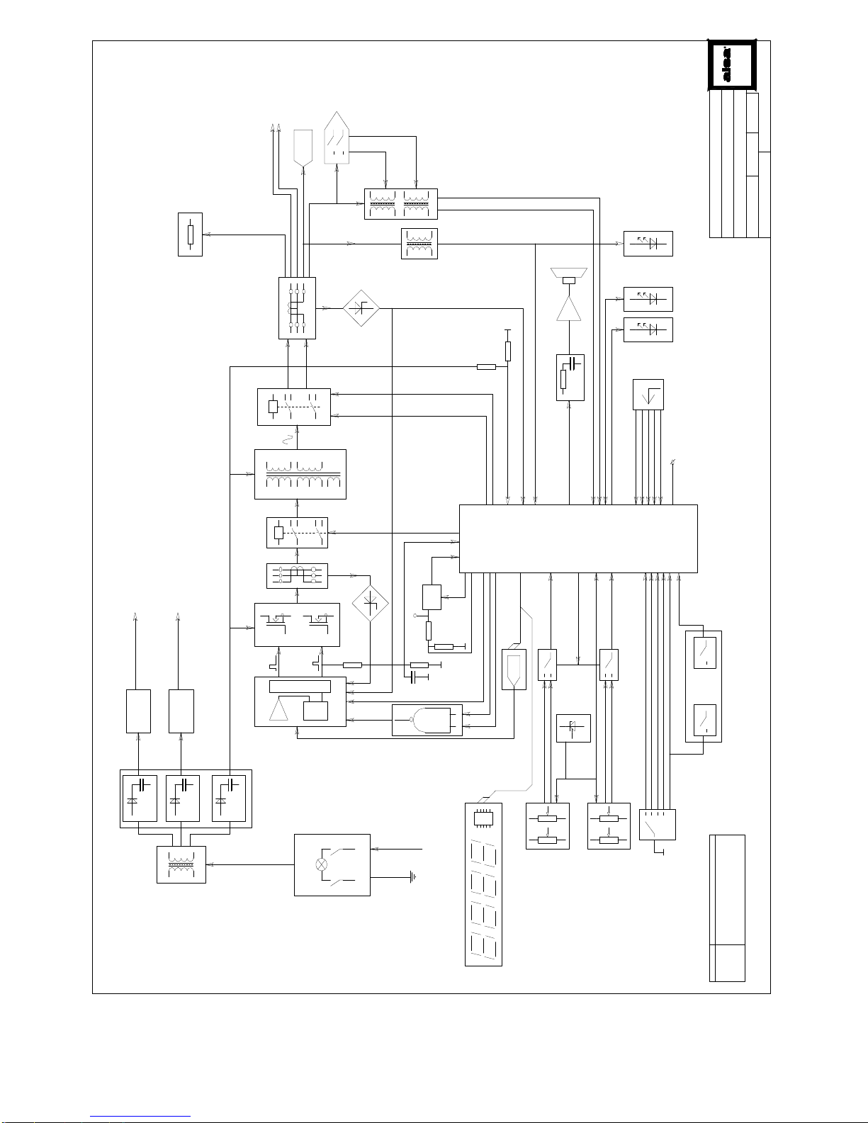
INTRODUCTION
ALSATOM SU MPC series electrosurgical units are made up of the following sections:
•Microcontroller section;
•HF output power section;
•Power display section (only for SU 140, 140/D, SU 140/BD);
•Handle control section (only for SU 140 e 140/D).
Microcontroller section performs main system functions: according to signals coming from HF output power
section, setting commands and monitoring circuits, it enables HF output power delivery, blocking it as soon
as control parameters are out of normal safety conditions. Driving signals for HF output power section are
delivered in this section as well.
HF output power section is composed by a mosfet push-pull configuration: throughout the HF output
transformer, it supplies HF power available in output connections. Some relays drive the waveform either to
monopolar or bipolar output, blocking HF power in not used output receptacle.
Since HF output power is higher than 50 Watts in all models, neutral plate alarm is supplied: this blocks HF
power delivery as soon as a neutral electrode failure occurs. Failed condition is displayed with a red light and
error code PPP (in 140/D and 140 only) on front panel together with an acoustic signal
SU 140/D and SU 140 models are provided with two 3-digit seven-segment displays to allow user to set HF
power in both cut and coagulation modes. Furthermore user can usespencils with pushbuttons to activate
these models, due to a circuit to allow activation for theseaccessories.
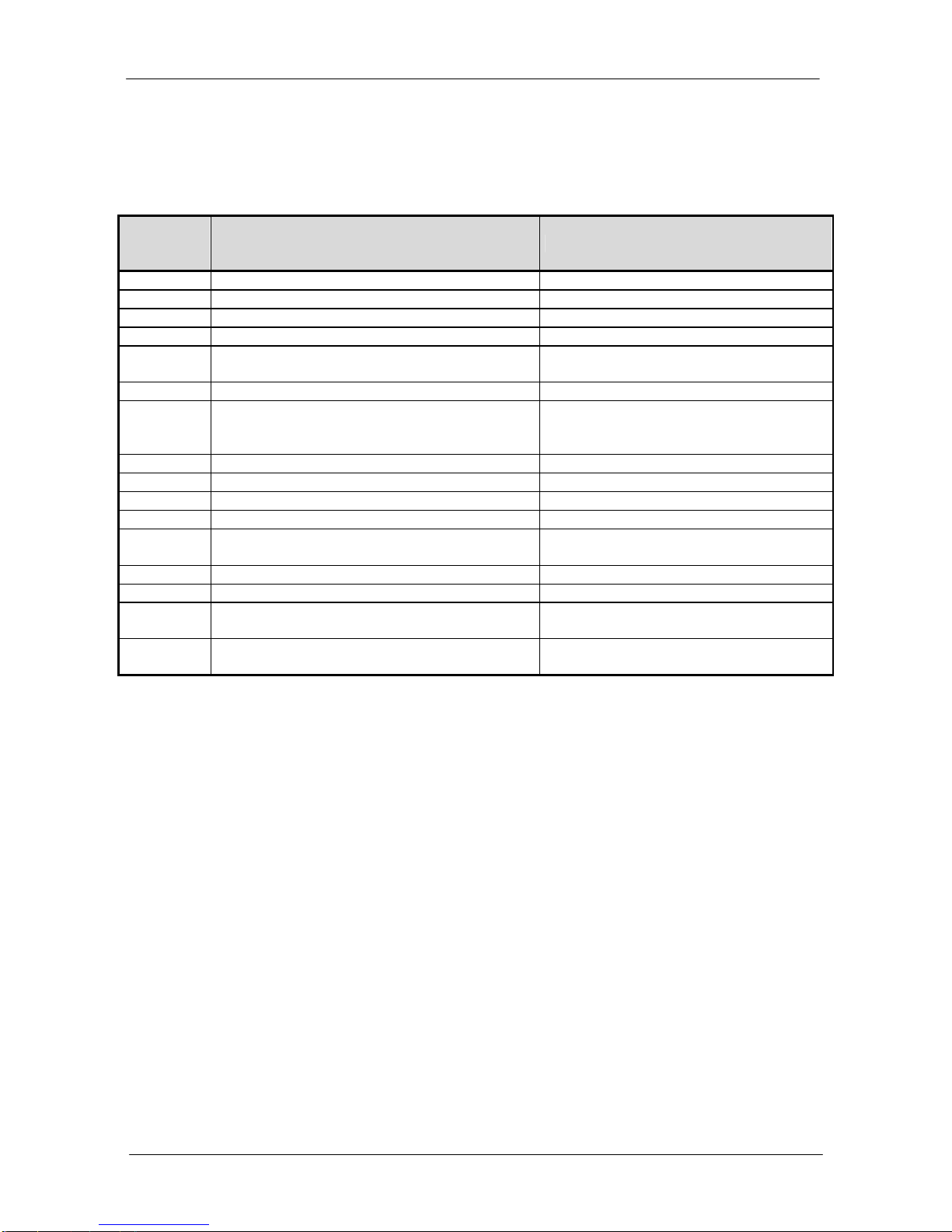
Switching the unit ON, SU MPC performs a selftest phase to check if all parameters are in safety range.
During the selftest, displays show 8.8.8. 8.8.8.,cut and coagulation activation lightsis on. Next, CUT display
shows “L“with software release for few seconds. At the same time COAGULATION display shows a digit
from 1 to 5: this means what model is (refers to the following table).
Coagulation display Code Model
1SU 140/D
2SU 140
3SU 100
4SU 50
5SU 140/BD